

Page 1
PowerScan™
Handheld Laser Scanner
Programming Guide
Page 2

PSC Scanning, Inc.
959 Terry Street
Eugene, Oregon 97402
Telephone: (541) 683-5700
Telefax: (541) 345-7140
All rights reserved. No part of the contents of this documentation or the procedures described
therein may be reproduced or transmitted in any form or by any means without prior written
permission of PSC Inc. Owners of PSC Inc.’s products are hereby granted non-exclusive,
revocable license to reproduce and transmit this documentation for the purchaser’s own internal business purposes. Purchaser shall not remove or alter any proprietary notices, including
copyright notices, contained on this documentation and shall ensure that all notices appear on
any reproductions of the documentation.
Should future revisions of this manual be published, you can acquire printed versions by contacting PSC Customer Administration. Electronic versions will either be downloadable from the
PSC web site (www.pscnet.com) or provided on appropriate media. If you visit our web site
and would like to make comments or suggestions about this or other PSC publications, please
let us know via the “Contact PSC” page.
Disclaimer
Reasonable measures have been taken to ensure that the information included in this
manual is complete and accurate. However, PSC reserves the right to change any
specification at any time without prior notice.
PSC and the PSC logo are registered trademarks of PSC Inc. All other trademarks and trade
names referred to herein are property of their respective owners.
PowerScan™ is a trademark of PSC, Inc.
is a registered trademark of International Business Machines Corporation, NCR is a regis-
IBM
tered trademark of NCR Corporation, and Wincor Nixdorf is registered trademark of Wincor
Nixdorf GmbH & Co. KG. Their inclusion in this manual is for customer information only, and
constitutes neither an endorsement nor a recommendation for these companies’ products or
services.
Page 3

Table of Contents
Introduction..................................................................................................................................1
Understanding the Basics............................................................................................................1
Integrating the Scanner With Your Host System.........................................................................2
Changing Interfaces ........................ ..... ........................................... .... ..........................2
Hardware ................................................................................................................2
Software ..................................................................................................................4
Customizing Your Scanner’s Operation ............................ .... ..... ...................................5
Programming Overview...................................... ..... ..... .......................................... ..... ................6
What Is Programming Mode? ........................................................................................6
Programming Session .................................................. .......................................... ..... ..7
Programming Sequence ........................................ ..... .......................................... ..9
LED and Beeper Indicators........................................................................................................11
LED Indicators ......................................................................................................11
The Beeper ...........................................................................................................11
If You Make a Mistake...............................................................................................................12
Return to Factory Settings ...........................................................................................12
Where To Go From Here...........................................................................................................13
Interface Selection............. ..... ..... .... ........................................... ..... ..........................................14
Wand Emulation Interface ...........................................................................................14
Wand Emulation Settings ............................................................................................15
Wand Emulation Pre/Post-Noise Settings ............................................................18
RS-232 Interface/WN-RS-232 (SNI) Interface .............................................................20
RS-232 Communication Parameters ...........................................................................20
Baud Rate .............................................................................................................21
Data Format Settings ............................................................................................22
Handshaking .........................................................................................................24
RS-232 ACK/NAK Options ..................................... .......................................... .....29
RS-232 Intercharacter Delay ....................................................................... .... .....30
Keyboard Wedge Interface ........................................... ..... .... ......................................32
PC Keyboard Wedge Interface Selection ............................ .................................33
Connect to a Laptop/No Keyboard Attached ........................................................36
Caps Lock .............................................................................................................38
Country Mode .......................................................................................................39
Keyboard Wedge Intercharacter Delay .................................................................41
Quiet Interval .................................. ........................................... .... ........................43
Programming Guide i
Page 4

IBM Interface .................................................... .......................................... ..... ............44
Transmit Labels in Code 39 Format .....................................................................45
Label Transmit Configuration (RS-232 and Keyboard Wedge Interfaces only)........................46
Prefix, Suffix, and Label I.D. ........................................................................................46
Setting Global Prefix(es) .......................................................................................47
Setting Global Suffix(es) .......................................................................................48
Single Character Prefix or Suffix ..........................................................................50
Disabling Prefix or Suffix ......................................................................................52
Setting Label I.D. ..................................................................................................53
Label Identifiers ....................................................................................................53
Setting Label I.D. Location ...................................................................................53
Setting Label I.D. by Symbology ..........................................................................55
Label I.D. Symbology Selection ............................................................................56
Setting Single Character Label I.D. ......................................................................59
Disabling Label I.D. for a Specific Symbology ......................................................59
Symbologies Supported............................................................................................................60
Symbology Overview ..................................................................................................61
Symbology Selection ...................................................................................................63
Symbology Options...................................................................................................................66
Code 39/PharmaCode 39 ........................... ........................................... .... .................66
Code 39 Options ........................................ .......................................... ..... ..... .......66
Configuring the Code 39 Options .........................................................................67
PharmaCode 39 Options ...................... ..... ..... .... ........................................... ..... ..72
Configuring the PharmaCode 39 Options .............................................................73
Code128 and UCC/EAN 128 Options .........................................................................74
Configuring the Code 128/and UCC/EAN 128 Options ........................................75
Interleaved 2 of 5 Options ...........................................................................................79
Configuring the Interleaved 2 of 5 Options ...........................................................81
Codabar Options .........................................................................................................88
Configuring the Codabar Options .........................................................................90
UPC/EAN Options .......................................................................................................98
Configuring the UPC/EAN Options ....... ..... ..... .... ..... ...........................................100
Code 93 Options .................. .... ........................................... ..... .................................110
Configuring the Code 93 Options .......................................................................111
Standard 2 of 5/IATA Options ...................................................................................114
Configuring the Standard 2 of 5 Options ............................................................115
IATA .......................................................................................................................... 121
MSI/Plessey Options .................................................................................................122
ii PowerScan ™ Scanner
Page 5

Configuring the MSI /Plessey Options ................................................................124
General Features.....................................................................................................................130
Programming the General Features ......................................................... .................130
Green LED Lamp Idle State ...... ..... ..... .......................................... ..... .................130
Beeper Settings ..................................................................................................131
Marker Beam Settings ........................................................................................134
®
AutoSense
Stand Mode ....................................................................................136
Low Power Mode ................................................................................................137
Low Power Shut-down Delay ..............................................................................138
Half-Angle ...........................................................................................................139
Multiple Read Mode ............................................................................................140
Appendix A: Additional Information..........................................................................................143
RS-232 Host Commands ................................ .... ..... ..... .......................................... ...143
Need More Information? ............................................... ..... ........................................144
Appendix B: Sample Bar Codes..............................................................................................145
Appendix C: Keypad................................................................................................................147
ASCII Character Set................................................................................................................149
Programming Guide iii
Page 6

Blank Page
iv PowerScan ™ Scanner
Page 7

Introduction
The programming bar code labels contained in this manual will allow
you to customize and configure features and settings for your PSC
PowerScan
use only the programming bar codes in this manual and other productspecific publications to program scanner features.
This manual has been developed to make it quick and easy for users of
all levels to find the information needed to understand and configure
scanner features. The following descriptions will help you to determine
where to go from here.
™
Understanding the Basics
If you have little or no prior experience with programming using bar
code labels, you should review this introductory section to familiarize
yourself with the basics of scanner programming before performing
any changes to you r scanner ’s co nfiguration. Contents of this section
are:
• Integrating the Scanner With Your Host System
- Changing Interfaces
• Customizing Your Scanner’s Ope ration
• Programming Overview
- What Is Programming Mode?
• Programming Session
®
scanner. To ensure full compatibility and proper function,
- Programming Sequence
• LED and Beeper Indicators
• If You Make a Mistake...
- Return to Factory Settings
• Where To Go From Here
Programming Guide 1
Page 8

Integrating the Scanner With Your Host System
Your scanner MUST be equipped with the correct hardware (interface
board, cable, etc.) to properly communicate with your host system.
Contact your PSC dealer for information if you have questions about
your scanner’s hardware compatibility.
You may also want to contact the dealer or your system administrator
if you have no record of how your scanner was pre-programmed at the
factory. Scanners are typically programmed with the default settings
for specific interface types, however, your scanner may have been custom configured with settings that are unique to your company or
application.
Once you know the scanner’s current settings, you can determine what
changes will be required to allow communication with your host system and/or optional features you choose to modify to customize your
installation. After recording the modifications needed, finish reading
this section, then turn to the appropriate page and follow the instructions to program the scanner.
When all scanner features are programmed to your satisfaction, the
scanner is ready to be placed into operation.
Changing Interfaces
When moving the scanner to a host terminal of a different interface
type than previously connected, it may be necessary to alter the scanner’s hardware and/or software to allow connecti on and communication between the two devices.
Hardware
Interface
Board
An interface board swap is usually unnecessary, since multiple host
interface protocols are supported in combination on most interfa c e
boards. For example, RS-232, Standard Keyboard Wedge, and Wand
Emulation are all available on a single interface board. Activation of
alternate available interfaces on these boards requires only that you
connect the scanner to the new host using the appropriate interface
cable. The scanner will automatically chan ge to the interface functions
specific to that cable.
2 PowerScan™ Scanner
Page 9
T o determine if your desir ed new interface is available on your scanner,
check the following section titled Software on page 4. The section lists
host interface types supported by each interface board available at the
time of this writing. If you are still unsure of your scanner’s available
interface connectivity, consult your PSC dealer.
The scanner will need to be sent to a Level I Service repair depot if the
interface board must be swapped; however, if necessary, you can
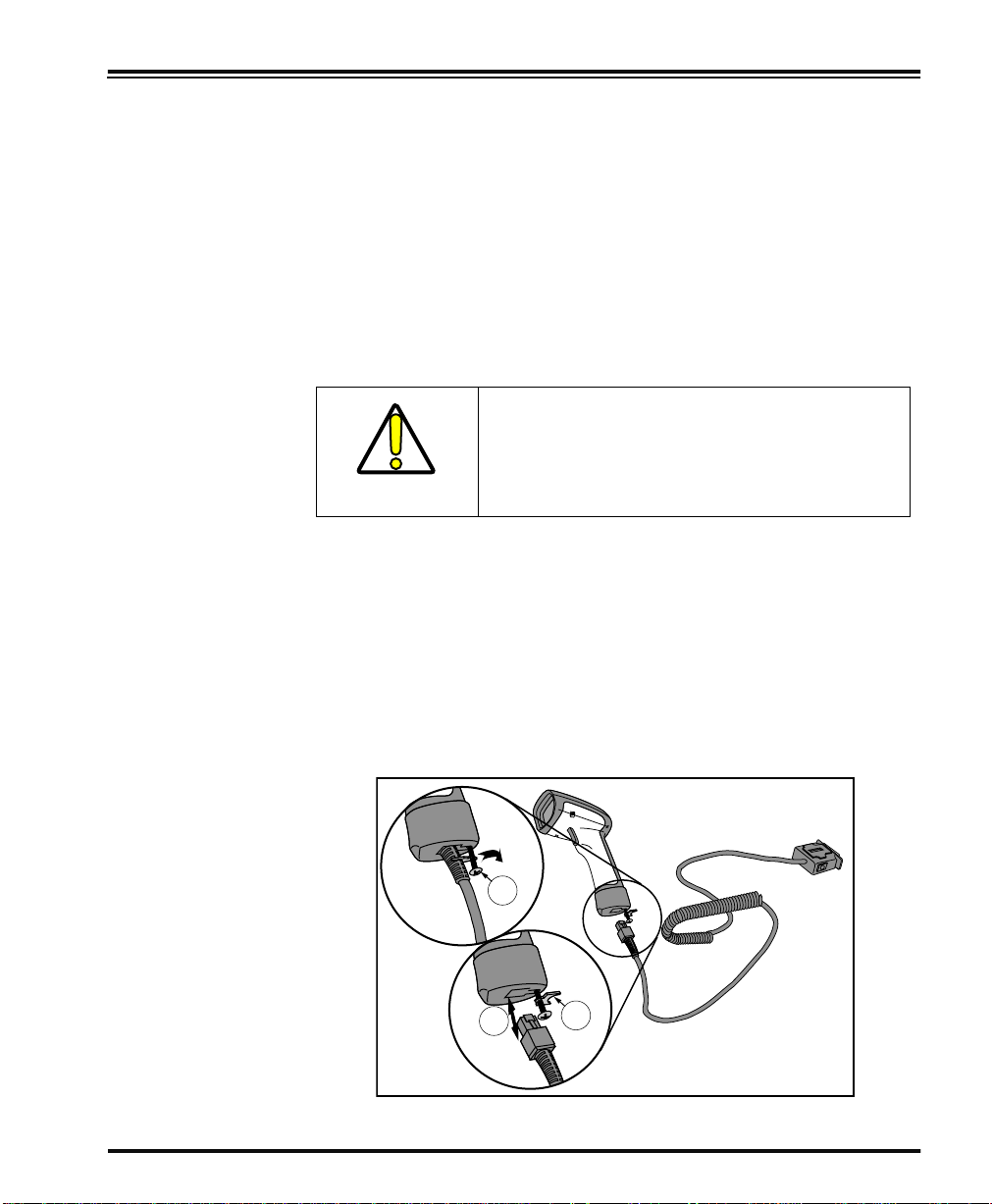
change your sc ann e r’s interface cable by following these instructions.
(Refer to Figure 1.):
1. Loosen the screw at the bottom of the handle. This screw is
captive and does not come all the way out.
DO NOT try to pull the end cap off, as this may
damage the scanner.
CAUTION
2. Swing the forked cable retainer clear of the square hole in the
end cap and rotate away from the cable.
3. Holding the scanner handle and end cap together in one hand,
pull the connector out of the handle end cap to free the interface cable.
4. Connect the new interface cable at the scanner and rotate the
forked cable retainer to secure it. Tighten the screw to between
6 and 10 in-lbs.
Figure 1. Removing/Replacing the Interface Cable
1
3
Programming Guide 3
2
Page 10

Software Verify that your scanner supports the desired interface
indicates the interface groupings the scanner supports. Contact your
nearest PSC service depot if you don’t know your scanner’s group, or
need assistance to change the scanner to another interface group.
The Standard Keyboard Wedge/Wand Emulation/RS-232 Group
supports:
• I/F Type A - PC/XT w/Alternate Key Encoding
• I/F Type B - AT, PS/2 25- 286, 30-286, 50, 50Z, 60, 70, 80, 90 & 95
w/Alternate Key Encoding
• I/F Type C - PS/2 25 and 30 w/Alternate Key Encoding
• I/F Type D - PC/XT w/Standard Key Encoding
• I/F Type E - AT, PS/2 25- 286, 30-286, 50, 50Z, 60, 70, 80, 90 & 95
w/Standard Key Encoding
• I/F Type F - PS/2 25 and 30 w/Standard Key Encoding
®
• I/F Type H - IBM
• I/F Type I - PS/555530T w/104 keyboard
• I/F Type J - NEC
• Wand Emulation
• RS-232
• WN
2
-RS-232 (SNI)
3xxx w/102 keyboard
®
9801 keyboard
1
. The list below
The IBM/RS-232 Group supports:
• IBM Port 5B • IBM Port E
• IBM Port 9B • RS-232
• IBM Port 17 • WN-RS-232
For interface groupings supported by the Universal [Keyboard] Wedge
Group:
• Consult the Universal Wedge Programming Guide for more infor-
mation.
1. Contact your dealer or sales representative if your desired interface is not listed. Interface group
definitions are subject to change without notice.
2. Wincor Nixdorf® (formally SNI)
4 PowerScan™ Scanner
Page 11
After familiarizing yourself with the basi c scanner programming procedures in this section, turn to the appropriate interface programming
section (RS-232, Wand Emulation, etc.) of this manual to set other interface features, completing the scanner’s conversion to a new interface
type.
Upon changing a scanner’s interface setting, scan a bar code to verify
that the scanner communicates correctly with the new host system.
Some sample bar codes are provided in Appendix B: Sample Bar Codes
on page 145. If any changes to the scanner’s factory settings are
needed, consult Customizing Your Scanner’s Operation below.
Customizing Your Scanner’s Operation
Most scanner programming falls within three general categories:
• Interface Selection and Settings - are the mandatory settings
necessary to allow communication with your host terminal.
Examples of these settings are: RS-232 baud rate and parity.
Ensure that your planned modifications are compatible with the current interface. For example,
baud rate selections are only valid in the RS-232
interface. The scanner will sound an error tone
when scanning programming labels for features
NOTE
invalid to the current interface group.
• Symbology Selection and Settings - gives the scanner the
capability to autodiscriminate as few as one, and as many as all
available symbologies. For optimal scanner performance
enable only those symbologies required. Additionally the scanner may be programmed with the standard options available
for the various symbologies, such as check d igit, minimum
label length, fixed and variable length bar codes, QuadraLogic
Decoding, etc.
• General Feature Set tings - are feat ures common to all interface
types. Examples include beeper adjustments such as volume
and length, read verification settings, etc.
If you experience difficulties, have questions or require additional
information, contact your local distributor, or call your dealer or sales
representative.
Programming Guide 5
Page 12
Programming Overview
The scanner’s programmable feature settings can be modified to
accommodate your system’s unique requirements. These settings can
be communicated to the scanner in one of two ways:
1. Commands can be sent directly from the host. A limited set of
host command s are available. Refer to Appendix A: Additional
Information on page 143 for more details.
2. The easiest, most comprehensive way to program the scanner
is to use the Configurator Express™ On-Screen Programmining
Kit. Ask your dealer for more information about this product.
3. Programming bar code labels can also be used to modify the
scanner’s programmable settings. This manual provides the
bar code labels and instructions necessary to configure the
scanner’s features/options.
NOTE
What Is Programming Mode?
When you program the scanner using any of
the methods above, the scanner will store the
changes until reprogrammed or returned to
factory defaults.
Programming Mode is a state in which the scanner must be placed in
order to accept programming commands. When programming using
the bar code labels in this manual, the scanner is typically placed in
Programming Mode by scanning the “SET” label at the top of most
programming feature pages.
While in the Programming Mode, the scanner only recognizes the special programming bar codes contained in this programming guide. See
the section, LED and Beeper Indicators on page 11 for information about
scanner indications while in the Programming Mode.
6 PowerScan™ Scanner
Page 13
Programming Session
A typical programming session is conducted as follows:
1. Scan the SET bar code at the beginning of each set of program-
ming bar codes to place the scanner in Programming Mode.
The scanner will emit three beeps, indicating it has read the bar
code and the green LED will flash on and off slowly while the
scanner remains in Programming Mode. Normal scann ing
functions are disabled.
2. Scan the programming label(s) that is (are) specially encoded
1
to make the desired changes. With few exceptions
, the scanner
will emit a triple beep each time you scan a valid programming
bar code.
Not all features are available for all interfaces
and the scanner will sound an error tone when
scanning programming bar codes for features
invalid to the current interface. Only features
supported by the currently active interface will
NOTE
be implemented.
If a label is scanned that changes the scanner’s interface, all previous configuration
items scanned in the programming session
NOTE
are lost.
Additionally, when programming a feature requiring you to scan single digits to set a multi-digit number, such as Minimum Label Length,
scanning the END bar code (or any item tag/item value bar code)
before completing all input will result in an error tone and cause the
scanner to exit Programming Mode. Under these circumstances, the
current feature you were trying to set is thrown out; any previous bar
codes scanned during the session will take effect.
1. Some features, such as Minimum Label Length, require you to select the label’s length by scanning a series of single-digit bar codes. A single ‘good read’ beep is soun d ed wh en sc an n in g th es e
single digits in Programming Mode. Only the final required digit in the sequence will produce a triple beep when scanned, indicating a successfully programmed feature.
Programming Guide 7
Page 14

It is recommended that programming sessions be limited to one feature at a time.
Should you make a mistake in the programming sequence, it can be difficult to discover
where an error has been made if several features are programmed at once. Additionally, it
NOTE
3. Scan the END label at the bottom of the page to save any new
settings and exit Programming Mode. The scanner will sound
a beep and reset upon exiting Programming Mode, and the
green LED will return to its usual state (on steady or off).
The scanner will not exit Programming Mode unless the END
bar code is scanned or power is disconnected. Disconnecting
power during Programming Mode, before scanning the END
label, will cause all new settings to be ignored. On power-up,
the scanner will return to previous settings.
4. Maintain a good record of all changes made to ensure that you
know if the original factory settings have been changed.
can be confusing to determine which features
may or may not have been successfully set
following such a session.
8 PowerScan™ Scanner
Page 15

Programming
Sequence
To modify a scanner feature (item), the programming bar codes contained in this manual must be scanned in a given sequence depending
upon the feature being programmed (as shown in Table 1). There are
three possible programming sequences:
A. Programming sample A (the most commonly used format)
demonstrates how three bar codes are scanned in sequence to
do the following:
1. Place the scanner in Programming Mode (SET bar code).
1
2. Scan the Item Tag
that will enable the new feature.
3. End the programming session and reset the scanner (E ND
bar code).
B. Sample B provides an example of a programming feature
requiring the entry of a range value. Like sample A, the scanner is placed in Programming Mode and an Item Tag
1
is
scanned. Then, a value must be entered before ending the programming session. In the example, three digits must be
scanned fr om th e nu mber p ad in Appendix C : Ke ypad. This type
of format, requiring a total of as many as six programming bar
codes, is necessary to allow flexible programming with larger
item value numeric ranges.
C. The programming sequence shown in example C requires
scanning of a single, extended length bar code. This special
programming bar code contains all the data necessary to enter
1
Programming Mode, set the Item Tag
and Item V alue, and exit
Programming Mode (all in one step).
1. An “Item Tag” is a term used to describe an assigned number, which is encoded in a programming
bar code, that toggles (selects, enables, disables, etc.) a specific programming feature.
Programming Guide 9
Page 16
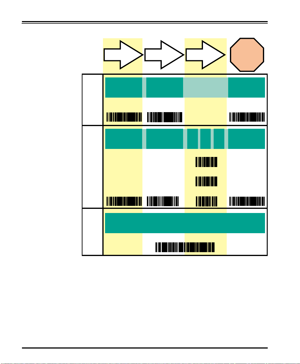
Table 1. Programming Sequence
A
B
C
SET
1
SET
ITEM T AG ITEM VALUE END/RESET
23
ENABLE
NEW FEATURE
END
123456
0
ENABLE NEW
FEATURE
USING THE
FOLLOWING
SET END
SETTINGS...
0
8
1
ONE BAR CODE CONTAINS SET + ITEM T AG + ITEM VALUE + END
10 PowerScan™ Scanner
Page 17

LED and Beeper Indicators
The scanner provides a set of indicators that verify/announce the various scanner functions.
LED Indicators The Amber “Laser ON” LED (located on top rear of scanner)
- lights whenever laser power is on.
The Green “Good Read” LED (also located on top rear of scanner)
- Flashes
- Flashes
gramming Mode.
The Beeper While in Scanning mode...
-Sounds
-Sounds
-Sounds
While in Programming mode...
-Sounds
Mode.
-Sounds
feature.
1
once to indicate when a “good read” has occurred.
1
slowly on and off to indicate the scanner is in Pro-
1
four times at power-up.
1
once following a “good read.”
1
six rapid “chirps” to indicate an error (error tone).
1
one time when entering/exiting the Programming
1
three times to indicate a successfully programmed
1. The green LED and Beeper are configurable features and may have been modified or disabled at
an earlier programming session. See the section in this manual titled
more details.
General Features for
Programming Guide 11
Page 18
If You Make a Mistake...
If, during a programming session, you find that you are unsure of the
scanner’s settings or wish to reset the scanner’s configuration, use the
Return to Factory Settings label below to return the scanner’s configuration to the factory settings. Scannin g this label will also reset any
changes made during previous programming sessions.
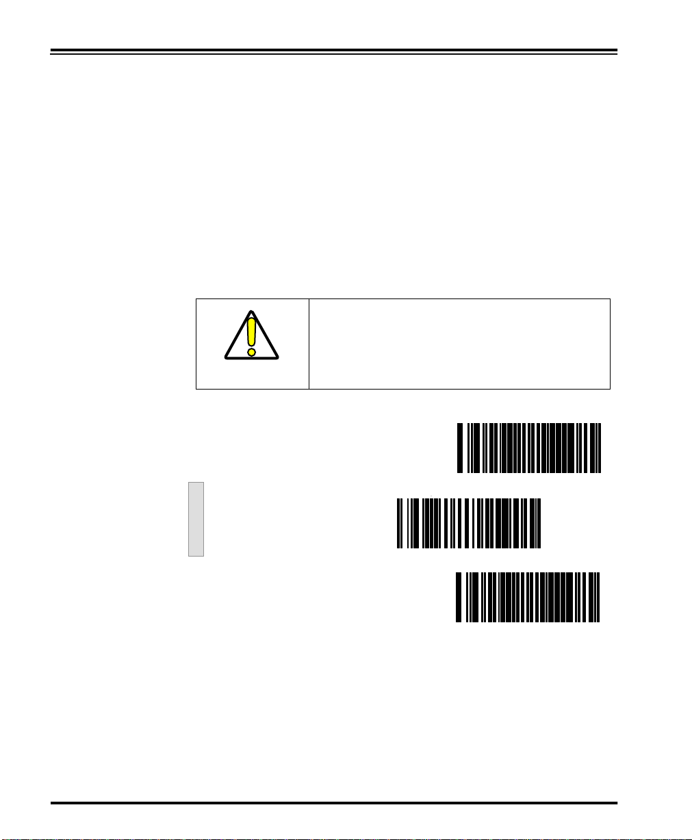
Return to Factory Settings
Scan this label to return the scanner to the default settings configured
at the factory. This label is typically used to return the scanner to a
“known” operating state when the present programming status is not
known, faulty, or suspect.
CAUTION
SET ----------------------- --------------------
Use this label with caution, since it will reset
ALL features that may have been programmed
for that interface type since the scanner’s
installation.
Return to Factory Setting ---------
END ------------------------------------------
If you don’t have a rec or d of yo ur s ite /s ys te m’s original configuration,
you may need to contact your sale representative for assistance to
return the scanner to normal function. Please be prepared to provide
information about the company, location, host terminal system and
other pertinent information about the scanner being repaired.
12 PowerScan™ Scanner
Page 19

Where To Go From Here
Programming is easy and straightforward if you fol low these steps:
NOTE
1. If you are changing the scanner’s interface type, follow the
instructions in the section titled, Changing Interfaces on page 2
before proceeding.
2. Scan any feature bar codes that are unique to the interface you
are currently programming. These interface specific programming bar codes immediately follow each interface selection
label.
3. Turn to Symbologies Supported on page 60 if you are going to
change any bar code symbologies o r modify any symbologyrelated features.
If you are changing some interface types (for
example; if you are mo ving th e scanner f r om a
Universal Keyboard Wedge to an RS-232 host)
you must first change the hardware. Replace
the scanner’s interface board (if required) and
connect the scanner using the new interface
cable BEFORE performing any programming
changes.
4. Turn to General Features on page 130 if you wish to change or
modify any of the scanner’s other features.
Once the necessary changes have been made, and you have scanned
the END bar code, you are ready to scan.
Programming Guide 13
Page 20

Interface Selection
This section contains programming bar code labels to select the
following interfaces:
• Wand Emulation Interface
• Pre-Noise Settings
• Keyboard Wedge Interface
• IBM Interface
Wand Emulation Interface
Scan these labels to enable the Wand Emulation Interface.
SET ----------------------- --------------------
Enable Wand Emulation ---------
END ------------------- ---------------- -------
14 PowerScan™ Scanner
Page 21
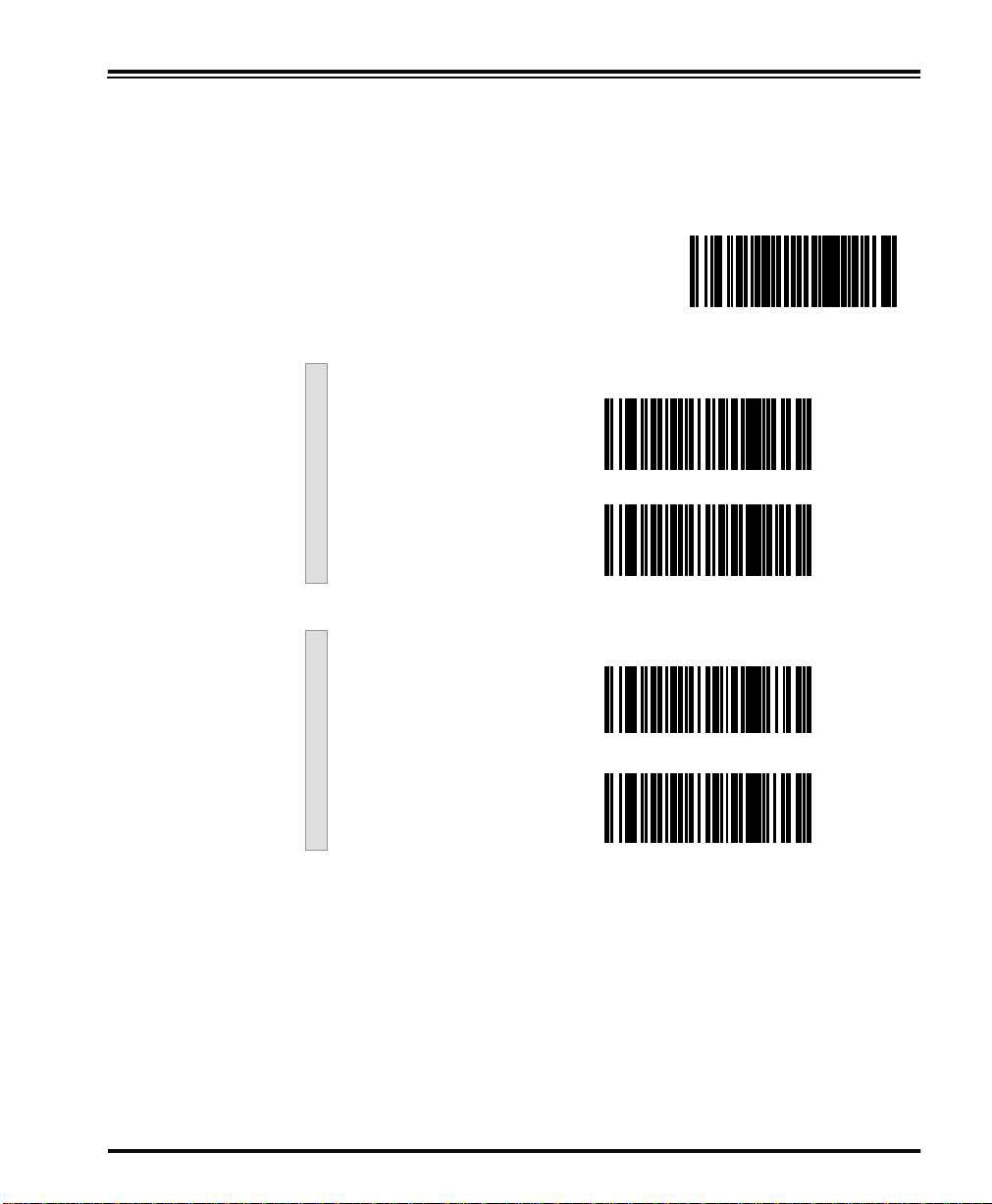
Wand Emulation Settings
Use these programming bar codes to configure the settings for the
Wand Emulation Interface.
SET ----------------------- --------------------
Polarity
Space Low, Bar High ---------
Space High, Bar Low ---------
Signal Speed
Low (660 µs) ---------
High (330 µs) ---------
Programming Guide 15
Page 22

Data Format
Transmit in Normal
Format ---------
Transmit in C39
Format ---------
Transmit in C39 Full ASCII
Format ---------
Transmit in C128
Format ---------
Idle State
Low ---------
High ---------
16 PowerScan™ Scanner
Page 23

Transmit C128 Function
Characters
a
Enable
Disable ---------
---------
END ------------------- ---------------- -------
a. This feature should only be enabled when the Wand Data Format is con-
figured for Transmit in Normal Format or Transmit in Code 128 Format.
Programming Guide 17
Page 24

Wand
Emulation Pre/
Post-Noise
Settings
The number of noise transitions generated prior to or following label
transitions are independently configurable options. To set either pre- or
post-noise transitions, enter Programming Mode by scanning the SET
bar code, then follow these steps:
1. Scan Don’t Transmit Pre-Noise or Don’t Transmit Post-Noise,
followed by the END bar code to disable noise transitions, or...
2. Scan the Set Pre- or Post -Noise Transitions bar code followed
by the digits from Appendix C: Keypad that represent the
desired number of noise transitions. Select from one to twenty
noise transitions for either pre- or post-noise. Complete the
programming sequence by scanning the END bar code.
Settings for this feature have been enhanced
since the product was originally released, adding the option to select a specific quantity of
noise transitions. If your scanner has a date
code of February, 2001 or before, pre-noise/
post-noise transitions are enabled by following
Step 2 above, EXCEPT the single digit selected
from Appendix C: Keypad MUST be one (1).
NOTE
This will either set the pre-noise transitions to
one or the post-noise transitions to three
depending on which feature is being programmed. The feature is disabled in the same
manner as Step 1 above.
1
Pre-Noise
Settings
SET ----------------- --------------------------
Pre-Noise
Don’t Transmit
Pre-Noise ---------
1. Scanners with a date code of February of 2001 or before MUST select the digits zero-one (01).
See the note on this page for details.
18 PowerScan™ Scanner
Page 25
Post-Noise Settings
Set Pre-Noise Transitions ---------
Scan two digits representing the desired number of Pre-Noise Transitions
using the number pad from Appendix C: Keypad, padded with leading zeros
(example: 03 = three transitions, 08 = eight, 15 = fifteen, etc.)
END ----------------- ----------- ------------ --
SET ----------------- --------------------------
Post-Noise
Don’t Transmit PostNoise ---------
Set Post-Noise Transitions ---------
Scan two digits representing the desired number of Post-Noise Transitions
using the number pad from Appendix C: Keypad, padded with leading zeros
(example: 03 = three transitions, 08 = eight, 15 = fifteen, etc.)
END ----------------- ----------- ------------ --
Programming Guide 19
Page 26

RS-232 Interface/WN-RS-232 (SNI) Interface
Scan these labels to enable either the standard RS-232 interface
(PSC RS-232) or the WN-RS-232 (SNI) Interface.
SET ----------------------- --------------------
Enable Standard
RS-232 ---------
Enable WN-RS-232 ---------
END ------------------- ---------------- -------
RS-232 Communication Parameters
This section contains the following RS-232 communication parameters
in the order listed:
• Baud Rate
• Data Format Settings
- Data Bit
- Parity Bit
- Stop Bit(s)
• Handshaking
- Hardware Handshaking (CTS/RTS)
- Software Handshaking (Xon/Xoff)
• ACK/NAK Options
• Intercharacter Delay
Go to the sections titled Symbology Select ion starting on page 63 and
General Features on page 130 if you want to change any other settings
for this interface.
20 PowerScan™ Scanner
Page 27
Baud Rate Use the bar codes on this page to select the communications Baud Rate.
Only one Baud Rate selection may be active at any one time. The last
Baud Rate label you scan during a programming session will be the setting that is stored when you scan the END label.
SET ----------------------- --------------------
Baud Rate = 1200 ---------
Baud Rate = 2400 ---------
Baud Rate = 4800 ---------
Baud Rate = 9600 ---------
Baud Rate = 19200 ---------
Baud Rate = 38400 ---------
END ------------------- ---------------- -------
Programming Guide 21
Page 28
Data Format
Settings
The bar codes on this page can be used to select the data format configuration needed to communicate with your system. Refer to Table 1,
RS-232 Data Format below for acceptable combinations of these setting.
Data Format
Table
There are many possible data format configurations for an RS-232
interface. Check your host system manual to find out your system’s
communications requirements.
Table 1. RS-232 Data Format
Data Bit Parity Bit Stop Bit(s) Start Bit
Seven 0 2 1
Seven 1 1 1
Seven 1 2 1
Eight 0 0 1
Eight 0 2 1
Eight 1 1 1
Use these bar codes to set the Data Format options desired.
SET ----------------------- --------------------
Data Bit
Seven ---------
Eight ---------
22 PowerScan™ Scanner
Page 29
Parity Bit
None ---------
Even ---------
Odd ---------
Mark ---------
Space ---------
Stop Bit(s)
One ---------
Two ---------
END ------------------- ---------------- -------
Programming Guide 23
Page 30
Handshaking Review your system documentation to identify handshaking require-
ments, and use these labels to change the settings if required. The following brief descriptions explain each selection.
Hardware
Handshaking
CTS/RTS Flow Control - is hardware handshaking. The scanner acti-
vates the RTS (Request to Send) line when it is ready to send data to the
host. The scanner waits for an active Clear to Send (CTS) signal from
the host before transmitting data. If hardware control is disabled, CTS/
RTS communication will not take place. If the host deactivates the CTS
line during data transmission, the host will receive additional characters for no more than 2ms
1
.
CTS/RTS Flow Control
Data
CTS
Label Transmission Label TransmissionXmission
Active
Disabled
Inactive
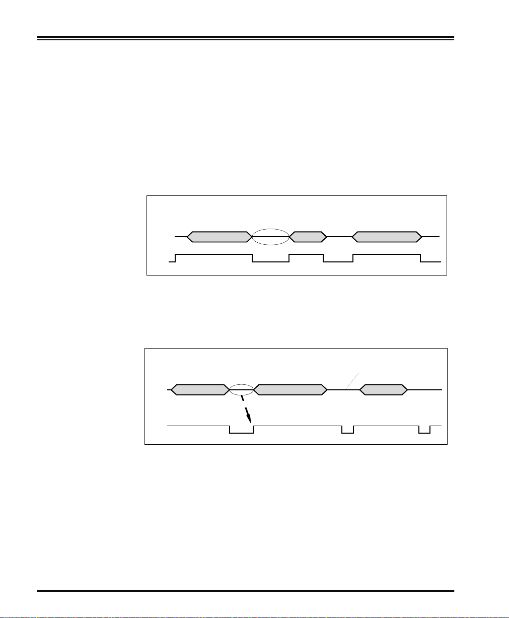
CTS Scan Control - is also a hardware handshaking. When scan con-
trol is enabled, label scanning is disabled until CTS is asserted and deasserted as illustrated below.
Data
CTS Scan Control
Label 1 Label 2Label 1
Disabled until
Will not scan again
until toggled
Assert
CTS
1. Timing varies slightly depending upon the baud rate selected.
De-assert
24 PowerScan™ Scanner
Page 31

Handshaking controls are mutually exclusive. The settings below
allow only one of these features to be enabled at a time, as enabling
multiple controls will produce unpredictable results.
Each of the handshaking features requires
that a series of bar codes (Step #1, Step #2) in
the sequence given. That is, you must enter
Programming Mode by scanning the SET bar
code, scan the bar codes required to set one
NOTE
handshaking feature, then scan the END bar
code.
Scan the SET bar code label then the Step #1, Step #2 below, followed
by the END bar code labels to enable CTS/RTS Flow Control.
Enable CTS/RTS Flow Control
SET ----------------------- --------------------
Step #1 ---------
Step #2 ---------
END ------------------- ---------------- -------
Programming Guide 25
Page 32

Scan the SET bar code label then the Step #1, Step #2 below, followed
by the END bar code labels to enable CTS Scan Control.
Enable CTS Scan Control
SET ----------------------- --------------------
Step #1 ---------
Step #2 ---------
END ------------------- ---------------- -------
26 PowerScan™ Scanner
Page 33

Software
Handshaking
Xon/Xoff - is software handshaking that allows the host to control data
transmission. If the host sends an Xoff command to the scanner, the
scanner will not send the bar code data until it receives an Xon command from the host. If the host sends the Xoff command during data
transmission, the host will receive additional characters for no more
1
than 2ms
.
Scan the SET bar code label then the Step #1, Step #2 below, followed
by the END bar code labels to enable Xon/Xoff Control.
Enable Xon/Xoff Control
SET ----------------------- --------------------
Step #1 ---------
Step #2 ---------
END ------------------- ---------------- -------
1. Timing varies slightly depending upon the baud rate selected.
Programming Guide 27
Page 34

Disable both CTS/RTS and Xon/Xoff Controls - disables both the
CTS/RTS and Xon/Xoff software controls.
Scan the SET bar code label then the Step #1, Step #2 below, followed
by the END bar code labels to disable both CTS/RTS and Xon/Xoff
Control.
To disable either CTS/RTS or Xon/Xoff, you
must first DISABLE BOTH CRTS/RTS and Xon/
Xoff Control using the programming labels
below. Then ENABLE the desired handshak-
NOTE
Disable both CTS/RTS and Xon/Xoff Control
SET ----------------------- --------------------
Step #1 ---------
ing feature from page25 or page 27.
Step #2 ---------
END ------------------- ---------------- -------
28 PowerScan™ Scanner
Page 35

RS-232 ACK/
NAK Options
Several ACK/NAK parameters can be set for your scanner.
Options for RS-232 ACK/NAK are:
• Disable ACK/NAK
• Enable ACK/NAK for bar code transmission
• Enable ACK/NAK for host command acknowledge
• Enable ACK/NAK for bar code transmission and host com-
mand acknowledge
RS-232 ACK/NAK Options
SET ----------------------- --------------------
Disable ACK/NAK ---------
Enable for Bar Code
Transmission ---------
Enable for Host Command
Acknowledge ---------
Enable for Bar Code
Transmission and
Host Command
Acknowledge ---------
END ------------------- ---------------- -------
Programming Guide 29
Page 36

RS-232
Intercharacter
Delay
Intercharacter Delay refers to the pause, if any, between each character
before it is sent to the host. This time delay is used to control the flow of
data from the scanner.
SET ----------------------- --------------------
None ---------
10 Milliseconds ---------
20 Milliseconds ---------
30 Milliseconds ---------
40 Milliseconds ---------
50 Milliseconds ---------
100 Milliseconds ---------
30 PowerScan™ Scanner
Page 37

200 Milliseconds ---------
500 Milliseconds ---------
1 Second ---------
END ------------------- ---------------- -------
Programming Guide 31
Page 38

Keyboard Wedge Interface
This section contains the following PC Keyboard Wedge interface
parameters in the order listed:
• Interface Selection
• Connect to a Laptop
• Caps Lock
• Country Mode
• Intercharacter Delay
• Quiet Interval
Go to the sections titled Symbology Select ion starting on page 63 and
General Features starting on page 130 if you want to change any oth er
settings.
NOTE
If the transmission parameters are configured
such that a label results in no actual data to
send, the label will be accepted, beeped, and
no data transmitted.
32 PowerScan™ Scanner
Page 39

PC Keyboard
Wedge
Interface
Selection
This scanner supports a variety of PC Keyboard interfaces. The table
below defines the different interface selections. Scan the corres ponding
bar code starting on page 34 to select the desired keyboard interface.
I/F Type PCs Supported
A PC/XT w/Alternate Key Encoding
B
C PS/2 25 and 30 w/Alternate Key Encoding
D PC/XT w/Standard Key Encoding
E
F PS/2 25 and 30 w/Standard Key Encoding
G IBM 3xxx w/122 keyboard
H IBM 3xxx w/102 keyboard
I PS/55 5530T w/104 keyboard
J NEC 9801
NOTE
AT, PS/2 25-286, 30-286, 50, 50Z, 60, 70, 80, 90 & 95
w/Alternate Key Encoding
AT, PS/2 25-286, 30-286, 50, 50Z, 60, 70, 80, 90 & 95
w/Standard Key Encoding
We recommend that you disconnect power
before plugging/unplugging cables to avoid
any possibility of equipment damage.
Programming Guide 33
Page 40

Scan the bar codes corresponding to the applicable Keyboard type
listed on page 33.
PC Keyboard Interface Type
SET ----------------------- --------------------
A ---------
B ---------
C ---------
D ---------
E ---------
F ---------
G ---------
34 PowerScan™ Scanner
Page 41

H ---------
I ---------
J ---------
END ------------------- ---------------- -------
Programming Guide 35
Page 42

Connect to a
Laptop/No
Keyboard
Attached
If no keyboard is attached, the scanner must provide the acknowledge
signal to the PC. In this case, enable the "Laptop/No External Keyboard" mode. If a keyboard is attached, enable "Keyboard Attached."
Laptop (integrated keyboard) -provides the acknowledge signal to the
PC when the scanner is connected to a laptop computer or when the
scanner is operated with no external keyboard.
PC (external keyb oard) - is enabled when the scan ner is connected to a
standard PC."
Send Control Characters - transmits all ASCII characters except NUL
(00h) . Disabling this feature limits transmission of ASCII characters to
the following:
• Only ASCII characters between 20h..127h, plus.
- Carriage Return (CR=0Dh)
- BackSpace (BS=08h)
-Right Tab (HT=09h)
-Left Tab (0Bh)
-Esc (1Bh)
Send Function Character - transmits characters between 00H - IFH
which are not in the normal ASCII set.
Scan the bar code belows below to select the applicab le option for con-
necting to a laptop or PC.
SET ----------------------- --------------------
Connect to Laptop or PC
Laptop/No external
Keyboard ---------
Keyboard Attached ---------
36 PowerScan™ Scanner
Page 43

Send Control/Function
Characters
Enable Control
Characters ---------
Enable Function
Characters ---------
Disable ---------
END ------------------- ---------------- -------
Programming Guide 37
Page 44

Caps Lock Three caps lock settings are available. These are:
• Caps Lock Off - sends character data (to the host in normal for-
mat.
• Caps Lock On - sends character data (to the host) in reverse
case:
(a.z) = (A .Z)
(A.Z) = (a .z)
Use this feature if your keyboard’s caps lock key is on.
• Caps Lock = Shift-Lock - sends character data (to the host) in
shifted case. Use this feature if you choose to use the keyboard
with the shift lock key left on. For use with interface type G
(IBM 3xxx 122-keyboard) ONLY.
SET ----------------------- --------------------
Caps Lock OFF ---------
Caps Lock ON ---------
Cap Locks = Shift Lock ---------
END ------------------- ---------------- -------
38 PowerScan™ Scanner
Page 45

Country Mode The following country/languages can be selected when configured for
I/F Type E only:
• USA • France • Portugal • Japanese 1 06-Key
• Belgium • Germany • Spain
• Britain • Italy • Sweden
• Denmark • Norway • Switzerland
Scan the bar code below to selected the desired country.
SET ----------------------- --------------------
USA ---------
Belgium ---------
Britain ---------
Denmark ---------
France ---------
Programming Guide 39
Page 46

Germany ---------
Italy ---------
Norway ---------
Portugal ---------
Spain ---------
Sweden ---------
Switzerland ---------
Japanese 106-Key ---------
END ------------------- ---------------- -------
40 PowerScan™ Scanner
Page 47

Keyboard
Wedge
Intercharacter
Delay
Intercharacter Delay refers to the pause, if any, between each character
before it is sent to the host. This time delay is used to control the flow of
data from the scanner . Use these labels to select the desired Intercharacter Delay.
SET ----------------------- --------------------
None ---------
5 Milliseconds ---------
10 Milliseconds ---------
20 Milliseconds ---------
30 Milliseconds ---------
40 Milliseconds ---------
60 Milliseconds ---------
Programming Guide 41
Page 48

80 Milliseconds ---------
90 Milliseconds ---------
END ------------------- ---------------- -------
42 PowerScan™ Scanner
Page 49

Quiet Interval Quiet Interval is the amount of time to look for keyboard activity
before the scanner breaks the keyboard connection in order to transmit
data to the host.
SET ----------------------- --------------------
10 Milliseconds ---------
20 Milliseconds ---------
50 Milliseconds ---------
100 Milliseconds ---------
200 Milliseconds ---------
500 Milliseconds ---------
1 Second ---------
END ------------------- ---------------- -------
Programming Guide 43
Page 50

IBM Interface
The IBM Group supports:
• Port 5B
• Port 9B
• Port 17
• Port E
Scan the SET bar code to enter the programming mode, then scan the
programming bar code below to activate the desired interface, followed by the END bar code to exit the programming mode and reset
the scanner.
SET ----------------------- --------------------
Enable Port 5B ---------
Enable Port 9B ---------
Enable Port 17 ---------
Enable Port E ---------
END ------------------- ---------------- -------
44 PowerScan™ Scanner
Page 51

Transmit
Labels in Code
39 Format
When this feature is enabled, the symbology identifier for the specified
label will be set to Code 39 and the label will be transmitted. No data
checking or conversion is done. Table 2 below shows the symbologies
converted.
Table 2. Symbologies Converted to Code 39
Port Symbology Converted
Port 5B Code 128, Code 93, Codabar
Port 9B Code 93, Codabar
Port 17 No Effect
Port E No Ef fect
Scan the bar codes below to enable/disable the Conversion to Code 39
option.
SET ----------------------- --------------------
Enable Conversion to
Code 39 ---------
Disable Conversion to
Code 39 ---------
END ------------------- ---------------- -------
Programming Guide 45
Page 52

Label Transmit Configuration (RS-232 and Keyboard Wedge Interfaces only)
If you need to send information in addition to bar code label data, the
scanner can be configured to transmit Global Prefixes (also known as
preambles), Global Suffixes (also known as p ostambles), and symbology specific identifier characters (termed Label I.D.).
Prefix, Suffix, and Label I.D.
The table below shows examples of how Prefix, Suffix, and Label I.D.
characters can be applied.
Column three contains the label data, while columns one, two, four
and five contain the additional characters added by way of the Prefix,
Label I.D. as Prefix, Label I.D. as Suffix, and Global Suffix respectively.
The last column shows the resulting data that will be transmitted when
the additional characters are applied.
Using this feature requires a thorough understanding of your specific system requirements. If you
have questions or need assistance with these features, call your system specialist or PSC technical
NOTE
support.
Table 3. Prefix, Suffix, Label I.D. Examples
Global
Prefix
(00 = No
Char.)
1st
Char
00 00 None 0998875 None 00 00 0998875
50 51 None 0011223344 None 000 000 PQ0011223344
00 00 46 46 00210126 None 00 00 FF00210126
50 51 41
00 00 None $99.95 25
50 51 None 998875 25
00 00 None 101234567891 None 53 57 10123456789SW
50 51 None Code39Test None 53 57 PQCode39TestSW
00 00 45
50 00 45 46 0998875 None 53 57 PFF09988875SW
00 00 None 0998875 46 46 53 57 0998875FFSW
50 51 None 0011223344 46 00* 53 57 PQ0011223344FSW
a. No second character
2nd
Char
Label I.D. as
Prefix
1st
Char
2nd
Char
00
00
Label Data
(Examples)
a
00210126 None 00 00 PQA210126
a
Code128 None 53 00 ECode128S
Label I.D. as
Suffix
1st
Char
Global Suffix
(00 - No
Char)
2nd
1st
Char
Char
Char
a
00 00 $99.95%
00
a
00 00 PQ998875E
00
2nd
Resulting Label
Format
46 PowerScan™ Scanner
Page 53

Setting Global
Prefix(es)
One or two prefix characters may be added to the standard label format when desired. For the addition of mor e than two prefix characters,
contact your distributor or technical support representative for Full
Label Edit (FLE) options.
Identify your specific system requirements before adding or modifying
these settings, then follow these steps:
1. Look at the ASCII chart shown on the inside back cover of this
manual, and identify the ASCII character(s) and the corresponding Hex Code(s) for the ASCII characters you will use as
prefixes.
For example, if you are going to send two prefix characters as ‘STX’
(start transmit) and ‘SP’ (Space), the ASCII chart shows that ‘STX’
equals 02 hex and ‘SP’ equals 20 hex.
2. Scan the SET bar code on page 48.
3. Scan the SET PREFIX bar code.
4. Turn to Appendix C: Keypad on page 147, and scan the four dig-
its corresponding to the hex values determined in step one
above. (For the example, scan 0, 2, 2, 0). Return to this page and
go to step five.
Successful programming of a prefix requires 4
digits.
NOTE
If you make a mistake or lose your place while
setting this option, scan the END bar code to
exit Programming Mode. The scanner will
sound a two-beep error tone to indicate that
NOTE
5. Scan the END bar code.
You have added a two character prefix to all bar code data, regardless
of label symbology, that will be added to the label data before it is sent
to the host.
programming was incomplete, and the setting
will remain as it was before entering Programming Mode.
Programming Guide 47
Page 54

Setting Global Prefix(es)
SET ----------------------- --------------------
Set Prefix ---------
END ------------------- ---------------- -------
Setting Global
Suffix(es)
One or two suffix characters may be added to the standard label format
when desired. For the addition of more than two suffix characters, contact your distributor or technical support representative for Full Label
Edit (FLE) options.
Identify your specific system requirements before adding or modifying
these settings, then follow these steps:
1. Look at the ASCII chart shown on the inside back cover of this
manual, and identify the ASCII character(s) and the corresponding Hex Code(s) for the ASCII characters you will use as
suffixes.
For example, if you are going to send two suffix characters as ‘LF’ (Line
Feed) and ‘CR’ (Carriage Return). The ASCII chart shows that ‘LF’
equals 0A hex and ‘CR’ equals 0D hex.
2. Scan the SET bar code on page 49.
3. Scan the Set Suffix bar code.
4. Turn to Appendix C: Keypad on page 147, an d scan the four dig-
its corresponding to the Hex Values determined in step one
above. (For the example, scan 0, A, 0, D). Return to this page
and go to step five.
48 PowerScan™ Scanner
Page 55

Successful programming of a suffix requires
4 digits.
NOTE
If you make a mistake or lose your place while
setting this option, scan the END bar code to
exit Programming Mode. The scanner will
sound a two-beep error tone to indicate that
programming was incomplete, and the setting
NOTE
5. Scan the END bar code.
You have added a two character suffix to all bar code data, regardless
of label symbology, that will be added to the label data before it is sent
to the host
SET ----------------------- --------------------
.
Setting Global Suffix(es)
will remain as it was before entering Programming Mode.
Set Suffix ---------
END ------------------- ---------------- -------
Programming Guide 49
Page 56

Single
Character
Prefix or Suffix
The scanner will not transmit a prefix, or suffix character if its hex
value is set to zero. To set a prefix or suffix that has only one character,
follow these steps:
1. Scan the SET bar code on page 51.
2. Scan SET PREFIX or SET SUFFIX bar code.
3. Turn to the keypad (Appendix C: Keypad on page 147) and scan
the two-digit hex code that represents your desired character
(refer to the ASCII chart on the inside back cover of this manual for this conversion).
4. Scan the digit ‘0’ two times to disable transmission of a second
character.
For example, if ‘Space’ (SP) is desired, the chart shows that the corresponding hex code for ‘SP’ is 20, thus you would scan the digit 2, then
the digit 0 for the first character, followed by 00 digits from the keypad
for the second character, (e.g., scan 2,0,0,0). Return to this page and go
to step five.
Successful programming of a prefix or suffix
requires 4 digits.
NOTE
If you make a mistake or lose your place while
setting this option, scan the END bar code to
exit Programming Mode. The scanner will
sound a two-beep error tone to indicate that
NOTE
5. Scan the END bar code on page 51.
programming was incomplete, and the setting
will remain as it was before entering Programming Mode.
50 PowerScan™ Scanner
Page 57

Setting a Single Character Prefix/Suffix
SET ----------------------- --------------------
Set Prefix ---------
Set Suffix ---------
END ------------------- ---------------- -------
Programming Guide 51
Page 58

Disabling
Prefix or Suffix
To disable global prefix or suffix characters, follow these instructions:
1. Scan the SET bar code below.
2. Scan SET PREFIX or SET SUFFIX.
3. Scan the digit ‘0’ four times to disable the prefix or suffix char-
acters. Go to step four.
4. Scan the END bar code.
Disabling Global Prefix/Suffix Characters
SET ----------------------- --------------------
Set Prefix ---------
Set Suffix ---------
0 ---------
END ------------------- ---------------- -------
52 PowerScan™ Scanner
Page 59

Setting Label
I.D.
Setting the Label I.D. feature can be a complex task requiring multiple
steps to enable all necessary options. You’ll want to familiarize yourself
with the contents of this section before proceeding. Here is a brief listing of the order of its contents:
• Label Identifiers
• Setting Label I.D. Locations
• Setting Label I.D. Characters by Symbology
• Label I.D. Symbology Selection
• Setting Single Character Label I.D.
• Disabling Label I.D. for a Specific Symbology
Label
Identifiers
Symbology-specific label identifiers comprise one or two ASCII characters that can precede or follow bar code label data as it is transmitted to
the host. The host may use these characters as a means of distinguishing between symbologies.
Industry standards have been established for symbology-specific label
identifiers, and are listed in the table below. Most scanners will have
factory default identifiers preset to these standards.
Table 4. Industry Standard Label Identifiers (all are prefixes)
Symbology ID Symbology ID
UPC-A A EAN-8 (8 Add-ons) FF
UPC-E E EAN-13 (2 Add-ons) F
EAN-8 FF EAN-13 (5 Add-ons) F
EAN-13 F EAN-13 (8 Add-ons) F
UPC-A (2 Add-ons) A Code 39 *
UPC-A (5 Add-ons) A PharmaCode A
UPC-A (8 Add-ons) A Codabar %
UPC-E (2 Add-ons E Interleaved 2 of 5 i
UPC-E (5 Add-ons) E Standard 2 of 5 i
UPC-E (8 Add-ons) E Code 93 &
EAN-8 (2 Add-ons) FF Code 128 #
EAN-8 (5 Add-ons) FF UCC/EAN 128 None
MSI/Plessey @
Setting Label
I.D. Location
Use the following bar codes to choose the position where Label I.D.
characters will be placed in relation to scanned label data :
Programming Guide 53
Page 60

• None (no Label I.D.), (e.g., prefix, label data, suffix)
• Prefix (before), (e.g., prefix, label I.D., label data,
suffix)
• Suffix (after) , (e.g., prefix, label data, label I.D., suffix).
Your selection (prefix, suffix, or none) will
apply universally to all symbologies and cannot be individually selected for each.
NOTE
1. Scan the SET bar code.
2. Scan the bar code for the desired positio n .
3. Scan the END bar code.
Setting Label I.D. Location
SET ----------------------- --------------------
Label I.D. = None ---------
Position Label I.D. as
Prefix ---------
Position Label I.D. as
Suffix ---------
END ------------------- ---------------- -------
54 PowerScan™ Scanner
Page 61

Setting Label
I.D. by
Symbology
To set symbology-specific label id entifiers (Label I.D.):
1. Look at the ASCII chart on the inside back cover, and identify
the ASCII character(s) and the corresponding Hex Code(s) for
the ASCII characters you will use as identifiers.
For example: You need to change the Label I.D. for UPC-A to ‘A1’.
2. Scan the SET bar code on page 56.
3. Scan the bar code starting on page 56 representing the symbol-
ogy whose Label I.D. you wish to modify. Scan only one symbology type per programming session.
In our example, we would scan the ‘UPC-A’ symbology bar code.
4. Identify and scan the four digits from the Appendix C: Keypad
on page 147 that correspond to the Hex Values you determined
in step one above. Return to this page and go to step five.
The hex values from the ASCII chart that correspond to ‘A1’ from our
example are as follows: 41 hex = ‘A’, a nd 31 hex = ‘1’. Thus, we would
scan digit programming bar codes in this order: 4, 1, 3, 1.
5. Scan the END bar code on page 58.
Successful programming requires 4 digits for
the Label I.D.
NOTE
You have changed the default Label I.D. for UPC-A from ‘A’ to ‘A1’.
Programming Guide 55
Page 62

Label I.D.
Symbology
Selection
Scan the bar code representing the symbology whose label you want to
modify. Scan only one symbology type per programming session.
Setting Label I.D. Characters by Symbology
SET ----------------------- --------------------
Code 39 ---------
PharmaCode 39 ---------
Code 128 ---------
UCC/EAN 128 ---------
Interleaved 2 of 5 ---------
Codabar ---------
UPC-A ---------
UPC-A w/2 digit
Add-ons ---------
56 PowerScan™ Scanner
Page 63

UPC-A w/5 digit
Add-ons ---------
UPC-A w/C128
Add-ons ---------
UPC-E ---------
UPC-E w/2 digit
Add-ons ---------
UPC-E w/5 digit
Add-ons ---------
UPC-E w/C128
Add-ons ---------
EAN-13 ---------
EAN-13 w/2 digit
Add-ons ---------
EAN-13 w/5 digit
Add-ons ---------
EAN-13 w/C128
Add-ons ---------
Programming Guide 57
Page 64

EAN-8 ---------
EAN-8 w/2 digit
Add-ons ---------
EAN-8 w/5 digit
Add-ons ---------
EAN-8 w/C128
Add-ons ---------
Code 93 ---------
Standard 2 of 5 ---------
MSI/Plessey ---------
END ------------------- ---------------- -------
58 PowerScan™ Scanner
Page 65

Setting Single
Character
Label I.D.
The scanner will not transmit a label I.D. character if its hex value is set
to zero. If you have determined that you need a Label I.D. that contains
only a single character, follow this modified procedure:
1. Scan the SET bar code on page on page 56.
2. Scan your selection from the list starting on page 56 for the
symbology identifier you plan to change.
For example, scan the EAN-8 bar code to select that symbology.
3. Turn to the keypad (Appendix C: Keypad on page 147) and scan
the two-digit hex code that represents your desired character
(refer to the ASCII chart on the inside back cover of this manual for this conversion).
4. Scan the digit ‘0’ two times to disable transmission of a
second character. Return to this page.
As an example, assume that you want to change the Label I.D. for
EAN-8 from the default setting “FF” to the single character “8”. In this
example, note that the chart shows that the ASCII character ‘8’ is eq ui valent to 38 hex, therefore the digits 3, then 8 should be scanned followed by two zeros (00) to indicate a single character I.D. (e.g., scan
3,8,0,0)
5. Scan the END bar code on page 58.
Successful programming requires 4 digits for
the Label I.D.
NOTE
If you make a mistake or lose your place while
setting this option, scan the END bar code to
exit Programming Mode. The scanner will
sound a two-beep error tone to indicate that
programming was incomplete, and the setting
Disabling
Label I.D. for a
NOTE
This procedure is the same as Setting Single Character Label I.D. above,
except you should scan four zeros before scanning the END bar code.
will remain as it was before entering Programming Mode.
Specific
Symbology
Programming Guide 59
Page 66

Symbologies Supported
Symbology selection (bar code type) de termines which symbologies
the scanner will decode. The char t below shows the symbologies that
are supported by each interface. Once you have identified the symbologies you wish to enable, turn to the following pages, enable those symbologies and set the data format options (e.g. check digit, start/stop
characters) required by your host system for each symbology type.
You must enable the symbology format options settings that are compatible with your host system.
The factory settings for each interface were chosen to meet the standard industry requirements and in most cases you will not need to
change the symbology format settings. If you are unsure of your system requirements, test the scanner using the factory settings before
making any changes.
= Supports this symbology
SYMBOLOGIES SUPPORTED
Code 39/PharmaCode
Code128
EAN 128
Interleaved 2 of 5
Codabar
UPC-A & E, EAN-13 & 8
UPC/EAN w/P2 Add-ons
UPC/EAN w P5 Add-ons
UPC/EAN w/C128 Add-ons
Code 93
Standard 2 of 5/IATA
INTERF ACE TYPE
MSI/Plessey
RS-232-STD
WN*-RS-232
Wand Emulation
Ke yboard Wedge
(all subtypes)
IBM Port 5B
IBM Port 9B
IBM Port 17
IBM Port E
*Wincor Nixdorf
60 PowerScan™ Scanner
Page 67

Symbology Overview
This section provides a brief descriptions of each of the many symbology features and opti ons available.
Enable Code 39 - selects Code 39 as an active symbology and allows
selection of Check Digit, Start/Stop and S ingle Digit options.
Enable PharmaCode 39 - is a symbology subset of Code 39. Enabling
PharmaCode 39 allows the scanner to read both PharmaCode 39 and
Standard Code 39 labels.
Enable Code 128 - selects Code 128 as an active symbology. The scan-
ner is preset to recognize all Code 128 bar codes that have between
1 and 50 characters.
Enable UCC/EAN 128 - chooses EAN 128 as an active symbology. The
Automatic Identification Manufacturers, Inc. of the United States (AIM
USA) have standardized the reporting of data sources from bar code
reading devices. Sending the AIM symbology prefix identifies the
symbology to the host terminal, allowing it to specifically differentiate
between UCC/EAN-128 (Code 128 with Function Character 1 in the
first position) and standard Code 128 symbo ls. When this feature is
disabled, the host cannot differentiate between these symbols.
Enable Interleaved 2 of 5 - selects Interlea ve d 2 of 5 as an active sym-
bology. Allows change of Check Digit or label format (fixed or variable
length) options.
Standard Code 39 must be enabled before
PharmaCode can be enabled.
NOTE
Enable Codabar - selects Codabar as an active symbology. Allows
selection of Check Digit, Start/Stop character an d fo rmat, or label format (fixed or variable length) options.
Enable UPC-A - enables UPC-A as an active symbology. If you enable
this symbology, additional options for symbology ex p ansion and reading add-ons are available.
Enable UPC-E - tells the scanner to recognize UPC-E as an active sym-
bology. Like UPC-A, UPC-E offers options for symbology expansion
and reading of add-ons.
Programming Guide 61
Page 68

Enable EAN-13 - selects EAN-13 as an active symbology. EAN-13
options are similar to those of the EAN-8 symbology.
Enable EAN-8 - selects EAN-8 as an active symbology. EAN-8 symbol-
ogy selection also allows options for symbology expansion and r eading
of add-ons.
Enable Code 93 - enables Code 93 as an active symbology. The scanner
is preset to recognize all Code 93 bar codes that have between 1 and 50
characters.
Enable Standard 2 of 5 - selects Standard 2 of 5 as an active symbology.
Options for this symbology are similar to Interleaved 2 o f 5
features.
IATA - is a special symbology subset of Standard 2 of 5. Enabling IATA
selects this custom code as the active Standard 2 of 5 symbology
(superseding any other Standard 2 of 5 features).
Standard 2 of 5 must be enabled in order for
IATA to be active, however, when IATA is
enabled, Standard 2 of 5 will not be decoded.
NOTE
Enable MSI/Plessey - selects MSI/Plessey as an active symbology.
Allows selection of Check Digit or label format (fixed or variable
length) options.
62 PowerScan™ Scanner
Page 69

Symbology Selection
The bar code programming labels on the following pages allow you to
enable specific symbologies or disable all symbolo gies.
SET ----------------------- --------------------
NOTE
NOTE
If you enable a symbology that has additional
features that should be set, turn to the pages
that support that symbology and its programmable features.
To optimize your scanner’s performance, first
disable all symbologies by scanning the DISABLE ALL SYMBOLOGIES bar code, then
enable ONLY those symbologies required by
your site.
Disable all Symbologies ---------
Symbology Selections
Enable Code 39 ---------
Enable
PharmaCode 39
Programming Guide 63
a
---------
Page 70

Enable Code 128 ---------
Enable UCC/EAN 128 ---------
Enable Interleaved
2 of 5 ---------
Enable Codabar ---------
Enable UPC-A ---------
Enable UPC-E ---------
Enable EAN-13 ---------
Enable EAN-8 ---------
Enable Code 93 ---------
64 PowerScan™ Scanner
Page 71

Enable Standard 2 of 5 ---------
Enable IATA
b
---------
Enable MSI/Plessey ---------
END ------------------- ---------------- -------
a. Code 39 must first be enabled for the scanner to read PharmaCode 39
labels.
b. Standard 2 of 5 must first be enabled for IATA to be active , howe v er , when
IATA is enabled, Standard 2 of 5 will not be decoded.
Programming Guide 65
Page 72

Symbology Options
After enabling the desired symbology, you can use the bar codes labels
in this section to configure the specific options/features required for
your site.
Code 39/PharmaCode 39
Code 39
Options
Check Digit Check Digit calculates the Check Digit to verify that the Check Digit
Start/Stop
Characters
Code 39 Full
ASCII
Minimum Lab el
Length
Read Verification Read Verification is the number of times the scanner is required to read
The Code 39 symbology has the following programma b le f eatures:
• Check Digit
• Start/Stop Characters
• Code 39 Full ASCII
• Minimum Label Length
• Read Verification
• QuadraLogic Decoding
contained in the bar code label is correct. If you enable this feature,
your bar codes must contain a Check Digit.
Start/Stop Characters selects either Send or Don’t Send depending on
your host’s interface requirement.
Code 39 Full ASCII enables or disables the ability to decode Code 39
Full ASCII labels.
Minimum Label Length sets the minimum label length required for the
Code 39 symbology. This feature causes the scanner to ignore small
label segments, reducing the possibility that a portion of a good label is
incorrectly seen as an entire label.
the bar code data before sending the label data to the host.
QuadraLogic
Decoding
QuadraLogic Decoding directs the scanner to decode labels with widespread problems of spots, voids, and/or non-uniform widths.
To optimize your scanner ’s performan c e a ctivate this option onl y for
symbologies for which it is necessary.
There are many additional ways to configure the scanner to read and
decode extremely poor labels. Contact your sales representative or service provider for other advanced QuadraLogic Decoding settings.
66 PowerScan™ Scanner
Page 73

Configuring
the Code 39
Options
Use the special bar codes in this section to config ure the Code 39
options
SET ------------------------------------------
Check Digit
Don’t Calculate ---------
Calculate ---------
Don’t Transmit ---------
Transmit ---------
Start/ Stop
Don’t Transmit ---------
Transmit ---------
Programming Guide 67
Page 74

Code 39 Full ASCII
Enable ---------
Disable ---------
END ------------------- ---------------- -------
68 PowerScan™ Scanner
Page 75

Minimum Lab el
Length
Follow these steps to set Code 39 Minimum Label Length:
1. Identify the minimum label length setting you want to make.
The selectable range is 00 to 48
1
characters.
2. Scan the SET bar code.
3. Scan the SET MINIMUM LABEL LENGTH bar code.
4. Set the minimum label length by scanning the applicable
digits from the bar codes on page 70. Return to this page and
go to step five.
If you are setting a label length less than ten,
you must scan a zero digit first and then the
length digit (e.g., 04, 06, 08).
NOTE
5. Scan the END barcode.
Minimum Label Length
SET ------------------------------------------
Set Minimum Label
Length ---------
END ------------------- ---------------- -------
1. For this symbology, the scanner will decode up to 48 characters, but the actual length read
will vary depending upon interface type, and bar code physical size and quality. Code 39 bar
codes containing one or more full ASCII characters can also limit the amount of characters
that will be decoded (in these circumstances, the scanner will decode at least 24 data characters).
Programming Guide 69
Page 76

Digits
0 ---------
1 ---------
2 ---------
3 ---------
4 ---------
5 ---------
6 ---------
7 ---------
8 ---------
9 ---------
70 PowerScan™ Scanner
Page 77

Read Verification Scan the bar codes below to set the minimum number of reads required
to verify Code 39/Pharmacode 39 symbologies.
The more times the scanner is required to
read and compare the bar codes data, the
longer the scanner will take to validate and
NOTE
transmit a label.
SET ------------------------------------------
Set to One read ---------
Set to Two reads ---------
Set to Three reads ---------
Set to Four reads ---------
END ------------------- ---------------- -------
Programming Guide 71
Page 78

QuadraLogic
Decoding
Scan these bar codes to activate/deactivate the QuadraLogic Decoding
feature for Code 39/PharmaCode 39 symbologies.
SET ------------------------------------------
Activate for Code 39/
PharmaCode 39 ---------
Deactivate for Code 39/
PharmaCode 39 ---------
END ------------------- ---------------- -------
PharmaCode
39 Options
Transmit Check
Digit
Start/Stop
Characters
PharmaCode 39 symbology has the following programmable features:
• Transmit Check Digit
• Start/Stop Characters
Transmit Check Digit selects whether the Check Digit will/won’t be
transmitted to the host terminal.
Start/Stop Characters directs the scanner to either Send or Don’t Send
depending on your host’s interface requirement.
In order for PharmaCode 39 labels to be read
and transmitted as PharmaCode 39, the Code
NOTE
39 symbology must first be enabled.
72 PowerScan™ Scanner
Page 79

Configuring
the
PharmaCode
39 Options
Scan the bar c odes below to configure the PharmaCode 39 options for
Check Digit and Start/Stop Characters.
SET ------------------------------------------
Check Digit
Don’t Transmit ---------
Transmit ---------
Start/Stop
Don’t Transit ---------
Transmit ---------
END ------------------- ---------------- -------
Programming Guide 73
Page 80

Code128 and UCC/EAN 128 Options
The Code 128 and UCC/EAN 128 symbologies have the fol low ing pr o grammable feature.
• Minimum Label Length
• Read Verification
• QuadraLogic Decoding
Setting Minimum
Label Length
Read Verification Read Verification is the number of times the scanner is required to read
QuadraLogic
Decoding
Setting Minimum Label Length sets the minimum length required for
Code 128 and UCC/EAN symbology. This feature causes the scanner
to ignore small label segments, reducing the possibility that a portion
of a good label is incorrectly seen as an entire label.
the bar code data before sending the label data to the host.
QuadraLogic Decoding directs the scanner to decode labels with wide-
spread problems of spots, voids, and/or non-uniform widths.
To optimize your scanner ’s performan c e a ctivate this option onl y for
symbologies for which it is necessary.
There are many additional ways to configure the scanner to read and
decode extremely poor labels. Contact your sales representative or service provider for other advanced QuadraLogic Decoding settings.
74 PowerScan™ Scanner
Page 81

Configuring
the Code 128/
and UCC/EAN
128 Options
Use the bar codes in this section to configure the Code 128 and UCC/
EAN 128 options.
Minimum Lab el
Length
Follow these steps to set Code 128 and UCC/EAN 128 Minimum Label
Length.
1. Identify the minimum length setting yo u want to make. The
1
selectable range is 00 to 50
characters.
2. Scan the SET bar code on page 75.
3. Scan the SET MINIMUM LABEL LENGTH bar code.
4. Set the minimum label length by scanning the applicable
digits from the bar codes on page 76. Return to this page and
go to step five
If you are setting a label length less than ten,
you must scan a zero digit first and then the
length digit (e.g., 04, 06, 08).
NOTE
5. Scan the END bar code
Minimum Label Length
SET ------------------------------------------
Set Minimum Label
Length ---------
END ------------------- ---------------- -------
1. The scanner will decode up to 50 characters, but the actual length read will vary depending
upon interface type, the physical size of the bar codes, print quality and whether the bar
code data consists of Code 128 code set A, set B, or set C characters. (The C128 character
set C allows for more densely packed data, thus if the bar code includes all or mostly C128
set C characters, more characters can be decoded).
Programming Guide 75
Page 82

Digits
0 ---------
1 ---------
2 ---------
3 ---------
4 ---------
5 ---------
6 ---------
7 ---------
8 ---------
9 ---------
76 PowerScan™ Scanner
Page 83

Read Verification Scan the bar codes below to set the minimum number of reads required
to verify Code 128 and UCC/EAN symbologies.
The more times the scanner is required to
read and compare the bar codes data, the
longer the scanner will take to validate and
NOTE
transmit a label.
SET ------------------------------------------
Set to One read ---------
Set to Two reads ---------
Set to Three reads ---------
Set to Four reads ---------
END ------------------- ---------------- -------
Programming Guide 77
Page 84

QuadraLogic
Decoding
Scan these bar codes to activate/deactivate the QuadraLogic Decoding
feature for the Code 128 and UCC/EAN 128 symbologies.
SET ------------------------------------------
Activate for C128 and
UCC/EAN 128 ---------
Deactivate for C128 and
UCC/EAN 128 ---------
END ------------------- ---------------- -------
78 PowerScan™ Scanner
Page 85

Interleaved 2 of 5 Options
The Interleaved 2 of 5 symbology has the following programmable
features:
• Check Digit
• Label Length Format
• Read Verification
• QuadraLogic Decoding
Check Digit Check Digit calculates the Check Digit to verify that the Check Digit
contained in the bar code label is correct. If you enable this feature,
your bar codes must contain a Check Digit.
If the Check Digit is not calculated, the digit will be sent regardless of
settings for transmit or don’t transmit. For example, if you choose to
Transmit Check Digit, but not calculate, the scanner sends the Check
Digit encoded in the bar code without verifying its a ccuracy.
Label Length
Format
Label length format permits the selection between variable length or
fixed length formats. For best performance it is recomended to use the
Fixed Length settings when your application requires only one or two
label lengths.
Variable Length Format - directs the scanner to read all labels from the
minimum label length to 50. Set Minimum Length as high as your
application allows.
Minimum Label Length - selects the minimum label length
that the scanner will recognize. The minimum label length for
this symbology must be an even number of characters between
1
02 and 50
.
Fixed length Format - directs the scanner to read only one or two label
lengths.
If you select fixed length format, there are three bar code labels for pro-
gramming your scanner to read either one or two fixed lengths. The
labels are:
Set First Fixed Length - in structs the sc anner that the n e xt two
programming labels scanned will define the first fixed label
length. This setting can be any even number of characters
1
between 02 and 50
1. For this symbology, the scanner will decode up to 50 characters, but the actual length read
will vary depending upon the interface type, and bar code physical size and quality.
characters.
Programming Guide 79
Page 86

Set Second Fixed Length - instructs the scanner that the next
two programming labels scanned will define the second fixed
label length. This setting can be any even number of characters
1
between 02 and 50
characters.
No Second Fixed Length - configures the scanner to recognize
only the first fixed length.
Read Verification Read Verification is the number of times the scanner is required to read
the bar code data before sending the label data to the host.
QuadraLogic
Decoding
QuadraLogic Decoding directs the scanner to decode labels with widespread problems of spots, void, and/or non-uniform widths.
To optimize your scanner ’s performan c e a ctivate this option onl y for
symbologies for which it is necessary.
There are many additional ways to configure the scanner to read and
decode extremely poor labels. Contact your sales representative or service provider for other advanced QuadraLogic Decoding settings.
1. For this symbology, the scanner will decode up to 50 characters, but the actual length read will
vary depending upon the interface type, and bar code physical size and quality.
80 PowerScan™ Scanner
Page 87

Configuring
the Interleaved
2 of 5 Options
Use the special bar codes in this section to configure the Interleaved
2 of 5 symbology options.
Check Digit
SET ------------------------------------------
Don’t Calculate ---------
Calculate ---------
Don’t Transmit ---------
Transmit ---------
END ------------------- -----------------------
Programming Guide 81
Page 88

Label Length
Format
Follow the steps below to set the Interleaved 2 of 5 label Length Format
to select either the Variable Le ngth or Fixed Length Format.
Variable Length
Format
Follow the steps below to set the Interleaved 2 of 5 symbology to Variable Length Format.
1. Identify the minimum length setting you want to make. The
selectable range is any even number between 02 to 50
1
characters.
2. Scan the SET bar code below.
3. Scan the ENABLE VARIABLE LENGTH FORMAT bar code.
4. Scan the SET MINIMUM LABEL LENGTH bar code.
5. Set the minimum label length by scanning the correct digits
from page 85. Return to this page and go to step six.
If you are setting a label length less than ten,
you must scan a zero digit first and then the
length digit (e.g., 04, 06, 08).
NOTE
6. Scan the END bar code.
Variable Length Format
SET ------------------------------------------
Enable Variable Length
Format ---------
Set Minimum Label
Length ---------
END ------------------- ---------------- -------
1. For this symbology, the scanner will decode up to 50 characters, but the actual length read
will vary depending upon the interface type, and bar code physical size and quality.
82 PowerScan™ Scanner
Page 89

Fixed Length
Format
All interfaces that are shipped with the standard factory configuration
are set to read variable length labels. If you switch from the variable to
fixed length format, the default label lengths are 14 characters and 8
digits. All fixed length settings must be an even number.
Follow the steps below to set Interleaved 2 of 5 s ymbology to Fixed
Length Format.
1. Identify the fixed length settings you want to make.
2. Scan the SET bar code.
3. Scan the ENABLE FIXED LENGTH FORMAT bar code.
4. Scan the SET FIRST FIXED LENGTH bar code.
5. Set the first fixed label length by scanning the digit bar codes
from page 85 (even number only). Return to this page.
If you are setting a label length less than ten, you
must scan a zero digit first and then the length
digit (e.g., 04, 06, 08).
NOTE
If you need to set a second fixed length, continue to step six. If you do
not need to set a second fixed length skip to step nine.
6. Scan the SET SECOND FIXED LENGTH bar code.
7. Set the second fixed label length by scanning the applicable
digit bar codes from page 85.
8. Return to this page and go to step ten.
If you are setting a label length less than ten, you
must scan a zero digit first and then the length
NOTE
9. Scan the NO SECOND FIXED LENGTH bar code.
10. Scan the END bar code.
digit (e.g., 04, 06, 08).
Programming Guide 83
Page 90

Fixed Length Format
SET ------------------------------------------
Enable Fixed Length
Format ---------
Set First Fixed Length ---------
Set Second Fixed Length ---------
No Second Fixed Length ---------
END ------------------- ---------------- -------
84 PowerScan™ Scanner
Page 91

Digits
0 ---------
1 ---------
2 ---------
3 ---------
4 ---------
5 ---------
6 ---------
7 ---------
8 ---------
9 ---------
Programming Guide 85
Page 92

Read Verification Scan the bar codes below to set the number of reads desired to verify
Interleaved 2 of 5 sym bology.
The more times the scanner is required to
read and compare the bar codes data, the
longer the scanner will take to validate and
NOTE
SET ------------------------------------------
Set to One read ---------
Set to Two reads ---------
Set to Three reads ---------
transmit a label.
Set to Four reads ---------
END ------------------- ---------------- -------
86 PowerScan™ Scanner
Page 93

QuadraLogic
Decoding
Scan these bar codes to activate/deactivate the QuadraLogic Decoding
feature for Interleaved 2 of 5 symbology.
SET ------------------------------------------
Activate for Interleaved
2 of 5 ---------
Deactivate for Interleaved
2 of 5 ---------
END ------------------- ---------------- -------
Programming Guide 87
Page 94

Codabar Options
Check Digit Check Digit calculates the Check Digit to verify the label’s content s
Gap Check Disabling Gap Check allows the scann e r to combine two label halves
The Codabar symbology has the following programmable features:
• Check Digit
• Gap Check
• Label Length Format
• Start/Stop Character
• Start/Stop Match
• Start/Stop Format
• Read Verification
• QuadraLogic Decoding
have been read correctly. If you enable this feature, your labels must
include a Check Digit. You may also choose to transmit or not transmit
the Check Digit.
If the Check Digit is not calculated, the digit will be sent regardless of
settings for transmit or don’t transmit. For example, if you choose to
Transmit Check Digit, but not calculate, the scanner sends the Check
Digit encoded in the label without verifying it s accuracy.
printed in close proximity to each other that may have been printed at
different times and perhaps different locations.
Label Length
Format
Label length format permits the selection between variable length or
fixed length formats. For best performance it is recomended to use the
Fixed Length settings when your application requires only one or two
label lengths.
Variable Length Format - directs the scanner to read all labels from
minimum label length to 50. Set Minimum Length as high as your
application allows.
Minimum Label Length - selects the minimum label length
that the scanner will recognize. The minimum label length for
this symbology must be between 03 and 50
Fixed length Format - directs the scanner to read only one or two label
lengths.
1. For this symbology, the scanner will decode up to 50 characters, but the actual length read
will vary depending upon the interface type, and bar code physical size and quality.
1
.
88 PowerScan™ Scanner
Page 95

If you select fixed length format, there are three bar code labels for programming your scanner to read either one or two fixed lengths. The
labels are:
Set First Fixed Length - in structs the sc anner that the n e xt two
programming labels scanned will define the first fixed label
length. This setting must be between 03 and 50
1
characters.
Set Second Fixed Length - instructs the scanner that the next
two programming labels scanned will define the second fixed
1
label length. This setting must be between 03 and 50
characters.
No Second Fixed Length - configures the scanner to recognize
only the first fixed length.
Start/Stop
Characters
Start/Stop Characters can be either Send or Don’t Send depending on
your host’s interface requirement. Refer to your host user’s manual to
identify your system requirements.
Start/Stop Match Start/Stop Match can be enabled or disabled.
Start/Stop
Format
Start/Stop Format can be set to one of four standard format options:
ABCD/TN*E, ABCD /ABCD, abcd/tn*e, or abcd/abcd. Th is setting
must match your system requirements. If you select one of these
options, it determines how the ASCII characters A, B, C, D (used for
Start/Stop characters) are translated before being sent to the host.
Read Verification Read Verification is the number of times the scanner is required to read
the bar code data before sending the label data to the host.
QuadraLogic
Decoding
QuadraLogic Decoding directs the scanner to decode labels with widespread problems of spots, voids, and/or non-uniform widths.
To optimize your scanner ’s performan ce ac ti v a t e this option only for
symbologies for which it is necessary.
There are many additional ways to configure the scanner to read and
decode extremely poor labels. Contact your sales representative or service provider for other advanced QuadraLogic Decoding settings.
1. For this symbology, the scanner will decode up to 50 characters, but the actual length read will
vary depending upon the interface type, and bar code physical size and quality.
Programming Guide 89
Page 96

Configuring
the Codabar
Options
Use the special bar codes in this section to config ure the Codabar symbology opti on s.
SET ------------------------------------------
Check Digit
Don’t Calculate ---------
Calculate ---------
Don’t Transmit ---------
Transmit ---------
Gap Check
Enable ---------
Disable ---------
END ------------------- ---------------- -------
90 PowerScan™ Scanner
Page 97

Label Length
Format
Follow the steps below to set the Codabar label Length Format to select
either the Variable Length or Fixed Length Format.
Variable Length
Format
Follow the steps below to set the Codabar symbology to Variable
Length Format.
1. Identify the minimum length setting yo u want to make. The
selectable range is 03 to 50
1
characters.
2. Scan the SET bar code below.
3. Scan the ENABLE VARIABLE LENGTH FORMAT bar code.
4. Scan the SET MINIMUM LABEL LENGTH bar code.
5. Set the minimum label length by scanning the correct digits
from page 94. Return to this page and go to step six.
If you are setting a label length less than ten,
you must scan a zero digit first and then the
length digit (e.g., 04, 06, 08).
NOTE
6. Scan the END bar code.
Variable Length Format
SET ------------------------------------------
Enable Variable Length
Format ---------
Set Minimum Label
Length ---------
END ------------------- ---------------- -------
1. For this symbology, the scanner will decode up to 50 characters, but the actual length read
will vary depending upon the interface type, and bar code physical size and quality.
Programming Guide 91
Page 98

Fixed Length
Format
The scanner offers the option of requiring Codabar labels to have one
or two fixed lengths in the Fixed Label Format. Follow the steps below
to set Codabar symbology to Fixed Length Format.
1. Identify the fixed length settings you want to make.
2. Scan the SET bar code.
3. Scan the ENABLE FIXED LENGTH FORMAT bar code.
4. Scan the SET FIRST FIXED LENGTH bar code.
5. Set the first fixed label length by scanning the applicable digit
bar codes from the page 94. Return to this page.
If you are setting a label length less than ten, you
must scan a zero digit first and then the length
digit (e.g., 04, 06, 08).
NOTE
If you need to set a second fixed length, continue with step six. If you
do not need to set a second fixed length skip to step nine.
6. Scan the SET SECOND FIXED LENGTH bar code.
7. Set the second fixed label length by scanning the applicable
digits bar codes from the page 94.
8. Return to this page and go to step ten.
If you are setting a label length less than ten, you
must scan a zero digit first and then the length
digit (e.g., 04, 06, 08).
NOTE
9. Scan the NO SECOND FIXED LENGTH bar code.
10. Scan the END bar code.
92 PowerScan™ Scanner
Page 99

Fixed Length Format
SET ------------------------------------------
Enable Fixed Length
Format ---------
Set First Fixed Length ---------
Set Second Fixed Length ---------
No Second Fixed Length ---------
END ------------------- ---------------- -------
Programming Guide 93
Page 100

Digits
0 ---------
1 ---------
2 ---------
3 ---------
4 ---------
5 ---------
6 ---------
7 ---------
8 ---------
9 ---------
94 PowerScan™ Scanner
 Loading...