

Page 1

PowerScan™
Handheld Bar Code Scanner
Models SR, HD, LR and XLR
User’s Guide
Page 2

PSC Inc
959 Terry Street
Eugene, Oregon 97402
Telephone: (541) 683-5700
Fax: (541) 345-7140
All rights reserved. No part of the contents of this documentation or
the procedures described therein may be reproduced or transmitted
in any form or by any means without prior written permission of PSC
Inc. Owners of PSC Inc.'s products are hereby granted non-exclusive,
revocable license to reproduce and transmit this documentation for
the purchaser's own internal business purposes. Purchaser shall not
remove or alter any proprietary notices, including copyright notices,
contained on this documentation and shall ensure that all notices
appear on any reproductions of the documentation.
Should future revisions of this manual be published, you can acquire
printed versions by contacting PSC Customer Administration. Electronic versions will either be downloadable from the PSC web site
(www.pscnet.com) or provided on appropriate media. If you visit our
web site and would like to make comments or suggestions about this
or other PSC publications, please let us know via the “Contact PSC”
page.
Disclaimer
Reasonable measures have been taken to ensure that the
information included in this manual is complete and accurate.
However, PSC reserves the right to change any specification
at any time without prior notice.
PSC and the PSC logo are registered trademarks of PSC Inc. All
other trademarks and trade names referred to herein are property of
their respective owners.
Page 3

Table of Contents
Unpacking and Inspecting Your Scanner..................................... 3
Installation.................................................................. .................. 4
How to Scan........... ..... ..... ...................................... ...................... 6
Scanning Range........................... ......................................... 7
Active Symbologies............................................................. 11
Enhanced Scanning for Hard-to-Read Bar Codes.............. 11
Test Your Scanner..................................................................... 12
Laser Cautions........................................................................... 13
Radio Frequency Interference.................................................... 13
Troubleshooting ......................................................................... 14
User’s Guide
1
Page 4

NOTES
2
PowerScan™
Scanner
Page 5

Unpacking and Inspecting Your Scanner
After unpacking your new scanner, check the contents of the shipping carton to ensure all the items you ordered are included:
• PowerScan
• Interface Cable
• Power Supply (if you ordered one)
• User’s Guide (this manual)
• Programming Guide
• Optional Accessories that you ordered. (The PowerScan
handheld bar code scanner can be purchased with or without
accessor y ki ts.)
If your package contains wrong or missing components, contact your
place of purchase. If there are damaged components, immediately file
a claim with the carrier. You may wan t to save your pack ing material
in case you need to ship the scanner at some later time.
NOTE
™ handheld scanner
Manuals for the PowerScan scanner are available
on our website. See the back cover for our web
address.
User’s Guide
3
Page 6

Installation
Refer to Figure 1 and follow these steps to install the scanner:
Consult your host terminal manual to determine if power must be
turned off before connecting peripheral devices such as the scanner.
1. Should you need to disconnect the interface (I/F) cable from
the scanner, loosen the Phillips head screw at the bottom of
the handle and rotate the cable restraint clip away from the
cable to release it. Reverse this procedure to connect the
cable.
Do not attempt to pull the End Cap off, as this may
damage the scanner.
CAUTION
2. Connect the I/F cable to the proper port on the host terminal.
3. If your system requires an AC/DC adapter to power the
scanner, connect the adapter's power cord at the I/F connector. (Note: In most cases, the scanner uses Power Off the Terminal [P.O.T.], and does not require this step.) Contact your
PSC dealer if you’re not sure if an AC/DC adapter should be
used with your system.
4. Connect the AC/DC adapter at the wall outlet. (P.O.T. units
skip this step.)
5. Verify operation—point at a flat surface and pull the trigger.
A red beam should be visible. Scan a sample bar code and
confirm that the scanner reads the bar code by beeping and/
or sending the data to the host terminal.
Power Supply
The scanner requires either a Listed Class 2 or Listed LPS power
source which supplies power directly to the scanner.
4
PowerScan™
Scanner
Page 7
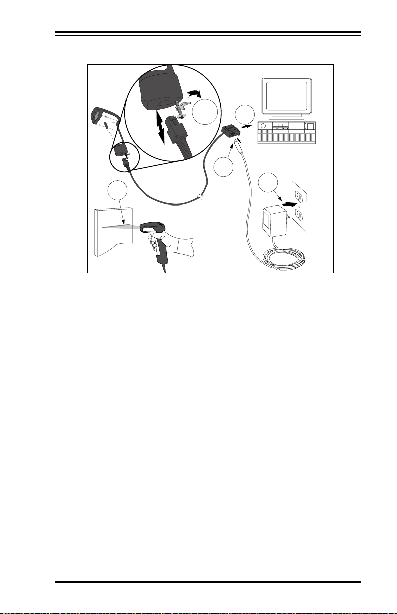
Figure 1. Installing the Scanner
1
5
2
3
4
User’s Guide
5
Page 8

How to Scan
Figure 2 illus trates some tips to help get the best scanning results:
1. The scanner must be pointed at a slight angle to the bar code.
Do not hold the scanner perpendicular to the bar code.
2. The laser beam must cross the entire bar code. The scanner
cannot correctly read if the entire bar code is not scanned.
Figure 2. Scanning Tips
1
2
1
2
6
PowerScan™
Scanner
Page 9

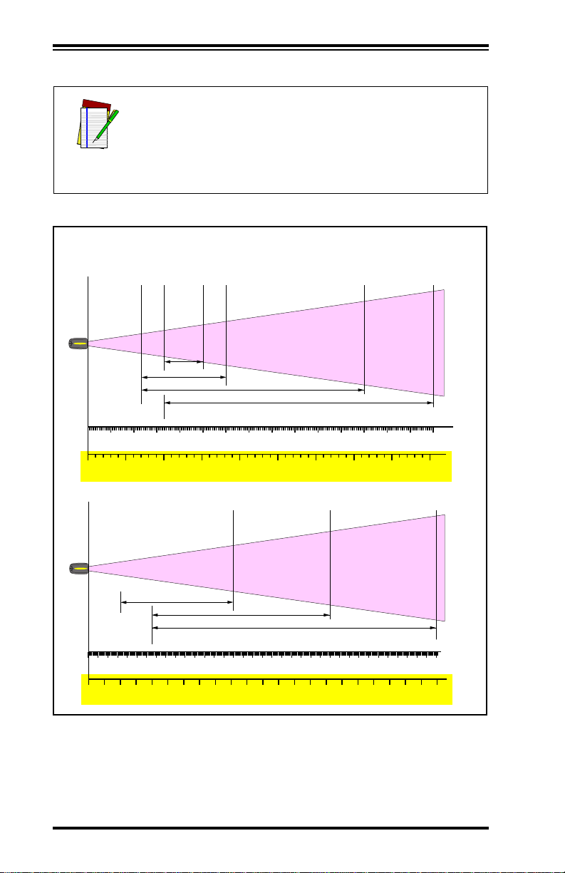
Scanning Range
There are currently four different model types for this scanner.
Depending upon the model type of your scanner, you’ll need to hold
the unit at a given distance from the bar code to achieve optimum
scanning results. The following diagrams provide range of fi eld information for each of the models when scanning grade A, Code 39 bar
codes: Standard Range (SR), High Density (HD), Long Range (LR)
and Extra Long Range (XLR).
In the context of the illustration below , a "mil" represents the minimum bar code element width. Measurements are based on SR models set with the
standard 28° scan width (as opposed to the Half
Angle setting of 14°). Reference the PowerScan Pro-
NOTE
gramming Manual for more information about the
Half Angle feature.
Specifications are subject to change without notice.
Figure 3. Depth of Field (SR)
Depth of Field
Paper Labels (SR decoded model, Code 39)
5 mil
7.5 mil
10 mil
FRONT OF SCANNER
0
15 mil
20 mil
40 mil
12345
10
20 30 40 50 60 70 80 90 100 110 120 130 140 150 160 170
55 mil
FEET
CENTIMETERS
User’s Guide
7
Page 10

In the context of the illustration belo w , a "mil" represents the minimum bar code element width. Measurements are based on HD models set with the
standard 28° scan width (as opposed to the Half
Angle setting of 14°). Reference the PowerScan Pro-
NOTE
gramming Manual for more information about the
Half Angle feature.
Specifications are subject to change without notice.
Figure 4. Depth of Field (HD)
Depth of Field
Paper Labels (HD decoded model, Code 39)
3 mil
4 mil
FRONT OF SCANNER
5 mil
7.5 mil
10 mil
20 mil
12345678
0
8
5
INCHES
10 15 20
CENTIMETERS
PowerScan™
Scanner
Page 11

In the context of the illustration below , a "mil" represents the minimum bar code element width. Measurements are based on LR models set with the a
14° scan width (as opposed to the alternate Full
Angle setting of 28°). Reference the PowerScan Pro-
NOTE
gramming Manual for more information about the
Half Angle feature.
Specifications are subject to change without notice.
Figure 5. Depth of Field (LR)
Depth of Field
Paper Labels (LR decoded model, Code 39)
7.5 mil
10 mil
15 mil
FRONT OF SCANNER
20 mil
40 mil
55 mil
12345
0
10
20 30 40 50 60 70 80 90 100 110 120 130 140 150 160
FEET
CENTIMETERS
6789
170 180 190 200 210 220 230 240 250 260 270 280
Reflective Labels (LR decoded model, Code 39)
40 mil
FRONT OF SCANNER
102345678910 11 12 13 14 15 16 17 18 19 20 21 22
55 mil
70 mil
100 mil
FEET
CENTIMETERS
User’s Guide
6706506306105905705505305104904704504304103903703503303102902702502302101901701501301109070503010
9
Page 12
In the context of the illustration belo w , a "mil" represents the minimum bar code element width. Measurements are based on XLR models set with a 10°
scan angle width.
NOTE
Specifications are subject to change without notice.
Figure 6. Depth of Field (XLR)
Depth of Field
Paper Labels (XLR decoded model, Code 39)
15 mil
FRONT OF SCANNER
20 mil
40 mil
55 mil
12345678910 11 12 13 14 15
0
FEET
CENTIMETERS
Reflective Labels (XLR decoded model, Code 39)
FRONT OF SCANNER
2345678910 11 12 13 14 15 16 17 18 19 20 21 22 23 24 25 26 27 28 29 30 31 32 33 34 35 36
40 mil
70 mil
100 mil
FEET
CENTIMETERS
10
45040035030025020015010050
PowerScan™
1100105010009509008508007507006506005505004504003503002502001501005010
Scanner
Page 13

Active Symbologies
The active (enabled) bar code symbologies in the factory defaults are:
• Code 39 (C39)
• Code 128 (C128)
• Interleaved 2 of 5 (I 2 of 5)
Your scanner should be pre-programmed with these stan dar d factory
default settings, unless...
...it was shipped to you programmed with unique, customer con-
figuration settings.
...you or another user have made changes to scanner program-
ming.
Enhanced Scanning for Hard-to-Read Bar Codes
Decoded scanners can be programmed to decode extremely poor
quality bar codes by activating advanced Quadralogic
To select this feature, see the PowerScan™ Scanner Programming
Guide available from your dealer, or you can download the manual
from our website.
Scanner programming can also be performed using your PC and the
Configurator Express
from your dealer.
™ On-Screen Programming tool also available
™ Decoding.
User’s Guide
11
Page 14

Test Your Scanner
The bar code below (Figure 7) is provided to test your scanner’s ability to read a typical Code 39 label.
Figure 7. Code 39 Bar Code Sample
Test
Figure 8. Scanner
CLASS No.
SERIAL No.
MFG. DATE:
Complies with 21CFR 1040
ACN
and part 15 of FCC Rules.
073200496
Applicable patents are listed
on label inside unit.
CUS
®
V
A
LISTED
NWGQ 2Z78
X
E
D
I
O
COVERED
BY ONE OR MORE OF THE
FOLLOWING PATENTS:
LASER RADIATION-DO NOT STARE INTO BEAM
1mw - 650-685nm CLASS 2 LASER PRODUCT
Based on 100 sec., EN60825-1/A11:1996
O
I
T
N
A
I
I
S
D
A
E
R
M
I
R
E
S
A
L
—
E
R
U
S
O
P
4,387,297 • 4,409,470 • 4,460,120
4,593,186 • 4,652,750 • 4,673,805
4,736,095 • 4,816,660 • 4,845,350
4,861,972 • 4,866,257 • 4,879,456
5,179,270 • 5,180,904 • 5,237,161
5,247,161 • 5,247,162 • 5,258,604
5,260,554 • 5,298,728 • 5,311,000
5,330,370 • 5,468,949 • 5,475,206
5,481,098
CAUTION—LASER RADIATION WHEN OPEN. AVOID EXPOSURE TO BEAM.
Labeling
T
T
E
D
F
R
O
M
T
H
I
S
D
E
V
I
C
E
.
Other patents pending
12
NOTE
Figure 8 above shows label placement ONLY. For
actual regulatory, patent and other applicable information, view the labels on the product itself, or call
your nearest sales or service representative.
PowerScan™
Scanner
Page 15

Laser Cautions
The PowerScan bar code scanner is certified in the U.S. to conform to
the requirements of DHHS/CDRH 21CFR Subchapter J for Class II laser
products (SR and LR) and Class IIIa (XLR). Class II and IIIa products
are not considered to be hazardous. The scanner contains a Visible
Laser Diode (VLD) at a wavelength of 650-670 nanometers and is
designed so that there can be no human access to harmful levels of
laser light during normal operation, user maintenance, or during prescribed service operations.
If the scan pattern is a single dot when depressing
the trigger, discontinue operation and return the
unit to the factory. Exception: When using Marker
CAUTION
CAUTION
Beam Mode a single aiming dot is projected
momentarily.
Do not attempt to open or otherwise service any
components in the optics cavity. Opening or servicing any part of the optics cavity by unauthorized
personnel may violate laser safety regulations.
Radio Frequency Interference
This devic e comp lie s w ith Par t 1 5 o f the FC C Rule s. Oper at ion is s ub ject to the following two conditions:
1. This device may not cause harmful interference, and
2. This device must accept any interference received, including
interference that may cause undesired operation.
This Class A digital apparatus complies with Canadian ICES-003.
Cet appareil numérique de la classe A est conforme à la norme NMB-
003 du Canada.
User’s Guide
13
Page 16

Troubleshooting
You can isolate problems with your scanning system by performing
these checks (refer to Figure 9):
1. If your scanner’s cable is designed to receive Power Off the
T erminal (P.O.T.), it will not operate unless it is connected to a
working host terminal that is powered on.
2. Ensure that the interface cable is securely attached to the
host. Consult your technical support manager or refer to
your host system manual to identify the proper connection
for the scanner.
3. If an external power supply is used, verify that it is securely
connected to the interface cable and AC outlet. Also ensure
that the power supply is the correct voltage rating for your
area.
4. Check to see that the interface cable is securely connected at
the scanner handle. Push the connector in to assure that it is
firmly seated. Use a Phillips head screwdriver to ensure that
the screw at the bottom of the scanner is fully tightened (but
do not overtighten).
5. If, after checking all connections, the scanner still fails to
function properly, exchange the power supply with a known
good power supply.
6. Ensure that the scanner's interface type is compatible with
the host terminal by consulting yo ur POS system manual
and/or the PowerScan Scanner Programming Guide.
7. Verify that the bar codes you are scanning are of satisfactory
quality. Bar code label verifiers are available from your
dealer if you need precise reporting of bar code details. Bar
codes that are damaged (wrinkled, smudged, or torn) may
cause the scanner to read poorly or not at all. If bar code
quality seems to be the problem, check to see if the scanner
will read a known good bar code (see Figure 7). Y ou may also
want to modify the programmable setting for advanced
Quadralogic
titled, Enhanced Scanning for Hard-to-Read Bar Codes).
14
™ decoding (see the section in this manual
PowerScan™
Scanner
Page 17

Figure 9. Troubleshooting the Scanner
7
ON
1
OFF
Programming
Kit
5
531 75790
99
6
5
ON
OFF
4
2
3
User’s Guide
15
Page 18

NOTES
16
PowerScan™
Scanner
Page 19

DECLARATION OF CONFORMITY
PSC hereby declares that the Equipment specifie d below has
been tested and found compliant to the following Directives
and Standards:
Directives: EMC 89/336/EEC
Low Voltage 73/23/EEC
Standards: EN55022-B EN60825
EN50082-1 EN60950
Equipment
Type: Bar Code Scanning Equipment
Product:
Charles W. Vanlue
Director, Corporate Quality
PSC, Inc.
959 Terry Street
Eugene, OR 97402
U.S.A.
PowerScan
PowerScan
PowerScan
™ Bar Code Scanner
™ LR Bar Code Scanner
™ XLR Bar Code Scanner
Nigel Davis
Vice President
Europe, Middle East & Africa
PSC Bar Code Ltd.
Axis 3, Rhodes Way
Watford, England
WD24YW
UK
Page 20

Asia Pacific
PSC Hong Kong
Hong Kong
Telephone: [852]-2-584-6210
Fax: [852]-2-521-0291
Italy
PSC S.R.L.
Vimercate (MI), Italy
Telephone: [39] (0) 39/62903.1
Fax: [39] (0) 39/685496
Australia
PSC Asia Pacific Pty Ltd.
North Ryde, Australia
Telephone: [61] 0 (2) 9878 8999
Fax: [61] 0 (2) 9878 8688
France
PSC S.A.R.L.
LES ULIS Cedex, France
Telephone: [33].01.64.86.71.00
Fax: [33].01.64 46.72.44
Germany
PSC GmbH
Darmstadt, Germany
Telephone: 49 (0) 61 51/93 58-0
Fax: 49 (0) 61 51/93 58 58
Corporate Headquarters
PSC Inc.
Portland, OR
Telephone: (503) 534-3553
Fax: (503) 534-3555
www.pscnet.com
Printed on recycled paper
Japan
PSC Japan K.K.
Shinagawa-ku, Tokyo, Japan
Telephone: 81 (0)3 3491 6761
Fax: 81 (0)3 3491 6656
Latin America
PSC S.A., INC.
Miami, Florida, USA
Telephone: (305) 539-0111
Fax: (305) 539-0206
United Kingdom
PSC Bar Code Ltd.
Watford, England
Telephone: 44 (0) 1923 809500
Fax: 44 (0) 1923 809 505
PSC Inc.
959 Terry Street
Eugene, OR
Telephone: (541) 683-5700
Fax: (541) 686-1702
© 2001 PSC INC. R44-2094 (Rev. E) Printed in USA (6/01)
 Loading...