

Page 1

R44-2016 (Rev. E)
LM520 Scanner
Integration & Programming Manual
Page 2

R44-2016 i-1
Contents
The LM520 Bar Code Scanner
Overview .........................................................................................................................................................1
Unpacking the LM520................................................................................................................................ .... . 2
Scanner Care .................................................................................................................................................2
Mounting the LM520
General Considerations ..................................................................................................................................3
Mounting .........................................................................................................................................................3
Mounting the Scanner Stand-Alone............ ..... ..................................... ..... ..... ................................. ..... .... ..... . 4
Integrating the Scanner to Read at the Proper Distance ................................................................................4
Integrating the Scanner Behind a Window .....................................................................................................5
Electrical Interface ..........................................................................................................................................8
Interface Cable Schematic................................................................................................................. ..... . 9
LM520 Scanner Configuration
Configuration Management ..........................................................................................................................10
Programming Methods......................................................................... ..... ..... .............................................. 12
Programming through the Serial Interface .............................................................................................12
Programming with Bar Codes................................................................................................................ 13
Conventions ..................................................................................................................................................13
Setting Serial Communication Parameters................................................................................................... 14
Baud Rate ..............................................................................................................................................14
Data Format........................................................................................................................................... 15
Flow Control........................................................................................................................................... 16
Controlling Scanning Through Host Commands.......................................................................................... 17
Triggering Scanning Using Software Switch ..........................................................................................17
Triggering Scanning Using Hardware Switch ........................................................................................ 18
Continuous Scanning Mode ...................................................................................................................18
LaserSense Scanning Mode.................................................................................................................. 19
Canceling Software Triggered Scanning ...............................................................................................19
Setting Symbology Parameters.................................................................................................................... 20
Enabling All Symbologies ......................................................................................................................20
EAN ........................................................................................................................................................21
UPC .......................................................................................................................................................21
Code 128................................... ..... ..... ..... ..................................... ..... ..... ..... ......................................... 22
Code ISBT 128.................................... ..... .... ..... ...................................... ..... .... ..... ................................ 23
Code 93..................................... ..... ..... ..... ..................................... ..... ..... ..... ......................................... 25
Codabar .................................................................................................................................................25
Code 39 ......................................... ..... ..... ..................................... ..... ..... ..... ..........................................26
Interleaved 2 of 5................................................................................................................................... 27
Standard 2 of 5...................................................................................................................................... 28
Formatting Bar Code Data............................................................................................................................ 29
Preamble ................................................................................................................................................29
Postamble ..............................................................................................................................................29
Filters..................................................................................................................................................... 30
Field Descriptions ............................................................................................................................31
Pad Character ................ ...................................... .... ..... ..... ...................................... .... ...................33
Edit Function ...................................................................................................................................33
Page 3

R44-2016 i-2
Setting the Bar Code Format................................................................................................................. 34
Additional Commands........................... ..... ..... .... ...................................... ..... ..... .... ..................................... 35
Good Read Beeper Duration .................................................................................................................35
Laser Timeout ........................................................................................................................................35
Double Read Timeout............................................................................................................................ 36
Read Verification ...................................... .... ..... ...................................... ..... .... ..... .................................36
No Read Message................. .... ..... ...................................... ..... .... ..... ................................................... 37
No Read Output Signal ..........................................................................................................................37
No Read Output Signal Mode 1 ......................................................................................................37
No Read Output Signal Mode 2 ......................................................................................................37
Diagnostic Commands ...........................................................................................................................38
Good Read LED Duration ......................................................................................................................38
Appendix A:Technical Specifications ......................................................... ..................................................A-1
Appendix B: Mechanical Specifications .......................................................................................................B-1
Appendix C: Factory Default Configuration .................................................................................................C-1
Appendix D: LM520 Programming Labels ....................................................................................................D-1
Appendix E: ASCII Conversion Table ...........................................................................................................E-1
Page 4

R44-2016 i-3
List of Tables
Table 1. Electrical Interface Specifications ..........................................................................................8
Table 2. Configuration Commands .....................................................................................................10
Table 3. Baud Rate ..............................................................................................................................14
Table 4. Data Format ..........................................................................................................................15
Table 5. Flow Control .........................................................................................................................16
Table 6. Software Switch Control .......................................................................................................17
Table 7. Hardware Switch Control .....................................................................................................18
Table 8. Continuous Scanning Mode ..................................................................................................18
Table 9. LaserSense Mode ..................................................................................................................19
Table 10. Symbologies .......................................................................................................................20
Table 11. EAN ....................................................................................................................................21
Table 12. UPC .....................................................................................................................................21
Table 13. Code 128 .............................................................................................................................22
Table 14. ISBT Symbology ................................................................................................................23
Table 15. Concatenation Pairs ............................................................................................................24
Table 16. ISBT Commands ................................................................................................................24
Table 17. Code 93 ...............................................................................................................................25
Table 18. Codabar ...............................................................................................................................25
Table 19. Code 39 ...............................................................................................................................26
Table 20. Interleaved 2 of 5 ................................................................................................................27
Table 21. Standard 2 of 5 ....................................................................................................................28
Table 22. Preamble .............................................................................................................................29
Table 23. Postamble ............................................................................................................................29
Table 24. Filter Examples ...................................................................................................................30
Table 25. Symbology Identifiers ........................................................................................................32
Table 26. Pad Characters ....................................................................................................................33
Table 27. Edit Functions .....................................................................................................................33
Table 28. Bar Code Format .................................................................................................................34
Table 29. Beeper Duration ..................................................................................................................35
Table 30. Laser Timeouts ...................................................................................................................35
Table 31. Double Read Timeout .........................................................................................................36
Table 32. Read Verification ................................................................................................................36
Table 33. No Read Message ...............................................................................................................37
Table 34. No Read Output Mode ........................................................................................................38
Table 35. Diagnostic Commands ........................................................................................................38
Table 36. Good Read LED Duration ..................................................................................................38
Table A-1. Performance Specifications ...........................................................................................A-1
Table A-2. Power Requirements ...................................................................................................... A-2
Table A-3. Physical and Environmental Specifications .................................................................. A-2
Table A-4. Agency Approvals ......................................................................................................... A-2
Table C-1. Factory Default Configuration ........................................................................................C-1
Table D-1. Programming Labels .................................................................................................... D-1
Table E-1. ASCII Conversion Table .................................................................................................E-1
Page 5

R44-2016 1
Section 1
The LM520 Bar Code Scanner
Overview
The LM520 scanner is a compact, decoded, single-line scanner for fixed position or embedded applications, such as conveyor, library, document tracking, chemical analyzers, vending
machines, point-of-sale (POS) terminals, and other attended or unattended scanning applications. The LM520 is a complete scanning system, ready to plug in and scan. The LM520
presents a fast, easy and low-cost way to incorporate scanning into any application where
you need to read a bar code.
A typical system using the LM520 scanner consists of the scanner itself and a host system
such as a PC, POS system, or package sorting system. The host system controls the scanner
and receives the decoded bar code data produced by the scanner. The laser in the LM520
scanner emits coherent visible light. When a bar code passes through the scanner’s beam,
light is reflected off the bar code. The scanner collects this reflected light, processes it into a
digital signal and decodes it into data that can be used by the host system. In some cases the
data may be processed further by the scanner before being transmitted to the host.
The LM520 has four different operational modes which can be used to scan a bar code. The
four operational modes include:
• an external switch such as an output line from a Programmable Controller (also
known as a PLC) can be used to enable scanning
• software commands from the host system
• continuous scanning operations, and
• a unique PSC motion detection circuitry called LaserSense™. This circuitry allows
the LM520 to only scan when an object is passed in front of it.
The various modes are selected via host commands or special programming bar codes.
Page 6

The LM520 Bar Code Scanner Section 1
2 LM520 Scanner Integration & Programming Manual
Unpacking the LM520
The LM520 bar code scan scanner is shipped in custom packaging. Carefully open the
package, and remove the scanner from the packing material.
The LM520 standard configuration includes:
• LM520 scanner
• power supply
• mounting hardware (two bolt studs with nuts)
• interface cable - male DB9 (scanner side) [with optional beeper if ordered]
• diskette with this manual and other information
When you open the shipping cart on, visually inspect the pack age’s contents. If any parts ar e
damaged or you need additional hardware, please contact your reseller or the PSC
Customer Support Center at 1-800-547-2507.
Scanner Care
The LM520 bar code scanner contains sensitive components which require special
handling. PSC Inc. may not warrant damage due to improper handling.
• Do not open the scanner’s case. Doing so will void the warranty.
• Avoid touching the front window. Fingerprints will degrade the scanner’s
performance.
• Only clean the scan window when visual inspection reveals dirt or residue.
Remove lint or foreign material be present with filtered clean air. Remove
fingerprints or other residue using clean, cotton-tipped applicators dipped in
isopropyl alcohol, or with soft tissues dipped in high-quality lens or eyeglass
cleaner. Do not reuse cotton-tipped applicators or tissues.
• Do not scrub the window.
• Never wipe the window with a dry tissue or applicator.
Page 7

R44-2016 3
Section 2
Mounting the LM520
The LM520 bar code scanner is designed to be mounted to a stand in a fixed position. This
section describes the layout of the mounts for optimum scanner performance.
General Considerations
Although the LM520 bar code scanner has been designed to be impact-resistant, it is important to consider the effect of the environment on the scanner. In particular, the mounting
scheme should minimize the possibility of foreign objects contacting the window’s surface.
Such contact will damage the window over time and re duce the scann er’s performance. The
mounting design should also take into consideration the clearance needed for the power
supply and interface cables. These cables should be routed away from the operator’s working area in attended applications.
Mounting
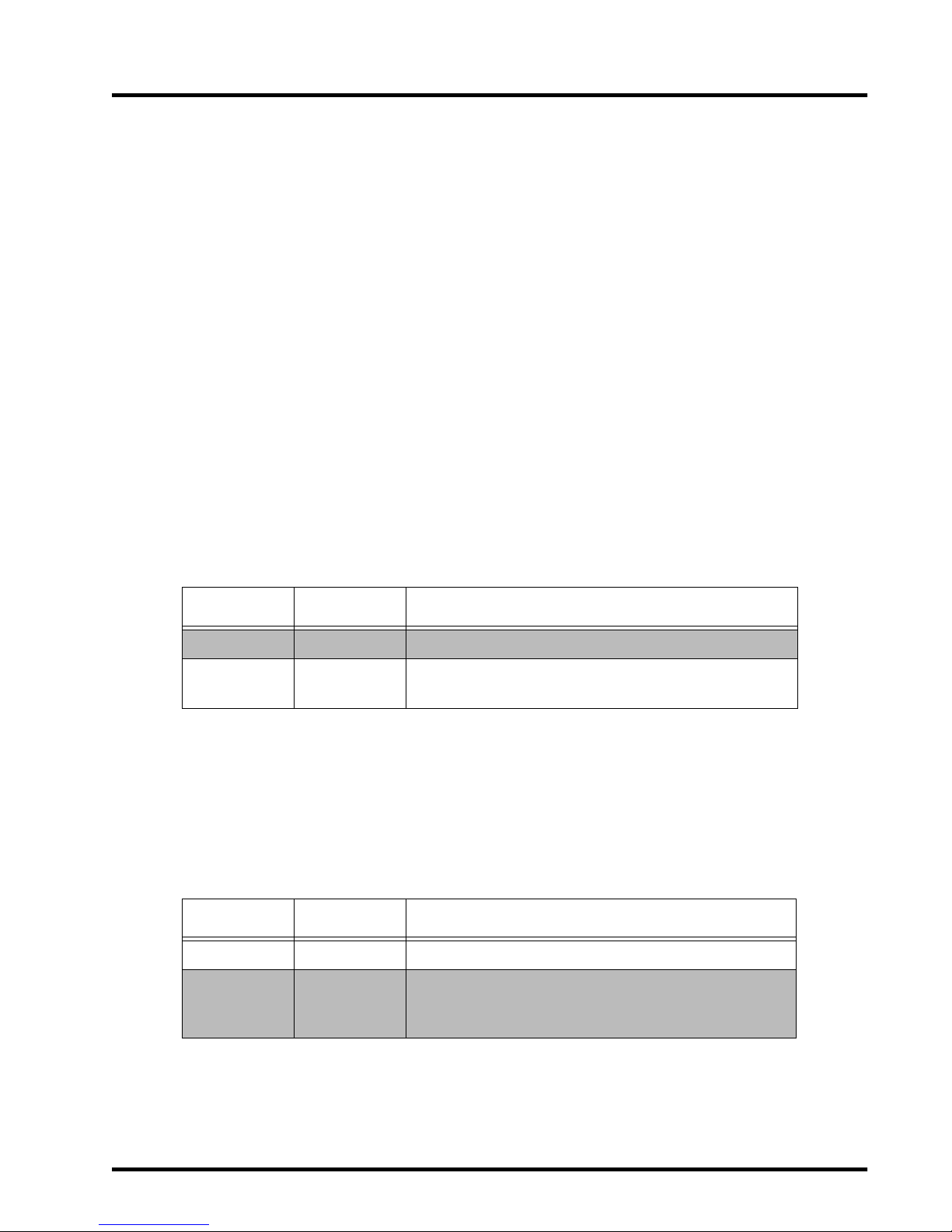
System integration is made easy with the LM520’s unique mounting design. Six mounting
grooves in the scanner’s sealed enclosure enable mounting on any one of four sides. When
looking at the back of the scanner, these slots are located as shown in Figure 1.
Figure 1. Mounting
Appendix B, Mechanical Specifications shows mechanical drawings of the precise position of
the mounting slots relative to the scanning laser beam.
6789
12345
Mounting Slots
Mounting Slots
1.00"
(2.54cm)
0.50"
(1.27cm)
0.50"
(1.27cm)
0.675"
(1.71cm)
0.675"
(1.71cm)
LM520 Scanner
Mounting Slots (6 total)
Page 8

Mounting the LM520 Section 2
4 LM520 Scanner Integration & Programming Manual
Mounting the Scanner Stand-Alone
For most instances using an adjustable mount is recommended. The position of the scan line
can be fine-tuned during actual installation and the scanner’s distance from the scanned
object can be easily changed. The location of the operator should also be considered for
attended applications. Care should be taken to position the scanner to minimize the possibility of the operator overturning the scanner, spilling liquid on the scanner, inadvertently
unplugging the cables, and so on.
Integrating the Scanner to Read at the Proper Distance
When deciding how to mount the LM520, there are many criteria that must be considered.
First, there are minimum and maximum distances that the bar code can be from the front of
the scanner to properly read, depending on the size of the bar code. These distances, or
depth of field, are specified in Appendix A, Technical Specifications.
Second, the scanner must be positioned so that the bar code to be read is not “square” or
parallel to the front of the scanner. The scanner must have at least 3 degrees skew angle to
operate properly. See Appendix B, Mechanical Specifications for such information as skew,
pitch, and the scanner’s mechanical parameters.
Third, the scanner must be positioned so that the scan line will be long enough to cover the
entire bar code. The scan line should exceed the width of the bar code since only about 80%
of the scan line is usable (see Figure 2). Use the following formula to calculate the expected
usable line length (l) at a given distance (d):
l = [(d+0.88in) x 2 x tan (q)] x 0.8 (if d is measured in inches)
or
l = [(d+2.34cm) x 2 x tan (q)] x 0.8 (if d is measured in centimeters)
where
l = usable line length
d = distance from the front of scanner
q = half of the scan angle, (23° ± 2.0°)
Page 9

Section 2 Mounting the LM520
R44-2016 5
Figure 2. Mounting the Scanner
Integrating the Scanner Behind a Window
When the LM520 scanner is integrated into a larger system, additional factors must be taken
into account. The most important of these is an additional window placed between the
LM520 and the bar code to be read. While an additional window provides protection for the
LM520, it will also degrade the scanner’s performance due to the need for the laser light to
traverse two additional optical surfaces passing through to the bar codes, and the reflected
light returning. Following the instructions in this section will help optimize the amount of
outgoing light that reaches the bar code and the amount of reflected light that is collected by
the scanner.
The LM520 scanner emits a laser beam in the form of a scan line. The beam’s light exits the
scanner’s window and reflects off the bar code symbol. The reflected light returns through
the window, and is collected with a photodiode. As in any optical system, any type of window causes a reduction in the amount of light that exits or enters the scanner since some of
the laser light is lost due to surface reflection.
LM520 scanner
l = 80%
of scan line
d
.88"
2.34cm
q=
Page 10

Mounting the LM520 Section 2
6 LM520 Scanner Integration & Programming Manual
The design and placement of the window is critical for optimum system performance. The
following issues must be considered.
• The window must not block outgoing laser light.
• The window must not block laser light reflected from the bar code.
Figure 2 shows the minimum size and position of the window along the horizontal and vertical axes, respectively. The minimum window size must increase as
the distance between the scanner and the window increases. This is necessary
to accommodate the width of the scan line.
• Reflections of outgoing laser light caused by the window or other reflective surfaces should not reach the front window of the scanner.
Determine the window tilt based on your application. The tilt angle of the window (that is,
its position relative to the optical axis or center-line) is important because a portion of the
emitted light will always be specularly reflected from each of the two window surfaces. This
reflected light must not reach the scanner’s window either directly or via multiple reflections from other parts of the system.
Figure 3. Tilt Angle
Nominal
Beam Path
d = 1.250"
31.74mm
0.880"
22.34mm
Angle = 103.7˚
0.125"
3.18mm
0.820"
20.83mm
Reflected light
Window
Angle
= 90 + 0.5 [ arctan (
)]
= 103.7
0.65
1.25
Page 11

Section 2 Mounting the LM520
R44-2016 7
An example of acceptable system window inclination is shown in Figure 2. As can be seen,
moving the system wind ow cl oser to the scanne r mak es it n eces sary to incr e ase the win dow
angle with respect to vertical. Less inclination is necessary if the reflection is directed below,
rather than above the scanner, since laser light is emitted near the bottom of the scanner’s
window and collected near the top of the scanner’s window. If the light reflected from the
window will be deflected above the scanner , the required window angle (fr om horizontal) is
given by:
If the light will be deflected below the scanner , the r equired window angle (from horizontal)
is given by:
The window material you select depends on the anticipated environment and your
scanner’s intended use. Appropriate window materials include glass, sapphire, and plastic.
Glass, and especially sapphire, have adequate surface hardness for most applications.
However , if you use any type of plastic, it should have a protective hard-coat on the exposed
surface. The hard-coat will protect the plastic surface from damage if the system window
needs to be cleaned.
In addition to hard-coating, some window applications may require special treatment such
as antistatic or antireflection coatings. In general, do not use antiglare coatings due to
undesirable polarization and diffusion effects.
Angle
= 90 + 0.5 [ arctan (
)]
if d is measured in inches
0.65
d
Angle
= 90 + 0.5 [ arctan (
)]
if d is measured in cm
1.65
d
Angle
= 90 - 0.5 [ arctan (
)]
if d is measured in inches
0.2
d
Angle
= 90 - 0.5 [ arctan (
)]
if d is measured in cm
0.51
d
Page 12

Mounting the LM520 Section 2
8 LM520 Scanner Integration & Programming Manual
Electrical Interface
The LM520 scanner communicates with the host over a standard DB-9 connector. The
pinouts for the connector are shown in Table 1.
Table 1. Electrical Interface Specifications
Pin #
Direction
(relative to
LM520)
Signal Function
1 Output
Beeper/
Good Read
1
1
Beeper Drive/Good Read source current must be limited to 50mA with a maximum voltage of 5VDC.
5VDC output signal used to drive an audio indicator.
2 Output TX
Serial asynchronous RS232C le vel data transm itted to the host . NRZ f ormat
and user programmable f or wo rd fo rmat and baud rate. (Default: 9600 baud,
8 data bits, no parity, 1 stop bit).
3 Input RX
Serial asynchronous RS232C level data r eceived f r om th e ho st. NRZ format
and user programmable f or wo rd fo rmat and baud rate. (Default: 9600 baud,
8 data bits, no parity, 1 stop bit).
4 Output
No Read
2
2
No Read output will source 15mA @ 5VDC. The maximum sink current must be limited to 200mA with a maximum voltage of 14VDC.
This signal is asserted at the end of a scanning cycle if no label is decoded
and will remain asserted until:
1. A successful decode occurs, or
2. A user specified timeout period elapses.
This may be configured in 100ms increments from 100 ms to 9900 ms
(9.9 seconds). Refer to the section titled No Read Output.
NOTE: If the timeout is used, the signal will be immediately deasserted if a
software scan command, hardware scan trigger on pin 9 or a LaserSense
scan occurs before the user specified tim e elapses. Setting a timeout is not
available in Continuous Scan mode.
5 Input Gnd Power supply/signal ground.
6 Input Vcc Power supply input voltage (4.75 - 12.0VDC)
7 Input CTS RS232C Clear to send control line.
8 Output RTS RS232C Request to send control line.
9 Input
Scan Trigger
3
3
Scan trigger signal must be limited to a maximum input voltage of 5VDC with a maximum input current of 10mA.
Ground on this input initiates bar code scanning. Scanning will continue
until either: (a) this line returns to high (5VDC) level, or (b) this line is disconnected, or (c) the programmed time period expires, or (d) a bar code is
decoded.
Page 13

Section 2 Mounting the LM520
R44-2016 9
Interface Cable Schematic
The drawing in Figure 4 shows a schematic view of the electrical connection between the
scanner and the host.
Figure 4. Interface Cable Schematic
ORANGE
YELLOW
VIOLET
GREEN
RED
WHITE
BROWN
BLUE
1
2
3
4
5
6
7
8
9
3
2
7
4
5
1
2
3
DB25-S
DB9-P
HOST END
SCANNER END
Connector is a 2.5 mm stereo plug
for the scan trigger, no read signal
and power supply ground.
Power Supply
4.75 - 12VDC
Beeper
(if applicable)
BEEPER/GOOD READ
TXD
RXD
NO READ
GND
VCC IN
CTS
RTS
TRIGGER_IN
Page 14

R44-2016 10
Section 3
LM520 Scanner Configuration
The LM520 offers a command interface which allows a wide range of customization. Commands can be combined with standard programming bar codes to develop an active configuration and a saved or factory default configuration.
Configuration Management
The LM520 scanner always contains two configuration sets: the Active configuration and
the Factory Default configuration. Both configurations are stored in nonvolatile memory.
When the scanner receives a command changing the configuration, it changes the Active
configuration. If the scanner is reset to the Factory Default configuration, the factory
defaults are copied to the Active configuration. See Appendix C, Factory Default Configura-
tion for a concise list of the factory defaults.
The LM520 offers the ability to change and save a new Factory Default configuration. To
overwrite the Factory Default configuration as shipped from PSC, first make changes to the
Active Configuration, then store the Active Configuration as the Factory Default. The
previous Factory Default will be overwritten. Figure 5 illustrates this process. Table 2
describes the commands for changing the default configuration.
Table 2. Configuration Commands
Command Setting
Z1
Reset active configuration to factory defaults.
The active configuration will be overwritten.
Z2
Store the active configuration as Factory Default.
The contents of the Factory Default will be overwritten.
Page 15

Section 3 LM520 Scanner Configuration
R44-2016 11
Figure 5. Configuration Management
Factory Default
Configuration
Host Serial Command
or
Programming Label
Active
Configuration
Z2
Z1
Z1 - Copy vaulted configuration into active configuration.
Z2 - Copy configuration from active configuration to the factory default configuration.
Page 16

LM520 Scanner Configuration Section 3
12 LM520 Scanner Integration & Programming Manual
Programming Methods
The LM520 scanner may be programmed either by sending commands from a host over the
serial interface or by the using bar codes containing programmable commands. Typically,
the scanner is programmed over the serial interface when it is integrated into a system.
Appendix D, LM520 Programming Labels, contains a minimal set of programming
bar codes and the section titled, Programming with Bar Codes, on page13, describes how to
create programming bar codes.
Programming through the Serial Interface
The easiest and most common way to program the LM520 is by sending ASCII commands
through the serial interface. Each command transmission must begin with the STX (0x02
hex) and ESC (0x1B hex) characters. Next, the command itself is transmitted, followed by
any necessary parameters. The command transmission ends with an ETX (0x03 hex).
A complete serial command transmission, therefore, consists of:
STX-ESC-[command]-[parameters]-ETX
The scanner uses an ACK/NAK protocol to communicate with the host. The scanner does
not echo received data back to the host, and will not acknowledge transmissions which do
not begin with STX-ESC and end with ETX. Upon receipt of a valid command sequence,
the scanner responds in one of two ways:
• All commands that are valid (both commands and parameters) take the requested
action and then transmit an ACK to the host.
• If the command is invalid, the scanner responds with an ASCII NAK (0x15 hex).
All valid commands return an ACK. Otherwise, a NAK is returned if the command is not
valid. If the command is not formatted properly (missing the STX, ESC, or ETX), the scanner
does not respond. Each command recognized by the scanner consists of two ASCII characters, followed by any required parameters.
Page 17

Section 3 LM520 Scanner Configuration
R44-2016 13
Programming with Bar Codes
The LM520 scanner can also be programmed by scanning bar codes which contain commands. This method allows users to easily adjust scanner parameters.
Bar codes used for programming must be Code 128, with a Function Code 3 (FNC3) as the
first character. The command following the FNC3 character configures the scanner in
exactly the same way as if it had received the command over the serial line, except that the
scanner will not acknowledge the command on the serial line. Each bar code may contain
only one command. All parameters for the command must be included in the label with the
command characters. For example, the label to limit the minimum number of Code 39 to 5
characters would be.
<FNC3>OH05
The scanner can be programmed not to accept programming bar codes by using the Disable
Programming Bar Codes command (@Y). If you disable the programming with bar codes
feature, the scanner will still accept programming commands through the serial port. The
Enable Programming (@Z) bar code commands will always be accepted by the scanner, and
cannot be disabled.
If Disable Programming Bar Codes (@Y) is set, all programming bar codes except Enable
Programming Bar Codes (@Z) will be treated as standard Code 128 bar codes.
Conventions
The remainder of this manual presents the valid commands in a tabular format. These tables
contain two or three columns.
• First column
– Bar Code Command, contains the two-letter ASCII string which
the scanner accepts as programming commands through the serial port or in a
programming label. See Appendix D, LM520 Programming Labels, for instructions
on how to create bar code programming labels.
• Second co lumn
– Bar Code Parameters, may be present. If an entry appears in this
column, a parameter setting is required to complete the command.
• Last column
– Setting, describes the effect of the command and its associated
parameters.
• Default Entries – The factory default settings for the scanner are shaded and
denoted by asterisk.
A concise list of these defaults is presented in Appendix C, Factory Default Configuration.
³OH05
Page 18

LM520 Scanner Configuration Section 3
14 LM520 Scanner Integration & Programming Manual
Setting Serial Communication Parameters
The first step in the integration process is establishing communications between the scanner
and the host. This is done by matching the scanner’s communications parameters to the
serial communication requirements of the host. The Baud Rate, Data Format and Flow
Control communication settings of the scanner must match the serial communications
requirements of the host. For example, if the scanner is sending data at the wr ong baud rate,
the host will not be able to interpret the data that is being sent. The following section outlines the RS-232 communication settings.
Baud Rate
Use one of the commands shown in Table 3 to set the LM520 baud rate. Note that the scanner and the host must communicate at the same rate for communication to be successful. An
ACK command will be sent by the scanner at the new baud rate, indicating that the command has been received and understood.
* Asterisk and shading denotes the Factory Default Setting.
Table 3. Baud Rate
Command Setting
DA Baud = 300
DB Baud = 600
DC Baud = 1200
DD Baud = 2400
DE Baud = 4800
DF * Baud = 9600
DG Baud = 19200
DH Baud = 38400
Page 19

Section 3 LM520 Scanner Configuration
R44-2016 15
Data Format
These parameters control the data format in which the LM520 will communicate with the
host. Note that the scanner and host must
communicate in the same format for communication to be successful. An ACK command will be sent by the scanner in the new format indicating that the command has been received and understood. Table 4 lists the commands for
the data format options.
Table 4. Data Format
Command Setting
EC 7 data bits, 1 stop bit, even parity
ED 7 data bits, 1 stop bit, odd parity
EK 8 data bits, 1 stop bit, even parity
EL 8 data bits, 1 stop bit, odd parity
EM * 8 data bits, 1 stop bit, no parity
EN 8 data bits, 2 stop bits, no parity
Page 20

LM520 Scanner Configuration Section 3
16 LM520 Scanner Integration & Programming Manual
Flow Control
As shown in T able 5, the LM520 scanner supports standard flow contr ol protocols, including
XOn/XOff (software flow control) and CTS/RTS (hardware flow control). If CTS/RTS is
being used, first send the HA command before sending a new Flow Control command
(HB - HN). If the CTS and RTS lines are not used for flow control, they can be used to monitor and control the scanner. The default setting is no flow control: CTS = none; RTS = low
when scanning in process and Xon/Xoff disabled. To return to this configuration send the
HA command followed by the HN command.
Table 5. Flow Control
Command Setting
HA *
No Flow Control
Xon/Xoff disabled
CTS mode = none
RTS mode = RTS low when ready to receive
HB
Xon/Xoff Enabled
CTS mode = none
HC
CTS mode = Low to transmit
Xon/Xoff disabled
HD
CTS mode = High to transmit
Xon/Xoff disabled
HE
CTS mode = Low to begin scanning
Xon/Xoff state unchanged
HF
CTS mode = High to begin scanning
Xon/Xoff state unchanged
HG RTS = Always Low
HH RTS = Always High
HI RTS = Low when scanner is ready to receive commands
HJ RTS = High when scanner is ready to receive commands
HK RTS = High when scanner has data to send
HL RTS = Low when scanner has data to send
HM RTS = High when scanning is in progress
HN * RTS = Low when scanning is in progress
NOTE
If Xon/Xoff is enabled, then RTS = low when scanning and CTS = none
If Xon/Xoff is disabled, then RTS = low when ready to scan and CTS = none
Low = Mark signal (negative voltage)
High = Space signal (positive voltage)
Page 21

Section 3 LM520 Scanner Configuration
R44-2016 17
Controlling Scanning Through Host Commands
Triggering Scanning Using Software Switch
A host can instruct the scanner to begin scanning by sending the Scan Now command.
Table 6 shows that the number of scanning passes is user programmable.
Except for terminating after the requested number of scans if no bar code is read, scanning
initiated through this command performs identically to scanning initiated by pressing the
trigger (assertion on the Scan Trigger line, pin 9).
Table 6. Software Switch Control
Command Parameter Setting
ZD XX
(01-99)
Scan Now. Begin scanning immediately. Scan until a bar
code is decoded, or for a maximum of XX scans.
NOTE: The LM520 scans approximately 42 times per second.
ZD 00
Scan Now. Begin scanning immediately. Scan until a bar
code is decoded, or until the scanning timeout expires. See
BH command in Table 30.
NOTE
The ZD command returns ACK immediately followed by the bar code data when a bar code is decoded.
Page 22

LM520 Scanner Configuration Section 3
18 LM520 Scanner Integration & Programming Manual
Triggering Scanning Using Hardware Switc h
Using a hardware switch can also be configured to respond to the CTS line rather than the
Scan Trigger line using the commands below.
Scanning initiated in response to a CTS signal performs identically to scanning initiated by
pressing the trigger (assertion on the Scan Trigger line, pin 9). To disable scanning in
response to a CTS signal, set the CTS mode to a non-scanning mode (HA, HB, HC or HD) as
described in Setting Serial Communication Parameters on page 14.
Hardware scanning continues until either the Scan T rigger is deasserted or until the scanner
timeout expires. See BH command in Table 30.
Continuous Scannin g Mode
The LM520 may also be set for Continuous Scanning mode through host commands.
Table 7. Hardware Switch Control
Command Setting
HE
CTS mode = High signal triggers scanning
(Other serial options unchanged)
HF
CTS mode = Low signal triggers scanning
(Other serial options unchanged)
Table 8. Continuous Scanning Mode
Command Parameter Setting
NC Continuous scanning on.
ND*
Continuous scanning off – only for use when programming
with bar codes. (Also, see Canceling Software Triggered
Scanning.)
Page 23

Section 3 LM520 Scanner Configuration
R44-2016 19
LaserSense Scanning Mode
LaserSense is a significant technology breakthrough. LaserSense technology has two key
advantages over other automatic triggering methods.
• It detects movement at a user configurable range from the scanner. This eliminates false triggers from movement in the general area and clearly identifies
where the bar code should be placed with a stable marker point.
• It is integral to the scanner. There are no additional components to fail or add-on
components that are not well integrated.
Using a background color that contrasts with the object being detected will enhance
performance.
Default: NG60
Range = 45 - 70
NG45 = 4.5” (minimum)
NG60 = 10” (default)
NG70 = 23” (maximum)
Canceling Software Triggered Scanning
A scan triggered by software, such as software trigger (ZD), LaserSense scanning (NA), or
continuous scanning (NC) can be canceled using the ASCII DC4 command from the host, or
by scanning the ND or NB labels. The ASCII DC4 command is a single byte (0x14 hex) and
should not be sent with a STX-ESC preceding it. When the LM520 receives this single character, it will respond with an ACK, turn active scanning off and be ready to receive additional programming commands. Sending this DC4 command is sufficient and does not
require the host to send th e Continuous Scanning O f f (ND) or Disable Lase rS ense (NB) co mmands.
Table 9. LaserSense Mode
Command Parameter Setting
NA *
Enable LaserSense. When an object is detected, scanning
occurs until the scanning timeout expires.
See the BH command in Table 30.
NB
Disable LaserSense – only for use when programming with
bar codes.(Also see Canceling Software Triggered Scanning.)
NG
XX
(45 - 70)
Set range for LaserSense. Higher values increases the
effective range.
A value that is too large will result in false triggers and
continuous scanning.
A value too low will result in no triggering.
Tolerance = ±20%
Page 24

LM520 Scanner Configuration Section 3
20 LM520 Scanner Integration & Programming Manual
Setting Symbology Parameters
The LM520 is able to decode UPC-A, UPC-E, EAN-8, EAN-13, Code 39, Code 128, Code 93,
Codabar, Interleaved 2 of 5, and Standard 2 of 5 symbologies. The decoder will actively
attempt to match bar code data against all symbologies which are enabled. Thus, performance is enhanced by disabling symbologies which are not used in a particular environment. The possibility of misreads due to symbology overlap will also decrease by disabling
unused symbologies.
Enabling All Symbologies
It is possible to enable all symbologies at once. This command is typically used for diagnostic or demonstration purposes. For best performance in actual use, only those symbologies
which are needed should be enabled.
Table 10. Symbologies
Command Setting
QM Enable all symbologies.
NOTE
This command does not enable either ISBT 128 or UPC/EAN supplementals.
Page 25

Section 3 LM520 Scanner Configuration
R44-2016 21
EAN
UPC
Table 11. EAN
Command Parameter Setting
RA Disable EAN-13
RB Enable 2 and 5 digit supplementals for EAN-13 and EAN-8.
RC * Enable EAN-13
RN Disable EAN-8
RP * Enable EAN-8
RS
Disable all EAN 2 and 5 digit supplementals
(EAN-8, EAN-13).
QY
xx
(01-99)
Enable number of scans to try to build EAN/UPC 2 and 5
digit supplementals. Maximum number of scans is 99, the
default is 15
1
1
The higher the number of tries to build the supplemental portion of the code, the longer it takes EAN/UPC labels
without supplemental code to decode.
Table 12. UPC
Command Parameter Setting
QA
Disable UPC-A (If EAN-13 = enabled, UPC-A labels will
decode as EAN-13).
QB
Enable 2 and 5 digit supplementals for UPC-A and
UPC-E
QC * Enable UPC-A
QH * Disable expansion of UPC-E to UPC-A
QI Enable expansion of UPC-E to UPC-A
QL * Enable UPC-E
QV Disable UPC-E
QX Disable all UPC 2 and 5 digit supplementals (UPC-A UPC-E)
QY
xx
(01-99)
Enable number of scans to try to build EAN/UPC 2 and 5
digit supplementals. Maximum number of scans is 99, the
default is 15
1
1
The higher the number of tries to build the supplemental portion of the code, the longer it takes EAN/UPC labels
without supplemental code to decode.
Page 26

LM520 Scanner Configuration Section 3
22 LM520 Scanner Integration & Programming Manual
Code 128
Reads variable length bar codes 1 to 50 characters.
Table 13. Code 128
Command Setting
TA Disable Code 128
TC * Enable Code 128
TD Enable function code transmission
TE * Disable function code transmission
TF Enable UCC 128 Emulation
NOTE
Code 128 function codes are transmitted as follows:
FNC1 = 80h, FNC2 = 81h, FNC3 = 82, FNC4 = 83h
FNC3 = in the first data position of a Code 128 bar code is reserved for programming labels and
no data will be transmitted to the host from a programming label.
Page 27

Section 3 LM520 Scanner Configuration
R44-2016 23
Code ISBT 128
ISBT 128 is a bar code symbology for labeling of whole blood and blood components
adopted by the International Council for Commonality in Blood Banking Automation.
(ICCBBA). Implementation of ISBT 128 requires the payment of a registration fee and an
annual license fee thereafter. Contact the ICCBBA in Durham, NC USA. Their web address
is: (http://www.ICCBBA.inter.net
)
The ISBT 128 standard allows two bar codes to be read as if they were a single bar code,
known as concatenation. The physical placement of labels that can be concatenated is done
so that a laser beam can pass completely through both labels. The information for both bar
codes is transmitted to a host computer at the same time. There are 19 different code types
in the ISBT symbology.
Table 14. ISBT Symbology
ISBT 128 Single label codes
Donation Collection Date
Donation Collection Date and Time
Manufacturer’s Identity and Container Information
Manufacture’s Lot Number
Nationally-specified Special Testing
National use
Staff Member Identification Number
Date of Production
Date and Time of Production
Donor Identification Number
Special Concatenation Programming Label
ISBT 128 Concatenation label codes
1
1
Of these, 8 types may be concatenated together in seven legal ways (see the Concatention Pairs table on following page).
Blood Groups
Data ids are ‘=‘ and ‘%’, label length is 6 data
characters including data ids.
Nationally-specified Confidential Unit Exclusion
Status.
Data ids are ‘&’ and ‘!’, variable length, nationally defined
Donation Identification Number
Data ids are ‘=‘ and x (where x is A-Z or 0-9), label length is 16
data characters including data ids.
Nationally-specified Donor Identification Number Data ids are ‘&’ and ‘;’, variable length, nationally defined
Expiration Date
Data ids are ‘=‘ and ‘>‘, label length is 8 data
characters including data ids.
Expiration Date and Time
Data ids are ‘&‘ and ‘>‘, label length is 12 data
characters including data ids.
Product Code
Data ids are ‘=‘ and ‘<‘, label length is 10 data
characters including data ids.
Nationally-specified Product Code
Data ids are ‘&’ and ‘<’, label length is, label length is 10 data
characters including data ids).
Page 28

LM520 Scanner Configuration Section 3
24 LM520 Scanner Integration & Programming Manual
The other 11 types that are not normally concatenated may be specially programmed to be
concatenated. See the specification for ISBT 128 from ICCBBA for creating specially
programmed concatenated bar codes.
Table 15. Concatenation Pairs
Normal Concatenation Pairs
Donation Identification Number & Blood Groups
Donation Identification Number & Nationally-specified Donor Identification Number
Donation Identification Number & Nationally-specified Confidential Unit
Exclusion Status
Product Code & Expiration Date
Nationally-specified Product Code & Expiration Date
Product Code & Expiration Date and Time
Nationally-specified Product Code & Expiration Date and Time
Table 16. ISBT Commands
Command Setting
TQ
Enables single label mode ISBT 128, disables concatenated label mode ISBT 128. The single label mode
will read all 19 ISBT 128 labels as single labels only (no concatenation is done).
T o read single label ISBT 128, bo th Code 128 must be enabled (TC) and single ISBT 128 mu st b e enab led
(TQ). Standard Code 128 will not read while single ISBT 128 is enabled. To disable ISBT 128, use TA
command.
TR
Enables concatenated mode ISBT 128, disables single ISBT 128. The concatenation mode will only read
the 8 types of ISBT 128 labels that are used in concatenation. See Table 14 for the 8 types of concatenation labels and Table 15 for their legal combinations with other concatenation types. The other 11 types
of ISBT labels that are not normally used in concatenation will still read as single labels. However, with
the use of a special programming label, the ot her 11 types of ISBT128 labels that ar e not norm ally concatenated may be concatenated. If they are specially programmed, they will not read as single labels. Only
one special concatenation of these other 11 type labels can be programmed at a time.
T o read concat enated ISBT 128, both Code 128 m ust be enabled (TC) an d concatenat ed ISBT 128 m ust be
enabled (TR). Standard Code 128 will not read while concatenated ISBT 128 is enabled. To disable ISBT
128, use TA command.
TS
Disables the specially programmed concatenated ISBT 128 labels, if defined. To again read specially programmed concatenated ISBT 128 labels, use TR command followed by the special programming label.
See the specification for ISBT 128 from ICCBBA for creating specially programmed concatenated
bar codes.
Page 29

Section 3 LM520 Scanner Configuration
R44-2016 25
Code 93
When Code 93 is enabled, the bar code length defaults are set to zero which allows the scanner to read Code 93 bar codes of varying lengths up to 50 characters. If the scanner will be
used for specific fixed length bar codes, use the UE and UF commands to enable these fixed
lengths.
Codabar
When Codabar is enabled, the bar code length defaults is set to zero which allows the scanner to read Codabar bar codes of varying lengths up to 50 characters. If the scanner will be
used for specific fixed length bar codes, use the VE and VF commands to enable these fixed
lengths.
Table 17. Code 93
Command Parameter Setting
UA * Disable Code 93
UB Enabled Code 93
UE
XX
(00 - 50)
Set minimum length for Code 93 to XX.
If 00 is selected, the scanner ignores the min. and max
settings.
UF
XX
(00 -50)
Set maximum length for Code 93 to XX.
Table 18. Codabar
Command Parameter Setting
VA * Disable Codabar
VB Enable Codabar
VC * Disable transmission of start/stop characters
VD Enable transmission of start/stop as upper-case characters
VE
XX
(00 - 50)
Set minimum length for Codabar to XX characters. Includes
start/stop and check characters, if transmitted.
If 00 is selected, the scanner ignores the min. and max
settings.
VF
XX
(00 - 50)
Set maximum length for Codabar to XX characters. Includes
start/stop and check characters, if transmitted.
VG Enable transmission of start/stop as lower-case characters
Page 30

LM520 Scanner Configuration Section 3
26 LM520 Scanner Integration & Programming Manual
Code 39
When Code 39 is enabled, the bar code length defaults is set to zero which allows the scanner to read Code 39 bar codes of varying lengths up to 46 characters. If the scanner will be
used for specific fixed length bar codes, use the OH and OI commands to enable these fixed
lengths.
Table 19. Code 39
Command Parameters Setting
OA Disable Code 39
OB * Enable standard Code 39
OC Enable full ASCII Code 39
OD * Disable Modulo 43 check character
OE Enable Modulo 43 check character
OF * Disable transmission of the start/stop characters
OG Enable transmission of the start/stop characters
OH
XX
(00 - 46)
Set minimum data characters to XX characters.
Includes start/stop characters and check characters, if
transmitted. If set to 00, the scanner ignores the
min/max settings.
OI
XX
(00 -46)
Set maximum data characters to XX characters.
Includes start/stop characters and check characters, if
transmitted.
OJ Enable transmission of the check character
OK * Disable transmission of the check character
Page 31

Section 3 LM520 Scanner Configuration
R44-2016 27
Interleaved 2 of 5
When Interleaved 2 of 5 is enabled, the default bar code length is fixed at 14 characters
(PD14 & PE14).
Table 20. Interleaved 2 of 5
Command Parameters Setting
PA * Disable Interleaved 2 of 5.
PB Enable Interleaved 2 of 5 without a check digit.
PC Enable Interleaved 2 of 5 with a check digit.
PD
XX
(04 - 50)
Set minimum number of data characters for Interleaved
2 of 5 to XX characters. Add check digit, if transmitted.
PE
XX
(04 - 50)
Set maximum number of data characters for Interleaved 2
of 5 to XX characters. Add check digit, if transmitted.
PO *
Disable transmission of Interleaved 2 of 5
check digit.
PP
Enable transmission of Interleaved 2 of 5
check digit.
NOTE
The total number of characters must be even. If the Check Digit is included, the number of data
characters must be odd.
Page 32

LM520 Scanner Configuration Section 3
28 LM520 Scanner Integration & Programming Manual
Standard 2 of 5
When Standard 2 of 5 is enabled, the default bar code length is fixed at 14 characters
(PT14 & PU14).
Table 21. Standard 2 of 5
Command Parameter Setting
PQ * Disable Standard 2 of 5.
PR Enable Standard 2 of 5 without a check digit.
PS Enable Standard 2 of 5 with a check digit.
PT
XX
(04 - 48)
Set minimum length for Standard 2 of 5 to XX characters.
PU
XX
(04 - 48)
Set maximum length for Standard 2 of 5 to XX characters.
PV * Disable transmission of Standard 2 of 5 check digit.
PW Enable transmission of Standard 2 of 5 check digit.
Page 33
Section 3 LM520 Scanner Configuration
R44-2016 29
Formatting Bar Code Data
Bar code data can be returned to the host as raw bar code data or additional characters may
be appended before or after the bar code data, or the bar code data may be truncated and
reformatted to meet the needs of the host. Formatting can be set to occur regardless of the
symbology of the bar code scanned or it can be specific to the symbology by applying different filters to different types of bar codes. Formatting will occur on the bar code data if it is a
single bar code, if it is a bar code with additional supplementals added (UPC/EAN), or if it
is two codes concatenated together (ISBT=128). The data returned to the host can take the
form of a Preamble, Filtered Data, and Postamble. Both the Preamble and the Postamble
apply to all bar codes regardless of symbology, and one or both can be omitted if not
required by the host.
Preamble
A preamble may be added to the beginning of bar code data transmissions to provide a sta ndard start-of-transmission character. It may also be set for up to twenty ASCII characters.
Note that the characters set as the preamble will be added to every bar code transmission for
all symbologies.
Postamble
A Postamble may be added to the end of bar code data transmissions. This is commonly
used to provide a standard end-of-transmission character, but may be set to up to twenty
ASCII characters. Note that the characters set as the Postamble will be added to every bar
code transmission for all symbologies.
Table 22. Preamble
Command Parameter Setting
KA * No preamble
KB
(Up to 20
characters)
Add the characters specified to the beginning of every data
transmission.
Table 23. Postamble
Command Parameter Setting
LA No postamble
LB *
(Up to 20
characters)
Add the characters specified to the end of every data transmission.
The default is CR, LF (0x0D hex, 0x0A hex)
Page 34

LM520 Scanner Configuration Section 3
30 LM520 Scanner Integration & Programming Manual
Filters
After the bar code is decoded, the LM520 scanner may apply a filter on the decoded data
before transmitting the data to the host. A filter is maintained for each symbology the scanner supports. All bar codes using a given symbology are processed using the filter for that
symbology. Table 24 shows examples of filters that include fill characters, edit functions and
two types of “literals,” pre-literals and post-literals.
In the following examples the bar code data contain five numeric characters: “12345.”
Table 24. Filter Examples
Filter Output Comment
%DZL7% ‘12345000’
Return left-most seven character s. Zeroes are added to
to the right of the label data to bring the total number
of characters to seven.
%DSR7% ‘ 12345’
Return right-most seven character s. Spaces are added
to the left of the label data to bring the total number of
characters to seven.
%DL3% ‘123’ Return left-most three characters of the label.
%DR4% ‘2345’ Return right-most four characters of the label.
%DM2,3% ‘234’
Return three characters of the label, starting at the
second character.
%DZLM2,3,7% ‘2340000’
1. Inner-most edit functions (M2,3): return three char-
acters of the label, starting at the second character.
Provide this data (‘234’) as in put to the ne xt inner -most
edit function.
2. Outer-most edit functions (L7): return the left-most
seven characters of the input string (‘234’). Zeroes are
added to the right of the label data to bring the total
number of characters to seven.
%DSRM2,3,7% ‘ 234’
1. Inner-most edit functions (M2,3): return three char-
acters of the label, starting at the second character.
Provide this data (‘234’) as in put to the ne xt inner -most
edit function.
2. Outer-most edit functions (R7): return the rig ht-most
seven characters of the input string (‘234’). Spaces are
added to the left of the label data to bring the total
number of characters to seven.
SCAN%D%END ‘SCAN12345END’
Return the pre-literal ‘SCAN’, the label data, and the
post-literal ‘END’.
Page 35

Section 3 LM520 Scanner Configuration
R44-2016 31
Figure 6 shows an example of fully appended bar code data that would be sent from the
scanner to the host. To set a filter for a particular symbology, use the command below. Note
that the filter must be provided as a parameter. If no filter is provided, the scanner will
return no data. To return only the bar code data a filter of %D% may be set. Reference
Table 25 for Symbology Identifiers.
Figure 6. Formatting Example
Field Descriptions
[Pre-literal] and [Post-literal] - Optional fields that specify literal characters before and after
the bar code data. These are different from a Preamble or Postamble in that they only apply
to the symbology that the filter is defined. When a filter is applied to all symbologies, preand post-literals serve the same function as a Preamble and Postamble. For example, if the
following was defined: Preamble = “123”, Postamble = “789”, Pre-literal = “ABC”, and Postliteral = “XYZ” the data returned to the host would take the format of “123ABC[bar code
data]789XYZ”.
NOTE
Filters must be bracketed by the ‘%’ character as shown in this example:
%[id]D[Pad Character][Edit Function]%
PREAMBLE | PRE-LITERAL | BARCODE DATA | POST-LITERAL | POST-AMBLE
[PRE-LITERAL]%[SYMBOLOGY ID][D][PAD CHARACTERS][EDIT FUNCTIONS]%[POST-LITERAL]
0 - 20
CHARACTERS
0 - 20
CHARACTERS
Symbology specific
filter data
[PRE-LITERAL] and [POST-LITERAL] - optional fields that specify literal characters before and after the bar code data.
[SYMBOLOGY ID] - optional field that identifies the type of bar code symbology the scanner read. When provided, the filter
contains an entry from, Symbology Identifiers Table.
[D] - optional field. If present, contains bar code data.
[PAD CHARACTERS] - optional field used to add padding characters when justifying the bar code data.
[EDIT FUNCTIONS] - optional field used to include part of the bar code data as part of the output data.
Page 36

LM520 Scanner Configuration Section 3
32 LM520 Scanner Integration & Programming Manual
The [D] parameter is an optional field containing the ASCII character D (0x44 hex). If the D
is present, bar code data (including supplemental and concatenated bar code data) will be
returned in it’s place (edited or unedited – see Edit Functions below.) If a ‘D’ is not present
in the filter, no bar code data will be sent, but any pre- or post-literal data will be sent for
that symbology.
The [symbology id] parameter is optional. When provided, the filter will output a single
character indicating the symbology of the bar code. When a symbology identifier is used, it
precedes the bar code data and informs the host of the data type that follows. For example:
If the filter for Code 39 is set to ‘%idD%’, a Code 39 bar code containing the data ‘12345’ will
be transmitted to the host as ‘a12345’. The following table lists the symbology
identifiers.
The [pad character] field is optional. It designates a character to be used as padding when
justifying the code data.
The [edit functions] parameter is an optional field that can divide the bar code data into
pieces by taking the right-most characters, left-most characters, or middle characters.
Table 25. Symbology Id ent if iers
Symbology Identifier
UPC-A ‘d’
UPC-E ‘d’
EAN-13 ‘d’
EAN-8 ‘d’
Code 39 ‘a’
ITF ‘b’
STF ‘c’
Codabar ‘h’
Code 93 ‘g’
Code 128 ‘f’
Code ISBT128 ‘f’
Page 37

Section 3 LM520 Scanner Configuration
R44-2016 33
Pad Character
Valid pad characters are N, S and Z as shown below.
Edit Function
Edit functions may be one of:
If n is larger than the number of characters in the bar code, then pad characters ar e added to
the output. The bar code data will be justified in the same position in which it appeared in
the bar code.
Edit functions may also be nested. When nested, the innermost function is processed first,
taking the bar code data as input. The ou tput of the in nerm ost functio n is passed to th e next
most-embedded function as input. However, only the outermost function will pad data
using the pad character(s).
Examples of edit strings, including nesting and the use of pad characters, are shown in
Table 26.
Table 26. Pad Characters
N Do not fill
S Pad with spaces
Z Pad with zeroes
Table 27. Edit Functions
R[s,](n)
Include the last ‘n’ characters of the output from filter ‘s’ or the
label if ‘s’ is not present.
L[s,](n)
Include the first ‘n’ characters of the output from filter ‘s’, or the
label if ‘s’ is not present.
M[s,](p,n)
Include ‘n’ characters starting at position ‘p’ of the output from
filter ‘s’ or the label if ‘s’ is not present.
Page 38

LM520 Scanner Configuration Section 3
34 LM520 Scanner Integration & Programming Manual
Setting the Bar Code Format
To set the bar code format for a particular symbology, use the following commands. Note
that the filter must be provided as a parameter. If no filter is provided, the scanner will
return no data. To return only the bar code data (including supplemental and concatenated
bar code data), a filter of %D% may be set.
For example, a complete command to set the bar code filter to return the literal ‘12’, the bar
code data, then the literal ‘34’ for UPC-A bar codes is:
FC12%D%34
The command to set the same filter for UPC-E bar codes is:
FD12%D%34
Table 28. Bar Code Format
Command Parameter Setting
FA *
Set filters for all symbologies to %D%
(bar code data only)
FB
Set filters for all symbologies that have not been specifically
set with a filter to %idD%
(symbology identifier and bar code data)
FC Filter Set filter for UPC-A bar codes
FD Filter Set filter for UPC-E bar codes
FE Filter Set filter for EAN-13 bar codes
FF Filter Set filter for EAN-8 bar codes
FG Filter Set filter for Code 39 bar codes
FH Filter Set filter for Interleaved 2 of 5 bar codes
FI Filter Set filter for Codabar bar codes
FJ Filter Set filter for Code 93 bar codes
FK Filter Set filter for Code 128 and ISBT 128 bar codes
FM Filter Set filter for Standard 2 of 5 bar codes
Page 39

Section 3 LM520 Scanner Configuration
R44-2016 35
Additional Commands
The commands in this section customize the scanner’s operation to meet your specific
system requirements.
Good Read Beeper Duration
This command controls the length of time the scanner will produce a signal on the
Beeper/Good Read line (pin 1) when a bar code is successfully decoded.
Laser Timeout
If a bar code is not read and decoded successfully within a certain period of time, the LM520
will stop scanning. The length of time the scanner remains active before timing out can be
set to between 0.1 and 9.9 seconds. This command affects hardware, software and
LaserSense triggering modes.
Table 29. Beeper Duration
Command Parameter Setting
AE
XX
(00 - 99)
Set Beeper duration to (XX * 45)ms.
The default is 135ms (XX = 03).
NOTE
Setting AE = 00 disables the Good Read Beeper.
Table 30. Laser Timeouts
Command Parameter Setting
BH
XX
(00 - 99)
Set scanning timeout to (XX * 100)ms.
+/-10%. (Default is 6 seconds XX = 60)
NOTE
A duration of zero implies infinite duration. The scanner continues to scan until:
a. a bar code is decoded
b. cancel command, DC4 (0x14 hex) is sent if using software or LaserSense triggering
c. hardware triggering is released or deasserted on the scan trigger line using hardware trig ger.
Page 40

LM520 Scanner Configuration Section 3
36 LM520 Scanner Integration & Programming Manual
Double Read Timeout
After a bar code has been successfully read, the scanner will wait for the amount of time set
using this command before it will read a bar code that contains the same bar code data.
Setting this parameter effects the scanner’s internal timing and produces no external I/O
response.
Read Verification
When the Read Verification feature is used, the LM520 will not consider a bar code to be successfully decoded until it has obtained the same results from scanning the bar code on multiple attempts. This feature is particularly useful for reading poorly printed bar codes. Since
there is a small performance penalty when this feature is enabled, it should be left disabled
unless it is needed to prevent misreads of poorly printed bar codes.
Table 31. Double Read Timeout
Command Parameter Setting
NH *
XX
(00-99)
Default is NH24 (timeout = 600ms).
Set double read prevention to XX * 25ms.
After a successful decode, the scanner will
ignore a label containing identical data for
XX * 25ms.
If set to 00, scanner returns to default
timeout = 600 ms.
Table 32. Read Verification
Command Setting
BC * Read verification disabled
BD Read verification set to two decodes
BE Read verification set to four decodes
Page 41

Section 3 LM520 Scanner Configuration
R44-2016 37
No Read Message
When no read message is enabled, the ASCII character string ‘No Read’ will be transmitted
to the host when scanning is completed without a bar code being successfully decoded.
No Read Output Signal
The LM520 No Read signal is output on pin 4 of the 9 pin DSUB connector. This signal is an
active low signal (0 V) input to a PLC (Programmable Logic Controller). The normal signal
is high (5VDC). Care must be taken no to exceed the electrical limits of this output (see
Electrical Interface). The signal is asserted (0V) when a scan results in no bar code being
decoded. There are two modes of operation available.
No Read Output Signal Mode 1
When a scanning timeout occurs or the trigger is released and no bar code was decoded, the
signal is set active (0V) and remains active until a label is successfully decoded.
No Read Output Signal Mode 2
When a scanning timeout occurs or the trigger is released and no bar code was decoded, the
signal is set active (0V) and remains active until a duration set by the timeout argument of
the enable command NKxx. After the timeout, the signal returns to 5V.
The two digit argument for NK has a valid range of 1-99 (0.1 – 9.9 sec.) In the event of
another scanning timeout occurring during the active period of the signal, the timer is reset
to 0, which extends the active period of the No Read Output Signal for the period xx.
Table 33. No Read Messa ge
Command Setting
NX No read message enabled.
NY * No read message disabled.
NOTE
The No Read message is not available if Continuous Scanning mode is enabled.
NOTE
The No Read Output Signal is deactivated and remains at 5VDC when the command is given to
disable this function.
This Function is not available in Continuous Scan mode.
Page 42

LM520 Scanner Configuration Section 3
38 LM520 Scanner Integration & Programming Manual
Diagnosti c C ommands
The LM520 scanner provides commands which allow testing of the scanner, and provide
information about the firmware in the scanner.
Good Read LED Duration
This command controls the length of time the scanner will light the Good Read LED when a
bar code is successfully decoded.
Table 34. No Read Output Mode
Command Parameter Setting
NI
Enable No Read Timeout Mode 1 and forces disable of
No Read Timeout Mode 2 [if a laser timeout occurs, the
No Read Timeout signal (pin 4) is asserted (0.0VDC)
until a decode occurs].
NJ *
Disable No Read Timeout Mode 1.
Returns signal to +5VDC.
NKxx XX = 01 - 99
Enables No Read Timeout Mode 2 and for ces disab le of
No Read Timeout Mode 1. The XX arguments following
the command characters are the length of time in
approximately 100 ms that the No Read Timeout signal
will remain 0.0VDC.
NL *
Disable No Read Timeout Mode 2.
Returns signal to +5VDC
Table 35. Diagnostic Commands
Command Settings
ZC
Display operational software version.
Scanner sends ACK followed by the data.
AG
Activate the Beeper/Good Read line (pin 1) for a single Good Read beep (as configured by B eeper Duration: AE command).
AH
Activate the internal Good Read LED for the amount of time specified by Good
Read LED duration (AF command).
Table 36. Good Read LED Duration
Command Parameter Setting
AF
XX
(00-99)
Set Good Read LED duration to XX * 45ms.
The default is 135ms (XX = 03).
Page 43

R44-2016 A-1
Appendix A:Technical Specifications
Table A-1. Performance Specifications
Parameter Specification
Scan Rate 42 scans/second ± 10% (bi-directional)
Scan Angle 46° nominal, ±2.0°
Vertical Beam Pointing 0° nominal, ±2.0° (relative to mounting surface)
Horizontal Beam Pointing
88.3° nominal, ±4° (toward right from engine perspective, relative to
engine front face)
Vertical Beam Exit Position See Appendix B
Horizontal Beam Exit Position See Appendix B
Usable Scan Line Length
l = [(d+0.88 inches) x 2 x tan q]0.8
or
l = [(d+2.34 cm) x 2 x tan q]0.8
where
l = usable line length
d = distance from the front of scanner
q = half of the scan angle, (23° +/- 2°)
Depth of Field
The minimum depth of field ov er which a print quality UPCA label (10 mil,
13 mil) or C39 label (all others) with given minimum element width can
be read.
Code Size Depth of Field
5 mils 2.5 – 4.25“
7.5 mils 2.0 – 7.25“
10 mils 1.5 – 10.25“
13 mils 1.5 – 14.25“
20 mils* * -- 20.0“
55 mils* * -- 36.0“
Start-Up Time 100ms from power on (mirror at rest) to >90% of full deflection scanning.
Skew Tolerance
< ± 55° from normal. Measured 7” (127 mm) from the front of the module
on 20 mil paper code.
Pitch Angle
< ± 65° from normal. Measured 7” (127 mm) from the front of the module
on 20 mil paper code.
Specular Dead Zone < ±3°
Wavelength 650nm visible laser diode standard
*The near point reading capability is limited by resolution of the module, and is also limited by the symbol length on lower density codes.
Page 44

A-2 LM520 Scanner Integration & Programming Manual
Table A-2. Power Requirements
Supply Voltage Range
4.75 – 12.0V DC
Supply Current Triggered Continuous Scan LaserSense Host-Activated
Scanning
Operating 130mA (typical) 165mA (end of laser life)
Surge 200mA for 2ms during initial power-up
Standby 60mA max N/A 90mA max 60mA max
Ripple Maximum allowable ripple & noise on the power source is 100mv, peak to peak
.
T a bl eA-3. Physical and Environmental Specifications
Parameter Specification
Dimensions Height 1.35 “ (3.43 cm)
Width 2.0 “ (5.08 cm)
Length 2.52 “ (6.40)
Volume
6.80 cubic inches (111.43 cubic cms)
Weight
0.30 lbs. (136.1 grams)
Temperature Operating -20º C to +40º C (normal mode)
-20º C to +30º C (operating in continuous scanning mode at 12 VDC)
Storage -40º C to +70º C
Relative Humidity 5% - 95%
Ambient Light 2153 lux max.
Radiated Emissions Susceptibility IEC 1000-3-3
Mechanical Shock 1500G (all axes)
ESD 20 kV
Rain and Dust IP54
T abl eA-4. Agency Approvals
Laser Output Power 1.26 mW ±6%
Laser Safety CDRH Class II, IEC 825 Class 2
EMI/RFI FCC-A, EN55022-B, UCCI-B, AS/NZ 3450
Safety Conformity UL, TÜV, CUL, GOST-R
Page 45
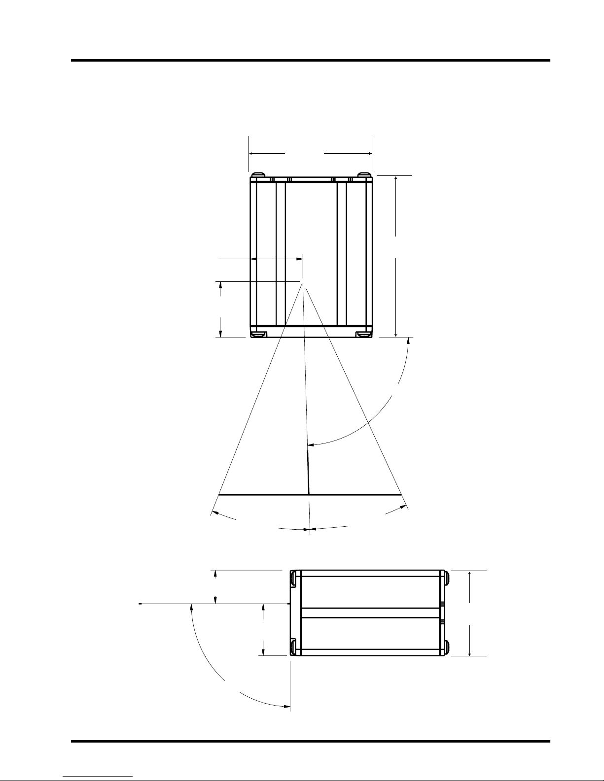
R44-2016 B-1
Appendix B: Mechanical Specifications
0.53"
(13.46cm)
90˚±1.5˚
0.820"
(20.83cm)
23.0˚ ±2.0˚
23.0˚ ±2.0˚
88.3˚±2.0˚
0.086"
(21.84cm)
0.088"
(22.34cm)
1.35"
(3.43cm)
2.53"
(6.34cm)
2.00"
(5.08cm)
Page 46

C-1 LM520 Scanner Integration & Programming Manual
Appendix C:
Factory Default Configuration
Table C-1. Factory Default Configuration
Cmd Description
@Z Enable Scanning of Programming Labels
AE03 Beeper/Good Read duration = 135ms
AF03 Good Read LED = 135ms
BC DisableRead Ve r ifi catio n
BH60 Laser time-out = six seconds
DF Select 9600 baud
EM Set serial data word to 8 bits, one stop bit and no parity
FA Clear Label Formats to Default (%D%)
HA
Disable all Flow Control Protocols. Xon/Xoff is off, CTS mode is None. RTS mode
is forced to RTS high ready to receive (default for CTS)
HN RTS High Indicates Scanning in Progress (default for RTS)
KA Disable Preamble
LB Postamble = CR, LF (0x0D 0x0A)
NA Enable LaserSense mode
ND Disable Continuous Scanning mode
NH24 Double Read timeout = 600ms
NJ/NL Disable No Read timeout
NY Disable No Read message.
OB Enable standard Code 39
OD Disable Code 39 check character
OF Disable transmit of the Code 39 start/stop characters
OK Disable transmission of the Code 39 check character
PA Disable Interleaved two of five
PO Disable transmission of Interleaved 2 of 5 check digit
PQ Disable Standard two of five (STF)
PV Disable transmission of STF check digit
Page 47

R44-2016 C-2
Cmd Description
QC Enable UPC-A
QH Disable expansion of UPC-E
QL Enable UPC-E
QX Disable all UPC 2 and 5 digits supplementals (UPC-A, UPC-E)
QY15 Number of scanning retries to build UPC/EAN supplementals = 15
RC Enable EAN-13
RP Enable EAN-8
RS Disable all EAN 2 and 5 digit supplementals (EAN 8, EAN13)
TC Enable Code 128
TE Disable transmission of Code 128 function codes
UA Disable Code 93
VA Disable Codabar
VC Disable transmission of Codabar start/stop characters
Page 48

D-1 LM520 Scanner Integration & Programming Manual
Appendix D:
LM520 Programming Labels
The most common method of configuring the LM520 scanner is by sending commands from
the host. (see Configuration of the LM520). The bar codes contained in this table are a limited
set of the programmable options.
Table D-1. Programming Labels
Feature Code Bar Code
Reset Factory Defaults Z1
Baud rate - 9600 DF
Data Format - 8 data bits,
1 stop bit, no parity
EM
Enable no flow control HA
Enable software flow
control
HB
Enable hardware flow
control
HL
Enable all symbologies QM
Turn beeper off AE00
Enable label
programming
@Z
Disable label
programming
@Y
³ Z1
³ DF
³ EM
³ HA
³ HB
³ HL
³ QM
³ AE00
³ @Z
³ @Y
Page 49

R44-2016 D-2
Programming Labels (continued)
Feature Code Bar Code
Set beeper duration to
135ms
AE03
Set scanner timeout to
6.0 seconds
BH60
Set scanner timeout to
9.9 seconds
BH99
Set scanner to no timeout
until bar code is decoded
BH00
Scan now, until timeout ZD00
Continuous scan ON NC
Continuous scan OFF ND
LaserSense ON NA
LaserSense OFF NB
LaserSense Range
(Default)
NG60
LaserSense Range Min. NG45
LaserSense Range Max. NG70
³ AE03
³ BH60
³ BH99
³ BH00
³ ZD00
³ NC
³ ND
³ NA
³ NB
³ NG60
³ NG45
³ NG70
Page 50

E-1 LM520 Scanner Inte gration & Programming Manual
Appendix E: ASCII Conversion Table
Table E -1 . ASCII Conversion Table
CHAR DEC HEX CHAR DEC HEX CHAR DEC HEX
NULL 0 00 0 48 30 [ 91 5B
SOH 1 01 1 49 31 \ 92 5C
STX 2 02 2 50 32 ] 93 5D
ETX 3 03 3 51 33 ^ 94 5E
EOT 4 04 4 52 34 _ 95 5F
ENQ 5 05 5 53 35 ` 96 60
ACK 6 06 6 54 36 a 97 61
BEL 7 07 7 55 37 b 98 62
BS 8 08 8 56 38 c 99 63
HT 9 09 9 57 39 d 100 64
LF 10 0A : 58 3A e 101 65
VT 11 0B ; 59 3B f 102 66
FF 12 0C < 60 3C g 103 67
CR 13 0D = 61 3D h 104 68
SO 14 0E > 62 3E i 105 69
SI 15 0F ? 63 3F j 106 6A
DLE 16 10 @ 64 40 k 107 6B
DC1 17 11 A 65 41 l 108 6C
DC2 18 12 B 66 42 m 109 6D
DC3 19 13 C 67 43 n 110 6E
DC4 20 14 D 68 44 o 111 6F
NAK 21 15 E 69 45 p 112 70
SYN 22 16 F 70 46 q 113 71
ETB 23 17 G 71 47 r 114 72
CAN 24 18 H 72 48 s 115 73
EM 25 19 I 73 49 t 116 74
SUB 26 1A J 74 4A u 117 75
ESC 27 1B K 75 4B v 118 76
FS 28 1C L 76 4C w 119 77
GS 29 1D M 77 4D x 120 78
RS 30 1E N 78 4E y 121 79
US 31 1F O 79 4F z 122 7A
SP 32 20 P 80 50 { 123 7B
! 33 21 Q 81 51 | 124 7C
“ 34 22 R 82 52 } 125 7D
# 35 23 S 83 53 ~ 126 7E
$ 36 24 T 84 54 DEL 127 7F
% 3725U 8555
& 3826V 8656
* 3927W8757
( 4028X 8858
) 4129Y 8959
* 42 2A Z 90 5A
+432B
‘ 44 2C
-452D
.462E
/472F
 Loading...