

PS Audio PD-47 Owners manual
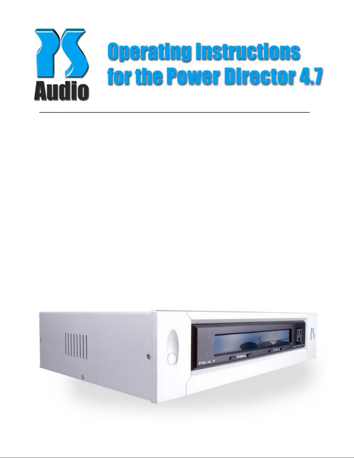
Table of Contents
What’s in the Box
1. What’s in the Box
2. Overview
3. Quick Start Guide
4. Front Panel Controls
4. Display Modes
5. Setup Display Mode
8. Front Panel Utility/Service Outlet
8. DC Trigger Input
9. Trouble Shooting Guide
10. Warranty and Service
11. Notes
12. Contact Information
• One Power Director 4.7
• One 6 foot AC power cord
• One user’s manual
• One warranty card
• One spare 1 amp fast blow fuse.
IMPORTANT: Be sure to save all packing
materials included with your Power Director 4.7
as this will be required if you ever need to ship
the unit for service or modication.
Overview
The Power Director 4.7 is a power distribution
device capable of delivering the highest level of
AC performance to your audio and video components.
• 4 High Current Ultimate Outlets deliver power to
7 Power Port Duplex receptacles
• 4 fully isolated power zones ensure clean power
to all products
• Reduction of AC line noise by 40dB
• Non current limiting
• 3 Levels of surge and spike protection
• High volatage MOV devices, tranzorb diodes and
microprocessor control for surge and spike protection
• Front panel display for systems monitoring and
user interface.
• Readout displays output voltage, amperage, wattage and Power Factor
* Included IR remote control
The PS Audio Power Director 4.7 is designed to
operate as a stand-alone power management
tool, or as a part of a larger power management
system.
In most cases, a single Power Director 4.7 will be
all you will need to operate, protect and improve
an entire home theater or home audio system.
The Power Director 4.7 has 4 electrically isolated
zones and 7 output receptacles, hence the name
Power Director 4.7. Each zone is identical in power
delivery capacity and the zones are isolated from
each other for maximum separation. Three of the
zones (analog, digital and video/other) offer two
output receptacles while the amplifier zone offers
one.
All settings in the Power Director 4.7 are non-volatile. This means the default factory settings, or the
changes made by the user, can never be “forgotten” by the Power Director 4.7, even if it loses AC
power or is placed in storage for a long period of
time.
Each of the four zones can be independently controlled either through the front panel interface, the
included IR remote or the PS bus.
• Independent power control of 4 power zones
• Coaxial and phone surge/spike protection
• Switched, passive or delayed zone power control
• Lower AC impedence for better transients
• Front courtesy receptacle
• PS Audio’s brushed aluminum FRAME chassis.
• Optional rack mount capability.
2

Quick Start Guide
1. Place the Power Director 4.7 where you want
it. The Power Director 4.7 produces little to no
heat, so placement of the Director is a simple
matter of preference on your part . It is safe to
stack equipment up to a total of 20 pounds on
top of the Director.
2. Plug in your equipment. There are four electri-
cally isolated zones on the Power Director 4.7.
Suggestions have been made on the rear panel
as to how the equipment might be grouped
together, but since each zone is identical (except
for the number of outlets) you can plug gear in
wherever it makes the most sense for your system.
We recommend that you set the switches so that
your power amplifier turns on a few seconds after
your preamplifier. This should avoid any turn-on
thumps or pops.
4. Plug in your cable and telephone connections.
There are three CATV connectors and three telephone connectors on the rear panel of the Power
Director 4.7. Plugging your devices into these
connections will insure that they are protected
from surges, spikes and lightning.
The telephone connectors are all in parallel. Plug
your phone line into any one of the three connectors, and the two remaining connectors can be
used as outputs.
For optimum performance, we recommend that
analog equipment (stereo preamps, tuner, tape
deck, etc.) be grouped separately from digital
equipment (AV preamps, CD/DVD players, D to
A converters, etc.). Items with high power consumption (power amps, A/V receivers, projection
T.V.’s etc.) should each use a separate zone if at
all possible.
3. Set the rear panel switches for each of the four
zones. On the far left side of the rear panel of
the Power Director 4.7, there are four separate
slide switches. Each switch represents one of the
Directors four zones and each switch has threepositions. They are:
1. Always On (labeled “ON”). With the switch in
the down-position, the zone will receive power
as soon as the Power Director 4.7 is plugged
into
the wall.*
The CATV (Cable Television or “F type” coaxial)
connectors can be used for three separate feeds
from antennas, cables, satellites, VCR’s etc.
5. Plug the Power Director 4.7 into your AC outlet.
Use the supplied AC power cord, or an aftermarket power cord such as the PS Audio Lab Cable
or Mini Lab Cable for greater performance.
6. The Power Director 4.7 will automatically adjust
to your country’s voltage, from 100 to 240 volts.
7. Turn on the Power Director 4.7 by pushing the
power button located on the far left side of the
front panel.
The four zones of Power Director 4.7 will come
on according to the settings of the rear panel
slide switches. A green light on the right side of
the front panel will illuminate for each of the four
zones as they become active.
2. Switched (labeled “SW”). In the middle
position, the zone will receive power as soon
as the front panel power button of the Power
Director is activated.
3. Delayed (labeled “DL”). In the upper-most
position, the zone will activate three seconds
(the default setting) after the front panel power
button is activated.
*Note about operation:
When the unit is first plugged in, all outputs are off. The
Power Director 4.7 will display the line voltage on the front
panel display. The line voltage must be stable for 10 seconds. If the line voltage is within the default parameters
set by the factory, or user adjusted parameters, the Power
Director 4.7 will turn on. At this time, the Always-On outputs
are activated.
3

Default settings
The Power Director comes from the factory with
standard default settings that should work well for
most situations.
You can return to the default settings at any time
by depressing the Power button and the Mode Up
button at the same time. Hold these two buttons
down for approximately three seconds, until the
display blinks indicating the default settings have
been restored.
Front panel controls
Display Modes
There are six available modes to display on the
front panel of the Power Director 4.7. The Mode
Up and Mode Down buttons cycle you through the
following six modes:
1. Voltage (labeled Volts)
2. Amperage (labeled Amps)
3. Wattage (labeled Watts)
4. Power Factor (labeled PF)
5. Setup Display Modes
6. Display blanking
There are five buttons on the front panel of the
Power Director 4.7.
1. Power
2. Mode Down
3. Mode Up
4. Edit Down
5. Edit Up
Power On/Off
The power button will activate the front panel display and output AC power to any of the four zones
that are set to the delayed (DL) or switched (SW)
position on the rear panel.
Note: any zone whose corresponding rear panel switch is
in the “ON” position will continue to pass power even if the
director is switched off.
Mode
The Mode Up and Mode Down buttons cycle
through the available display modes.
Edit
The Edit Up and Edit Down buttons cycle through
the available options within each display mode.
Voltage
The default display mode indicates line voltage
that is being fed into, and subsequently out of the
Power Director 4.7. The voltage reading typically
has a +/- 0.5% accuracy.
You may note that your line voltage goes up and
down throughout the course of the day and night.
This is not desirable, but it is normal. The addition of a PS Audio Power Plant to the input of the
Power Director will eliminate this problem.
Amperage
Amperage is a measurement of current. This feature displays in real time approximately how much
current your equipment is using. The Director is
capable of either 15 or 20 amps, depending on
its input power connector (15 or 20 Amp IEC) and
the AC source (15 or 20 Amp circuit).
Wattage
This mode will display a close approximation
of the wattage that is delivered to the load. For
example, if the display reads 100 then you are
delivering 100 watts to your equipment. The wattage meter will show the total wattage for all four
zones combined.
Power Factor
Power factor is a measure of how efficiently a
device is drawing power from the wall. A purely
resistive load, like a light bulb (or a heater or
toaster) draws current that is identical in shape
and phase to the sine wave of the AC voltage.
This has a power factor of “1.”
Most electronic equipment, such as a power
4
 Loading...