

Page 1

Instructions for Model P300
The Fan Module upgrade to your unit is a
fairly simple process. If you have any
questions at any time, please contact us
by email, fax or telephone at the numbers
listed at the end of these instructions.
Before beginning the upgrade, you will
need to do the following: Unplug the P300
from the wall. Really unplug it. Take out
the power cord and take out the cords to
your a/v equipment.
Assemble the following tools and work
area:
A clean table to place the P300
while you are working.
A small Phillips head screwdriver
A desk lamp, gooseneck lamp or other
light placed next to the P300 so you
can see what you are doing.
A small cup to hold the screws you are
going to remove from the P300.
The new P300 Fan Module Kit.
INSTALLING THE UPGRADE
You should have the following items:
Page 2
A new PS Audio Fan Module - Bottom
Plate Kit
These instructions.
A Fan Upgrade label for the back of
your P300.
The small gray plastic strip for the
oscillator board.
BEFORE you open the unit:
Are you sure it is FULLY UNPLUGGED?
DID YOU TAKE THE TIME TO READ
THESE ENTIRE INSTRUCTIONS AT
LEAST ONCE BEFORE STARTING?
Turn the P300 upside down, with the feet
facing up. Use your small screwdriver to
take out the 10 small Phillips head screws
on the bottom plate. Save the screws.
NOTE: You do not need to take off the screws
holding down the feet to the Bottom Cover.
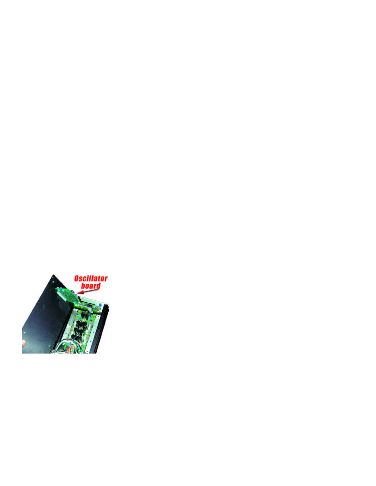
After you take off the ten screws from the
bottom cover, carefully lift the Bottom
Cover straight off. You may notice some
slight resistance. The Oscillator Board in
the P300 is secured by a small, gray plas tic bracket on the inside of the bottom
cover. So, when you lift off the Bottom
Cover, the Oscillator Board may remain
attached to the bottom cover support.
Simply
keep lift ing the
Bottom
Cover
straight
up.
Most
times,
the
Page 3
Oscillator Card will stay plugged into the
P300 Main Board. Sometimes, the
Oscillator Card stays attached to the
Bottom Cover Support.
IF THE OSCILLATOR CARD REMAINS
ATTACHED TO GRAY PLASTIC SUP PORT ON THE BOTTOM COVER – Read
this Section Carefully:
Pull the Oscillator Board off the gray plas tic support. Be careful to touch the Board
only on it edges. You need to reinsert the
Oscillator Board into its socket on the
P300 main board.
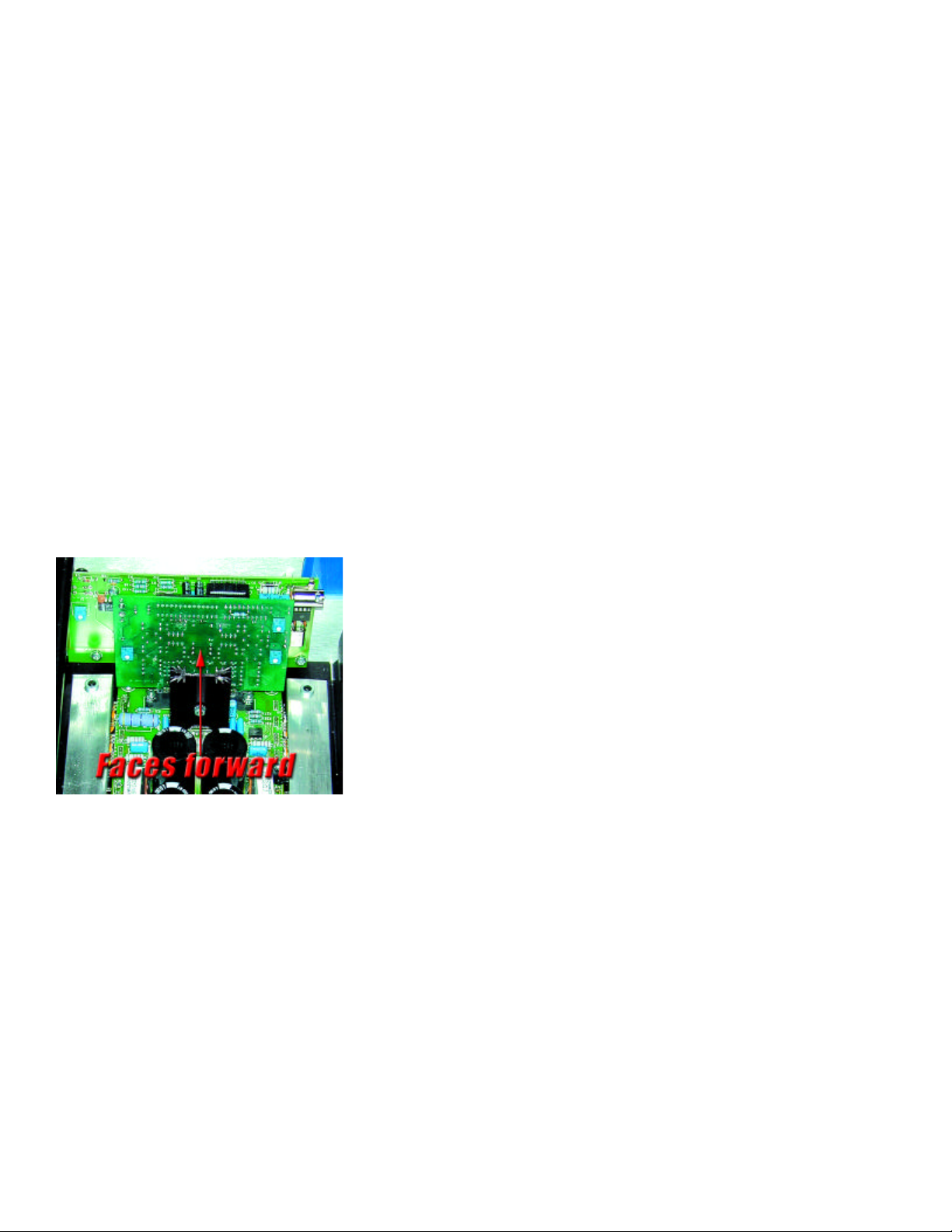
The electronic components on the
Oscillator Board MUST FACE
FORWARD, toward the faceplate of the
P300. DO NOT insert the Oscillator
Board so that the electronic components
face the rear of the P300.
Insert the Oscillator Board into its socket
on the Main Board STRAIGHT DOWN.
DO NOT ROCK THE CARD back and
forth. Insert it STRAIGHT. The Board
must NOT be inserted at an angle.
IF THE OSCILLATOR CARD REMAINS
IN THE P300 ATTACHED TO THE MAIN
BOARD.
Page 4
Great! Simply leave it attached. Make
sure it is fully seated in its socket by giving a little push DOWN on the top of the
Board.
INSTALL THE FAN PLUG.
On the new Fan Bottom Plate, there is a
white set of wires and a loose white plug.
This plug is inserted into a socket on the
main board of the P300.
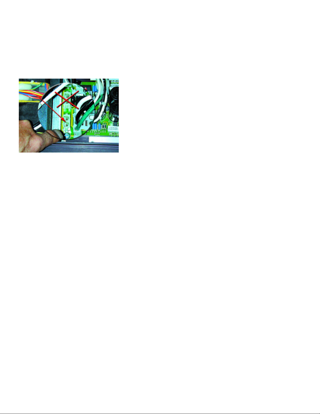
There are two empty sockets on the P300
main board; both are located near the
transformers. One socket is located in the
center on the back edge of the board. Do
Not Plug the Fan Module into this Socket.
The other socket is off to one side of the
back edge of the P300 main board. THIS
IS THE CORRECT PLUG. Plug the fan
board into this socket.
The socket and plug are keyed so they
will only fit in one direction. Press the plug
into until it snaps.
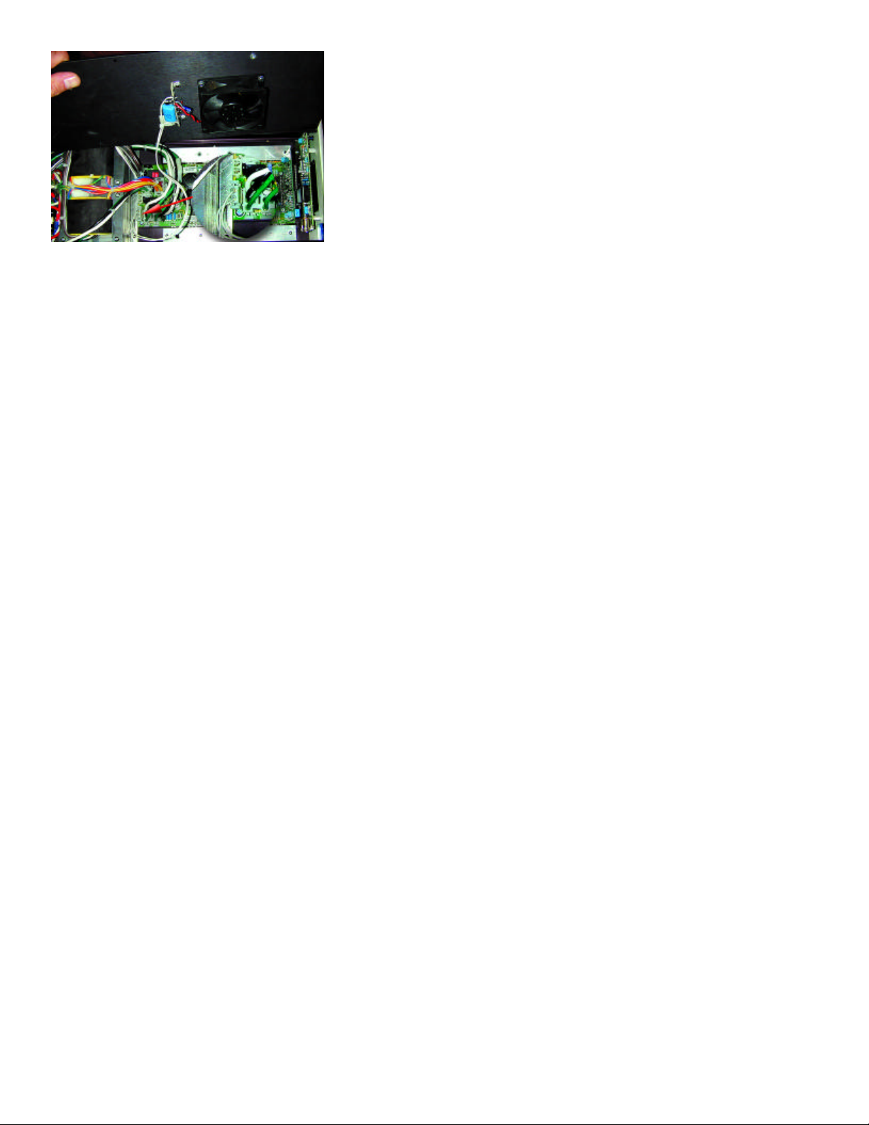
Install the New Fan Bottom Plate.
Now that you have plugged in the fan
wire, you can put the bottom panel back
on the P300. The Fan goes toward the
FRONT of the P300 and the empty hole
and grill toward the rear of the P300.
Before reinstalling the Bottom Plate,
Page 5
attach the new gray plastic strip to the top
of the oscillator board. The groove in this
support strip aligns with the edge of the
Oscillator Board.
Now the gray plastic strip is attached, via
the groove, to the top of the oscillator
board, in the approximate middle of the
board.
Remove the piece of tape on the gray
plastic piece, exposing the adhesive.
Carefully align the bottom cover with the
chassis, and press down on the bottom
cover so as to afix the adhesive to the
inside of the bottom plate.
The new bottom panel should line up just
like the former bottom panel. It should be
flush all around.
Loosely insert the ten small Phillips head
screws. Make sure the bottom cover is
seated and flush, then fully tighten the
screws.
Turn the P300 over and perform the following tests:
Plug the P300 into your source of
power
Turn on the P300 unit with the switch
Page 6

on the back panel. Up is ON.
Turn on the unit with the front panel
switch. The P300 front panel should
indicate “60.” If it does, the P300 is full
operational and ready to enjoy.
OPERATING NOTES
The Fan Module was designed to protect
the INTERNAL components of the P300
when it is being driven in the upper range
of its limits. The top of the P300 is a
large heat sink and will continue to be
warm to hot, regardless of the fan
upgrade. The fact that the top is warm
DOES NOT MEAN THE FAN IS NOT
WORKING.
The fan pulls hot air out of the P300.
Therefore, be careful that heat sensitive
materials are not under the fan output.
NEVER place the P300 on a soft surface,
such as a carpet. All P300’s, especially
those equipped with the fan upgrade,
should be placed on a solid surface.
The new feet on the P300 Fan Upgrade
Module have been carefully chosen for
your unit. Both the aerospace specifica tion material in the feet as well as its
design is engineered to reduce vibration
transmitted both TO and FROM the P300.
Place all supports for the P300 under the
new feet.
www.psaudio.com
877-772-8340 within the United States
720-406-8946 outside the United States
720-406-8967 Fax
[email protected] e-mail
Page 7

 Loading...