

Page 1

PS Audio MultiWave®Upgrade Instructions for Model
A small Phillips head screwdriver for the P300 or the enclosed red handled Allen wrench for the P600 and P1200.
P300, P600, P1200
The MultiWave upgrade to your unit is a fairly simple process. If you have any
questions at any time, please contact us by e-mail, fax or telephone at the
numbers listed at the end of these instructions.
Overview
What you will be doing is rather simple. In short, these are the steps neces sary to install MultiWave:
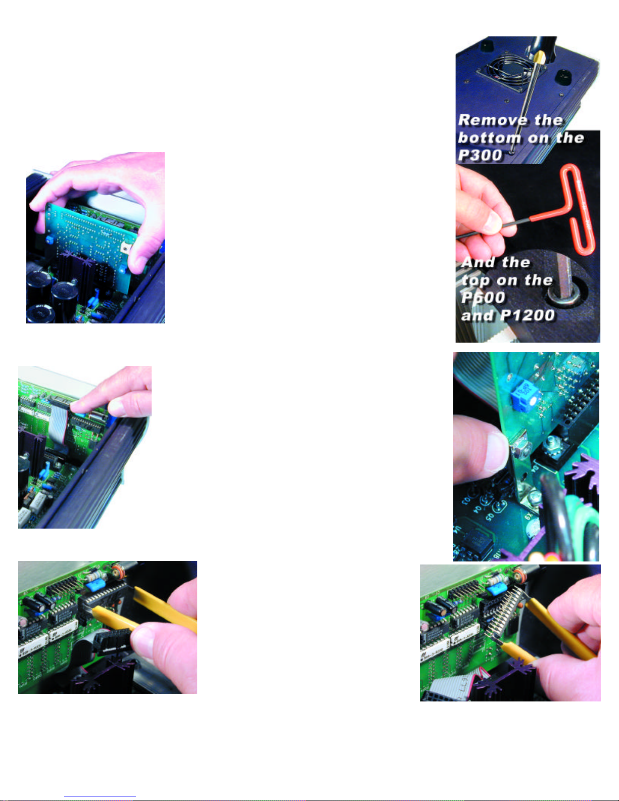
1. On the P300, remove the bottom cover. On the P600 and P1200, remove the top cover.
2. Pull the socketed oscillator board out.
3. Pull the connecting plug out.
4. Remove a socketed integrated circuit.
5. Put a new integrated circuit back into the socket.
6. Replace the connecting cable.
7. Insert the new oscillator board.
8. Replace the bottom cover or the top cover, depending on your model.
9. You are done.
When you are ready, please follow these step by step instructions:
Before beginning the upgrade, you will need to perform the following activities:
1. THE NIGHT BEFORE. Unplug the Power Plant the night before you plan to do the upgrade. Really unplug it!
Take out the power cord and take out all the power cords to your a/v equipment. By letting the Power Plant sit
overnight, most of the energy stored in the power supply will drain away. This is important.
2. THE DAY OF THE UPGRADE Assemble the following in your work area:
a. A clean table to place the Power Plant on while you are working.
b.
c. A desk lamp, gooseneck lamp or other light placed next to the Power Plant so you can see what you are doing.
While this upgrade process is easy, you must be able to see exactly what you are doing.
d. A small cup to hold the screws you are going to remove from the Power Plant.
e. The MultiWave Upgrade Kit.
3. INSTALLING THE UPGRADE
a. Open the Upgrade Kit. You should have the following items:
b. A 6 inch by 6 inch box which contains a pink bubble wrap bag. Do bot take anything out of the bag at this time.
In the pink bag is:
1. The new PS Audio Low Distortion Oscillator Board
2. The Display Microprocessor chip stuck to a piece of black anti-static conductive foam.
3. A yellow handle "Chip Puller" which looks like a set of small tongs.
4. A red handled Allen wrench (for P600 and P1200 only)
5. A plastic "dentist's mirror."
6. These instructions.
7. A MultiWave label for the back of your Power Plant.
4. BEFORE you open the Power Plant:
a. Are you sure it is FULLY UNPLUGGED?
b. Are you sure it has been unplugged from the wall for at least 12 hours?
c. Did you take the time to read these instructions all the way through at least once?
5. Turn the P300 upside down, with the feet facing up. For the P600 and P1200, keep them upright so you have easy access to their top. Use
your small screwdriver to take out the 10 small screws holding on the bottom plate on the P300, or use the red handled Allen wrench to remove
the Allen screws affixing the top cover of the P600 or P1200. Save the screws in a safe place. NOTE: You do not need to take off the screws
holding down the feet to the Bottom Cover on the P300.
6. On the P600 and P1200, remove the top cover and set it aside. On the P300, after you take off the ten screws from the bottom cover, CARE-
FULLY and SLOWLY lift the Bottom Cover straight off. You may notice some slight resistance. The Oscillator Card in the P300 is secured by a
small gray plastic bracket on the inside of the bottom cover. So, when you lift off the bottom cover, the Oscillator board MAY remain attached to
this bottom cover support. Simply keep lifting the Bottom Cover straight up.
7. Most times, the Oscillator Card will stay plugged into the P300 Main Board. Sometimes, the Oscillator Card gets unplugged from the P300
Page 2
main board and instead stays attached to the gray plastic support. The Oscillator board in the P600 and
P1200 is held in place with screws and will not come out after the top cover has been removed.
8. REMOVING THE OLD OSCILLATOR CARD ON THE P300
a. If the oscillator card remains attached to the gray support on the bottom cover:
Simply remove the Card from the support and set it aside. You will be sending this old Oscillator Card back
to PS Audio in the postage paid box (US residents).
b. If the oscillator card remains attached to the motherboard:
Simply grab the card with two fingers and lift straight up to remove. Do not rock the card back and forth to
remove it! Set it aside. You will be sending this old Oscillator Card back to PS Audio in the postage
paid box (US residents).
9. Removing the oscillator card on the P600 and P1200.
Remove the two screws and nuts holding the oscillator board in its
socket. Then, Simply grab the card with two fingers and lift straight up
to remove. Do not rock the card back and forth to remove it! Set
it aside.
You will be sending this old Oscillator Card back to PS Audio in the
postage paid box (US residents).
10. Replacing the front panel microprocessor “chip”.
First, we need to take out the Old Microprocessor Chip.
a. This is the part that takes a little patience and concentration. You
are going to remove the front panel microprocessor chip and replace
it with a new one.
b. First locate the Front Panel Board. This is the small computer board
that is screwed to the back of the Power Plant's Front Panel.
c. Next, unplug the small cable on the Front Panel Boardthat connects to the Power Plant's main board.
This takes your attention, but must be done before you can remove and replace the Front Panel
Microprocessor.
d. The Connecting Cable is flat and gray, with a rectangular black con nector. Using your thumb and forefinger, pull the connector of the
Connecting Cable off the Front Panel Board.
e. Next, locate the Microprocessor on the Front Panel Board. The
Microprocessor is the only computer chip on the Front Panel Board that
is in a socket.
f. Next, take the Chip Puller enclosed. The Chip Puller will be used to
carefully pry out the oldMicroprocessor. Notice the Chip Puller has two
small prongs.
g. Put the two prongs of the Chip Puller between the Chip and the socket on the left and right side. There is a small gap between the Chip and
the socket for you to get in the prongs of the Chip Puller. It may take a
little wiggling of the Chip Puller to get its prongs under the Chip.
h. Next, squeeze the Chip Puller together and pull the Microprocessor
Chip straight out of its Socket. It may take a tug. Pull straight back. When
the OLD Microprocessor chip pops out of its Socket, lay it out of the
way.
Great work! You are almost done. Take a break.
Next, we need to install the New Front Panel
Microprocessor Chip. Carefully open the sealed
end of the pink bubble wrap bag.
Do not take out or touch the microprocessor chip
yet.
Just open the pink bag. You MUST first make sure
you have discharged all static from yourself. This is
not difficult. The easiest way of doing that is to touch
a metal object. A metal table or chair leg is good. Or
an exposed metal part of some appliance that is plugged into the wall, such as the table lamp you
should have lighting your work area.
i. After you have discharged yourself of any static electricity, carefully remove the new Processor Chip from the pink bag. The Chip is pressed
to a small piece of black conductive foam. This special foam protects the Chip from static.
Do not remove the chip from the anti static foam yet.
Page 3

j. Notice that the Chip has a tiny half moon, cut-out or "dimple" on one side. This cut-out must face to the
righton the P600 and P1200 and the left on the P300 when the Chip is installed. Now, carefully use your fin-
gers to pull the Chip straight out of the black protective foam. Yep, you can use the Chip Puller for this if you
like. The key is pulling the Chip straight out of the foam so that we do not bend any of the little legs.
k. After you pull the Chip out of the foam, Lay it so it rests on its feet on the black foam . It will look a
lot like a bug - a healthy bug with straight legs. If any of the legs are not straight, use a finger nail to straight -
en it.
OK, I lied; this next step really requires your careful attention.
DO NOT RUSH THIS NEXT STEP. Please read this next
section again before you go on.
l. Do you have a light shining inside the Power Plant and is it well lit? Do you have your reading
glasses on? Just checking.
m. You are going to next insert the Chip into the socket. Do this by grasping the small sides of
the Chip with your thumb and forefinger.
First, make sure the chip is facing the correct way for the model you have. On the P300, the writing on the chip will be right-side-up. On the P600 and P1200, the writing on the chip will be upsidedown.
Now, carefully line up the legs of the Chip with the holes in the socket. BE VERY CAREFUL. Only
lightly press the Chip into the socket at this time - just enough for the socket to hold the Chip. You
just want to get the legs started.
Do not press hard on the chip at this time.
n. You must now make sure each leg of the microprocessor is inserted in the corresponding
socket hole. That's what the little dentist's mirror is for.
o. Using the dentist's mirror, carefully check that each leg of the microprocessor is aligned and
going straight into its matching hole on the socket. You
should be able to see the pins on the top of the socket with
your eye. The dentist mirror will really help with the lower
set of pins.
p. When you are sure that each leg of the Microprocessor is
straight and lined up correctly into its very own hole, press
the Microprocessor Chip down into the socket. The Chip
will seat almost flush into the socket.
q. Now, use the mirror again to inspect the Microprocessor
Chip and socket. The Microprocessor MUST be flush
in the socket and no pins should be bent or coming out of
the socket.
WHEW! That was the tricky part. You are well on your way
to becoming a certified computer technician. Time for another break. Listen to some music. Oh,
sorry, forgot your system was unplugged while you upgrade the Power Plant.
Putting it all back together
11. Replace The Front Panel Cable.
a. You also need to be careful at this step. The Front Panel Cable Connector must be aligned cor-
rectly when reinstalled. There are no keys to make it easy
to line up the cable connector.
b. Grip the plastic end of the cable and line it up with the
pins on the Front Panel Board. Just lightly press the connector on at this time.
c. Make sure that the connector is not off a row of pins to
the left, to the right, below or above. Take your time and
make sure each pin on the Front Panel Board aligns with
the Connector. Use the dentist mirror again. Who knows
when you will have the next chance!
d. When the Connector is correctly lined up on the pins, it will
press back on all the way with only slight finger pressure.
e. With the front panel connector on, check your work one
more time. Use the dentist mirror, again. Wow, you're a
pro at this! Place the mirror below the connector to make
sure the pins are all correctly in place. If the pins are not
lined up, no big deal. Just pull off the connector and reinsert.
Page 4

We are coasting to the finish now.
12. Replace the Oscillator Board
a. Read this entire section before you attempt to replace the oscillator board!!
b. Now take the NEW Oscillator Board from the pink anti-static bag. Be careful to only touch the
edges of the new Board. Notice the sticker on the rear of the Board. One more time: the sticker
is on the REAR of the Board.
c. The new Board must only be inserted in one direction.
d. The electronic components on the new Oscillator Board MUST FACE FORWARD, toward the
faceplate of the Power Plant. NEVER, NEVER insert the Oscillator Board so that the electronic
components face to the rear of the Power Plant. Remember the little sticker on the REAR of the
Board.
e. Insert the New Oscillator Board into its socket on the Power Plant's Main Board by pushing
straight down.
DO NOT ROCK THE CARD back and forth. Insert it straight. The Board must not be inserted at an
angle.
f. If you are working on a P600 or a P1200, replace the two small screws and nuts that hold the oscillator board in place.
13. Inspect your work
You are almost finished. Carefully inspect you work one more time before you button up!
a. Make sure that the NEW microprocessor on the Front Panel Board is inserted correctly. Use that mirror if you need to!
b. Is the half moon of the front panel chip you inserted going in the same direction as the half moon of the
other chips on this same board? If not, you’ve done this step incorrectly.
c. Make certain the Front Panel Cable Connector is inserted correctly with no exposed pins.
d. Be sure the New Oscillator Board is fully inserted with the electronic components facing the FRONT of
the Power Plant and the sticker facing the REAR.
14. Replace the bottom cover or the top cover (depending on your model)
a. Before reinstalling the bottom cover of the P300, notice the gray support strip on the inside of the bot-
tom cover. The groove in this support strip aligns with the edge of the Oscillator Board. Looking at the unit
from the side, place the bottom cover on top of the P300. Align the top of the Oscillator Board with the
groove in the support strip. When they are aligned, press down on the bottom cover. It will snap into place
when properly aligned. Sorry, the trusty dentist's mirror will not help you here.
b. Replace the screws in the bottom cover of the P300.
c. Place the MultiWave sticker on the back of your Power Plant.
d. YOU'RE DONE! Really. But keep that dentist's mirror close by. Who knows what computer chips or
teeth might need inspecting.
15. Testing The Power Plant
To make sure everything is ship-shape, perform the following tests:
a. Plug the Power Plant into your source of power. Do not plug anything into the back of the unit at this time.
b. If you have a P300, turn on the unit with the switch on the back panel. Up is ON. If you have a P600
or P1200, the unit is on the moment you plug it in to the wall socket.
c. Next, press the front panel power button. The Power Plant front panel display should read "Sin." If it does, the Power Plant is fully operational and you are now a certified PS Audio MultiWave Upgrade Installer. We are proud of you.
16. Sending the Old Oscillator Board Back to PS Audio.
a. Please return the old oscillator board to PS Audio within 45 days of receiving the MultiWave update kit. This applies only in the United States.
Should you fail to return the Oscillator board with 45 days, PS Audio will charge your credit card for $50, the value of the old oscilla-
tor board. If you live outside of the United States, you or your dealer are responsible for returning the old board to us for credit.
b. Sending the old board back could not be easier. Simply place the old oscillator board in the pink static protection bag. Place the pink bag in
the 6 inch square box and seal with a piece of strong tape. The return label to PS Audio is already attached.
c. Just drop the box in any USPost Office mailbox. No need to add postage. PS Audio pays the postage. The box is marked with your order
number so we can check in your old board when it arrives.
Now, hold on to your favorite listening chair and experience MultiWave.
Peter and I are quite sure you will be as amazed as we were the first time we listened.
If you have any questions about the installation process, stop and contact us. We are here to help.
E-mail customerservice@psaudio.com anytime. We will get back to you within 24 hours. Or call us at 720-406-8946 from 9 to 5, Mountain
Daylight Time. Our fax number is 720-406-8967 if you prefer.
Page 5

Good listening!
Paul McGowan
CEO
PS Audio, Inc.
Page 6

 Loading...