

Page 1
1
Wireless RF interlink baseplate for
LIFESAVER 5800 series Smoke Alarms.
You do NOT need a home wi-fi system
to use these units. Multiple wireless units
create their own independent wireless RF
interlink network.
1208-7204-00
RF Interlink Baseplate User Guide
Model LIFWMB2
Page 2

2
Thank You for Choosing PSA
This LIFESAVER LIFWMB2 base plate is capable of wirelessly interlinking other Lifesaver 5800 series
mains powered smoke alarm fitted with LIFWMB2 wireless base and Lifesaver LIF10YPEW wireless
smoke alarms. When one RF interlink unit sounds an alarm, all other compatible RF units in the RF
interlink network will alarm.
Read Section 2: Activation And RF Interlink Network, before powering the units. You do
NOT need a home wi-fi system to use these units. Multiple wireless units create their own
independent RF interlink alarm network.
This wireless baseplate is powered by the smoke alarm. In the event of a mains power failure, the
backup battery of the smoke alarm will ensure the wireless network continues to operate.
NOTE: A NETWORK IS LIMITED TO 24 ALARMS
Teach children how to respond to the alarm and that they should never play with the unit.
Your PSA LIFESAVER Smoke Alarm was designed for use in a residential environment. It is not designed
for use in a recreational vehicle (RV) or boat.
Note: Please thoroughly read this user guide and save the document for future reference and
to pass on to any subsequent owner.
IMPORTANT: Additional markings can be found on the back of the unit.
Page 3

3
Contents
1. Introduction, Product Features And Specifications ..................................................................... 1
2. Activation and RF Interlink Network ......................................................................................... 2
2.1 Setting Up an RF Interlink Network (Enrolment).................................................................. 2
2.2 Adding Another Device to an Existing RF Interlink Network ............................................... 3
2.3 Resetting a Device’s RF Interlink Settings ............................................................................ 4
2.4 Enrolling the RF baseplate to the LIF10YPEW RF interlink smoke alarm............................... 5
3. Wireless FAQs............................................................................................................................ 6
4. Installation Instruction .............................................................................................................. 8
5. Operating, Testing and Alarm Characteristics .......................................................................... 11
6. Cleaning Your Alarm .............................................................................................................. 12
7. Good Safety Habits ................................................................................................................. 13
8. Limitations Of Smoke Alarms .................................................................................................. 14
9. Warranty and Liability ..............................................................................................................15
10. Product warranty registration .................................................................................................. 16
Page 4
1
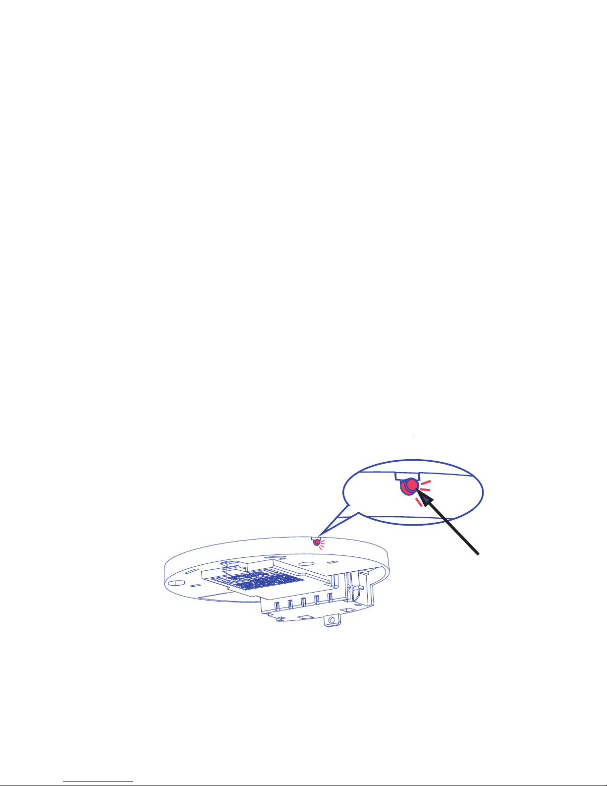
LINK button
1. Introduction, Product Features And Specifications
Introduction
Installing this wireless interlink baseplate onto the PSA Lifesaver 5800 Series smoke alarms allows the smoke
alarms to be interconnected wirelessly. When one smoke alarm activates, the RF interlink will trigger other
smoke alarms in the same RF network.
Product Features and Specifications:
• Temperature: Operating Range: 0 °C to 45 °C
• Humidity: Operating range: up to 95% RH non-condensing
• Smoke Alarm Power: 240VAC 50Hz 10mA
• Radio Module Power: 9VDC from smoke alarm
• Radio Frequency 918MHz.
• Range: 100m line of sight. 30m indoors. Distances will vary depending on walls and obstructions.
• Design for LIFESAVER 5800 series 240VAC smoke alarms.
• Compatible with LIFESAVER LIF10YPEW 10 Year wireless smoke alarm.
• Connect up to 24 smoke alarms
• Approved to AS/NZS4268:2017
Page 5

2
2. Activation and RF Interlink Network
This model is capable of interlinking with other PSA LIFWMB2 models in domestic residential applications. When
one RF interlink unit sounds an alarm, all other compatible RF units in the RF interlink network will alarm. Follow
the steps in section 2.1 to interlink up to 24 units in your interlink network. If you have problems during setup,
see section 2.3 to start over.
NOTE : Wireless units will emit a series of LED flashes as the unit(s) search for an RF interlink network.
If you are intending to use wireless units without the wireless function, ignore these notifications, and
the wireless function will eventually turn off. You can turn the wireless function on again at a later
date if desired. See Section 2.2.
Definitions of key terminology:
Coordinator: The wireless network master unit that is the key communicator with the other wireless
units. This assignment remains until the coordinator is reset (section 2.3). The coordinator unit should
be installed in a central location of the residence.
RF Device (RFD): The other wireless units that connect with the Coordinator.
General Reset mode: Resets a unit to when it was powered on for the first time after being removed from the
package.
2.1 Setting Up an RF Interlink Network (Enrolment)
For easiest first-time setup, we recommend unpacking all units together on a desk, table, or counter
and using the steps in the following table. If you prefer to install the alarms on the ceiling before
enrolment, attach all baseplates to the ceiling first, and then choose a central location unit to start with
step 2 below.
User Input Detector Response Timeout
Step 1 Unpack all units and power the
smoke alarm on battery.
Step 2 Connect the first smoke alarm to
the LIFWMB2 baseplate.
LIFWMB2 powers up - Red LED flash
one second ON one second OFF
Step 3 2 LINK button presses on the RF
baseplate.
Two quick Red LED flashes every 2
seconds to indicate unit is configured as a Network Coordinator and
Join Mode is Open
Join Mode will timeout in 15 minutes
Page 6

3
2.2
Adding A Detector To An Existing RF Interlink Network
At some point, you might want to add another smoke alarm unit to your existing RF interlink
network for additional protection, or to replace an old unit. Follow the steps in the following table.
User Input Detector Response Timeout
Step 1 2 LINK button presses on any
unit in the network.
Unit will respond with two quick
flashes every 2 seconds if it is the Coordinator of the Network; three quick
flashes every 2 seconds if it is an RFD in
the Network - Join Mode is open.
Join Mode will timeout in 15
minutes
Step 2 Power up unit(s) being added
by connecting the smoke
alarm to the RF baseplate. For
previous units that have been
reset, press button twice to
enter join mode.
Red LED flashes three times every 2
seconds to indicate it is configured (as
an RFD) in the network
Join Mode will timeout in 15
minutes
Step 3 After new unit(s) have joined,
press LINK button twice on
any unit in the network to
close Join Mode.
Red LED on each unit will power off
indicating Standby Mode
Join Mode will timeout in 15
minutes
Step 4 Follow installation instructions
in section 4.
User Input Detector Response Timeout
Step 4 Connect each additional smoke
alarm on its RF baseplate.
Red LED on each unit will initially flash
one second on and one second off.
when each unit joins network and red
LED flashes three times every 2 seconds
to indicate it is configured as an RFD in
the network
Join Mode will timeout in 15 minutes
after last unit joins.
Step 5 After all units have joined,
press LINK button twice on the
baseplate.
Red LED on each unit will power off
indicating Standby Mode
Step 6 Follow installation instructions
in section 4.
Page 7

4
2.3 Resetting A Unit’s RF Interlink Feature (General
Reset mode)
This section will explain how to perform a general reset of a unit, which starts the unit over as if it
were powered up for the first time. It also explains how to remove a unit from a network if needed.
Follow the steps in the table below if one of these conditions occurs:
* If you have problems or become confused during initial RF Interlink enrolment.
* If a unit is consistently out of range and needs to be removed from the RF Interlink Network.
* If you decide to remove a unit from your RF Interlink Network and enrol it in another RF Interlink
Network (at a friend or family’s location, for example).
User Input Detector Response Timeout
Step 1 2 LINK button presses to open join mode
on unit to reset or remove..
Unit will either:
2 Red LED flashes every 2 seconds - Coordinator
3 Red LED flashes every 2 seconds - RFD
Red LED flash 1s on 1s off - searching for network
Network will enter join mode and display 2 or 3 flashes
respective to their current states (Coordinator or RFD).
Step 2 Press and Hold LINK Button on unit to
reset or remove.
Red LED will blink four times, twice - indicating the unit has
been reset. Unit is in general reset condition and is now in
stand alone mode. Unit will not join a network until network
opened at this specific unit with two button presses.
Step 3 2 LINK button presses on any other unit
in the network to close Join Mode.
Red LED on each unit will power off indicating Standby Mode
Step 4 a. If trying to join a network, start over
with section 2.2. If problems still occur,
call customer support.
Page 8

5
User Input Detector Response Timeout
Step 1 Power the smoke alarm on battery and
connect the LIFWMB2 baseplate.
LIFWMB2 powers up - Red LED flash one second ON
one second OFF.
Step 2 2 LINK button presses on the RF
baseplate.
Two quick Red LED flashes every 2 seconds to indicate
unit is configured as a Network Coordinator and Join
Mode is Open.Three red LED flashes indicate unit is a
network RFD and Join Mode is Open.
Join Mode will
timeout in
15 minutes.
Step 3 Power the new LIF10YPEW smoke alarms
by connecting them to the mounting
base.
Red LED on each unit will initially flash one second on
and one second off. When each unit joins network and
red LED flashes three times every 2 seconds to indicate
it is configured as an RFD in the network.
Join Mode will
timeout in
15 minutes after
last unit joins.
Step 4 After all units have joined, press LINK
button twice on the baseplate.
Red LED on each unit will power off indicating Standby
Mode.
Step 5 Follow installation instructions in
section 4.
2.4 Enrolling the RF baseplate to LIF10YPEW RF
interlink smoke alarm
This section explains how to setup the mains powered smoke alarm with the RF baseplate to
wirelessly connect with LIFESAVER model LIF10YPEW RF interlink smoke alarms. The enrolment
process is similar to previous steps.
Page 9

6
3. Wireless FAQs
ID FAQ Answer
1 How does “desk enrolment” work? Connect first unit onto smoke alarm to power it up. Push LINK button
twice to open network. Power up remaining units. Wait for each unit to
join. Push LINK button twice to close network. See section 2.1.
2 What happens if units are powered
up for the first time but no buttons
are pressed?
Units will search for a network for 15 minutes after which all units will go
into standby and LED off.
To recover, two quick LINK button presses to restart join mode on all units
that have timed out.Return to section 2.1.
3 What happens if a RFD doesn’t find
a network during the enrolment
process (out of range, defective
radio, not made coordinator)
Unit will go into standby and LED will flash every 2 seconds indicating
Network not found. The unit will then become a stand alone smoke alarm
with no interlink.
4 What happens if a Coordinator
doesn’t find any RFD to join after
being set to coordinator.
Coordinator times out after 15 min, becomes a stand alone smoke alarm
with no interlink.
RFD times out after 15 minutes, becomes a stand alone smoke alarm.
Units LED will flash every 2 seconds indicating that they are not joined.
5 What happens if an RFD drops from
the network?
The RFD will enter fault mode after approximately 30min.
6 What happens if an RFD drops
from the network and comes back
online?
Nothing within ~30min.
After 30 minutes it will go into error mode - network fault. Once the RFD
comes back online, two LINK button presses on any unit in the network
will allow it to re-join.
7 What happens if the coordinator
drops from the network?
IF no other units can hear the coordinator AND RFD1 can hear all the
others: RFD unit 1 becomes the coordinator after 30 min and other RFD’s
will re-join.
Page 10

7
Wireless FAQs
ID FAQ Answer
8 What happens if the coordinator
drops from the network and comes
back online?.
Nothing within 30min. After 30 min, push LINK button twice, and then
push /hold LINK button for approx 4 seconds. Unit is reset. Push LINK
button twice to reopen network and rejoin. See section 2.3. (assuming
RFD1 unit 1 took over). The ex-Coord unit can be joined to the network as
RFD unit, network issue clears.
9 How can a unit be added to the
network?
Push LINK button twice on any existing networked unit. Power on new
unit and wait for it to join. Push any LINK button twice to close network.
See section 2.2.
10 Can the enrolment process be
reset/restarted?
Yes. Push LINK button twice to open network. Push /hold button for
approx 4 seconds. Push LINK button twice to reopen network at that
unit. See section 2.3.
11 Is there a way to get more informa-
tion about a trouble status?
In fault mode press LINK button for red LED error code. Count the number
of Red LED flashes and report to customer support.
12 What happens if the user puts 2
units into coordinator mode during
desk enrolment?
The user will have 2 coordinators. Corrective action: See section 2.3 to
reset one of the coordinators to become an RFD.
13 Is it possible to check how many
units are enrolled into the network
While in join mode, press and release LINK button on any joined unit. LED
will blink out number of units.
14 Is it possible to check if a unit is the
coordinator or an RFD
With two LINK button presses (setting the unit to Join mode) there will be
a different blink pattern to identify a Coordinator or a RFD:
Unit will respond with two quick flashes every 2 seconds if it is the
Coordinator of the Network, three quick flashes every 2 seconds if it is an
RFD in the Network
15 If the mains power to the smoke
alarm is turned off will the RF
baseplate remain on?
Yes, the RF wireless baseplate will remain on as it is powered by the
smoke alarm backup battery.
Page 11
8
4. Installation Instruction
PSA recommends to connect alarms and bases to a dedicated circuit that is separately electrically
protected. This helps minimise interference (EMI) on alarm interconnect line from CFL’s, dimmers,
LV transformers etc.
• This wireless base will not detect smoke or heat and must be installed in conjunction with the
specified alarms. Only connect to the specified models of smoke or heat alarm. Do not connect to
any other brand of alarm/auxilary device unless approved by PSA.
• The earth terminal connection provided is for termination purposes only and is NOT electrically
connected within the sealed alarm / base units.
WARNING: THIS Wireless base MUST BE INSTALLED BY QUALIFIED (LICENSED)
ELECTRICIANS ONLY.
Wiring Instructions:
• In the interests of safety, this wireless base and all wiring must be installed by a licensed electrician
in accordance with the relevant requirements of the SAA Wiring Rules - AS3000.
• This wireless base plate can only interconnect with compatible smoke alarm. Interconnection with
other brands may cause damage or result in a shock or fire risk and void warranty.
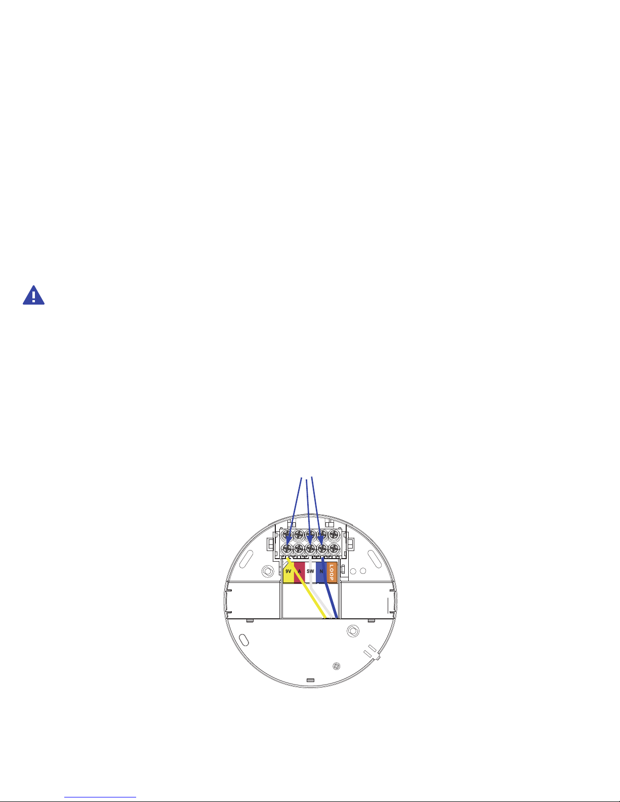
• There are wires that are pre-cabled to the terminal. DO NOT REMOVE OR DISCONNECT THESE
CABLES.
DO NOT REMOVE
Page 12
9
• There are five terminals in the supply terminal block, marked 9V, A, SW, N and LOOP. It is important
that the alarm be wired correctly to ensure correct operation. Incorrect wiring to the Smoke Alarm
will damage the unit and void the warranty.
• Terminals on the back of base plate are marked and colored as follows:
MARKINGS
(Yellow) 9V 9VDC POSITIVE POWER SOURCE
(Red) A ACTIVE
(White) SW SWITCH WIRE (FOR INTERCONNECTION ONLY)
(Blue) N NEUTRAL
(Orange) LOOP DEAD TERMINAL
WARNING: Connecting the Switch wire terminal to any other supply conductor may
result in damage to the alarm, failure to operate or shock hazard and void the warranty of
the alarm.
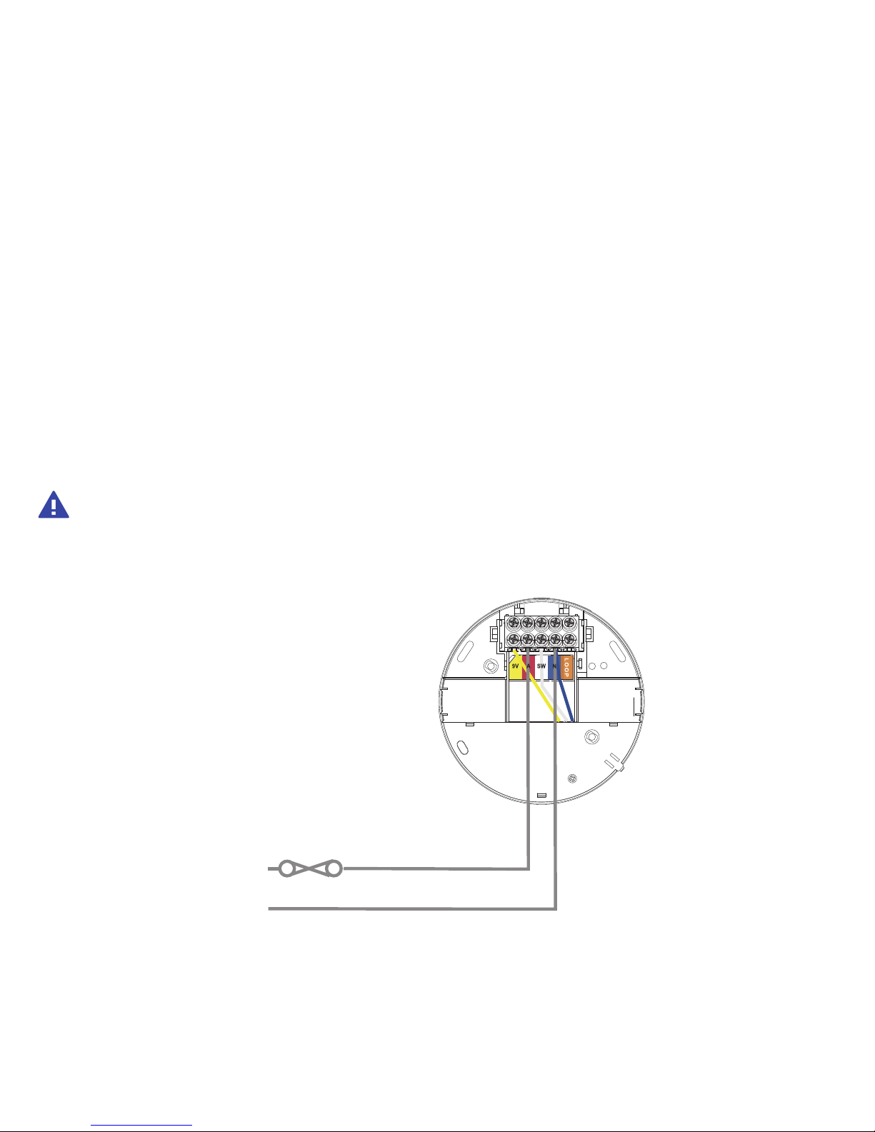
A
N
FUSE OR CIRCUIT BREAKER
Page 13
10
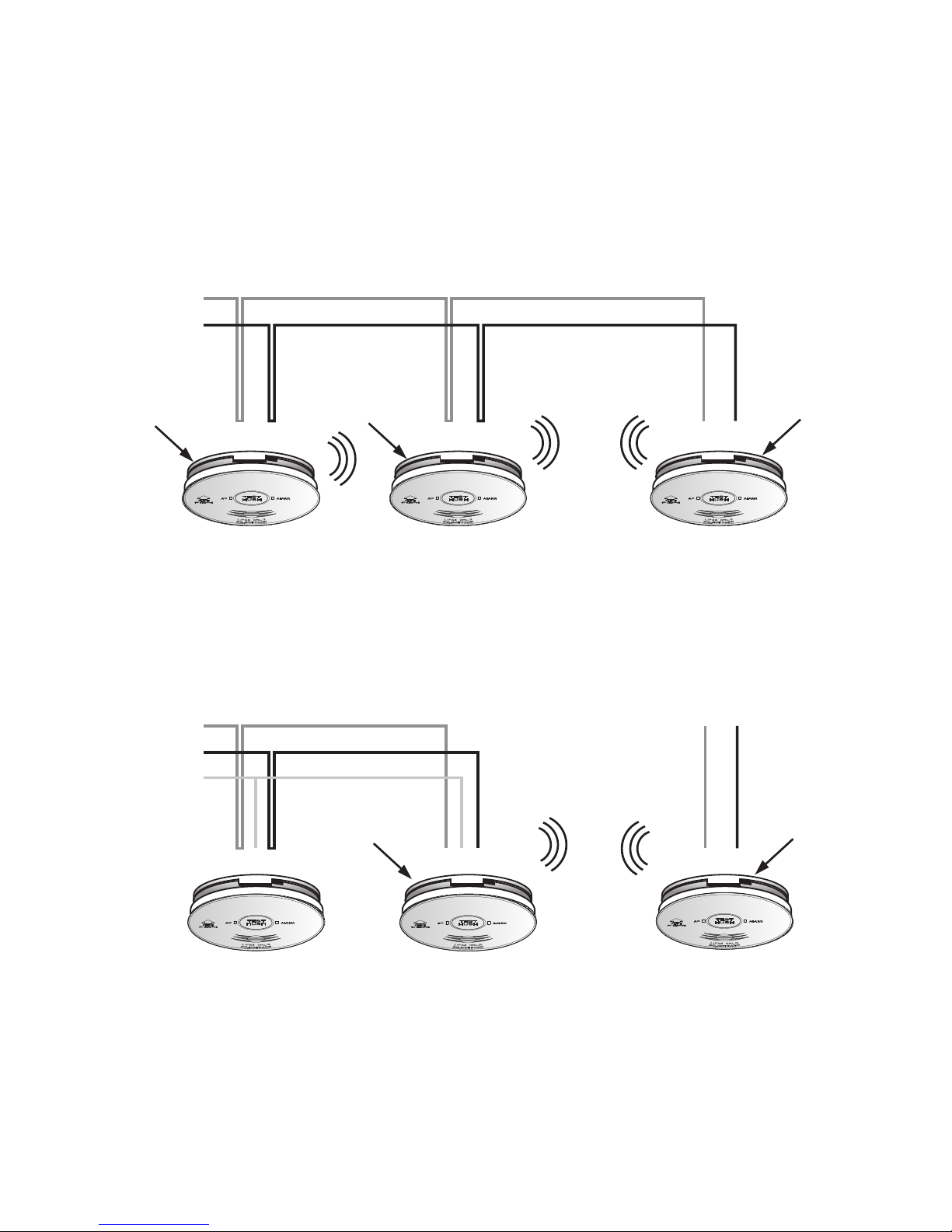
To connect all wireless bases use only the Active and Neutral lines, do not connect to
the SW terminal. See diagram below.
To expand an existing interconnected system, connect a wireless base to one alarm of the hardwired
system and then additional wireless base at each new location. DO NOT HARDWIRE THE SW
TERMINAL OF TWO ALARMS WITH WIRELESS BASE TOGETHER.
NOTE: Smoke alarms can be replaced without replacing the wireless base.
Active
Neutral
House Cabling
Wireless
baseplate
Wireless
baseplate
Wireless
baseplate
Active
Active Active
Neutral
House Cabling
Neutral
Neutral
Switch (SW)*
House Cabling
Wireless
baseplate
Wireless
baseplate
Wireless
baseplate
Wireless
baseplate
Wireless
baseplate
Page 14

11
5. Operating, Testing and Alarm Characteristics
OPERATION: The smoke alarm is operating once the alarm is activated (see Section 2) and testing is
complete. When products of combustion are sensed, the unit sounds a loud 85db pulsating alarm until
the air is cleared. If there is any question as to the cause of the alarm, it should be assumed that the
alarm is due to an actual fire and the dwelling should be evacuated immediately.
TESTING: Test by pushing the TEST button on the smoke alarm. If the unit is interlinked to other
devices in the network, all other alarms will sound. A short delay may happen before the alarms
activate. Pushing the button will sound the alarm if the electronic circuitry, horn, and battery are
working. If no alarm sounds, the unit has a defective battery or other failure, and should be replaced
with a new alarm. If RF interlinked to other wireless smoke alarms in the same network, all smoke
alarms will sound. It may take a few seconds for other interlinked units to alarm.
WARNING: DO NOT USE AN OPEN FLAME TO TEST YOUR ALARM, YOU COULD DAMAGE
THE ALARM OR IGNITE COMBUSTIBLE MATERIALS AND START A STRUCTURE FIRE. USE
SMOKE TESTER LIFLT711 TO EFFECTIVE TEST THE OPTICAL CHAMBER.
NOTE: MONTHLY TESTING IS RECOMMENDED.
LOCATE FUNCTION: If smoke alarms are interlinked in a network, if one smoke alarm activates
(initiating unit) other units will activate. It is possible to identify the initiating smoke alarm using the
locate function. For interlinked network of smoke alarms with WMB2 only, only by pressing the HUSH
button on the initiating smoke alarm will hush all the smoke alarms in the network.
If LIFESAVER LIF10YPEW smoke alarms are interlinked in the same network, pressing the HUSH button
on any non-initiating LIF10YPEW smoke alarm will silence all smoke alarms EXCEPT for the initiating
smoke alarm for 2 minutes. The LOCATE feature can be used repeatedly to find the initiating alarm or
until the smoke has cleared.
Page 15
12
6. Cleaning Your Alarm
YOUR ALARM SHOULD BE CLEANED AT LEAST ONCE A YEAR.
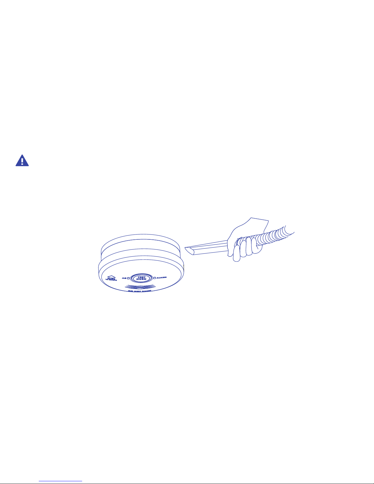
You can clean the interior of your alarm (sensing chamber) by using compressed air or a vacuum
cleaner hose and blowing or vacuuming through the openings around the perimeter of the alarm.
The outside of the alarm can be wiped with a damp cloth.
After cleaning, reinstall your alarm and test your alarm by using the button. If cleaning does not restore
the alarm to normal operation the alarm should be replaced.
WARNING : Reinstall the Alarm as soon as possible to ensure continuous protection.
Page 16

13
7. Good Safety Habits
DEVELOP AND PRACTICE A PLAN OF ESCAPE
• Install and maintain Fire extinguishers on every level of the home and in the kitchen, basement
and garage. Know how to use a fire extinguisher prior to an emergency.
• Make a floor plan indicating all doors and windows and at least two (2) escape routes from each
room. Second story windows may need a rope or chain ladder.
•
Have a family meeting and discuss your escape plan, showing everyone what to do in case of fire.
• Determine a place outside your home where you all can meet if a fire occurs.
• Familiarize everyone with the sound of the smoke alarm and train them to leave your home
when they hear it.
• Practice a fire drill at least every six months, including fire drills at night. Ensure that small
children hear the alarm and wake when it sounds. They must wake up in order to execute the
escape plan. Practice allows all occupants to test your plan before an emergency. You may not
be able to reach your children. It is important they know what to do.
RECOMMENDATIONS
Smoke Detection - Are More Smoke Alarms Desirable? The required number of smoke alarms might
not provide reliable early warning protection for those areas separated by a door from the areas
protected by the required smoke alarms. For this reason, it is recommended that the householder
consider the use of additional smoke alarms for those areas for increased protection. The additional
areas include the basement, bedrooms, dining room, utility room, and hallways not protected by the
required smoke alarms. The installation of the smoke alarms in the kitchen, attic (or unfinished), or
garage is normally not recommended, as these locations occasionally experience conditions that can
result in improper operation.
Page 17

14
8. Limitations Of Smoke Alarms
WARNING: PLEASE READ CAREFULLY AND THOROUGHLY.
• Life safety from fire in residential occupancies is based primarily on early notification to
occupants of the need to escape, followed by the appropriate actions by those occupants.
Fire warning systems for dwelling units are capable of protecting about half of the occupants
in potentially fatal fires. Victims are often too old or young, or physically or mentally impaired
such that they cannot escape even when warned early enough that escape should be possible.
For these people, other strategies such as protection-in-place or assisted escape or rescue are
necessary.
• Smoke alarms must be tested regularly to make sure the batteries and the alarm circuits are in
good operating condition.
• Smoke alarms cannot provide an alarm if smoke does not reach the alarm. Therefore, smoke
alarms may not sense fires starting in chimneys, walls, on roofs, on the other side of a closed
door or on a different floor.
• If the alarm is located outside the bedroom or on a different floor, it may not wake up a sound
sleeper.
• The use of alcohol or drugs may also impair one’s ability to hear the smoke alarm. For maximum
protection, a smoke alarm should be installed in each sleeping area on every level of a home.
• Although smoke alarms can help save lives by providing an early warning of a fire, they are not
a substitute for an insurance policy. Home owners and renters should have adequate insurance
to protect their lives and property.
Page 18

15
9. Warranty and Liability
1. PSA Products Pty Ltd (ABN: 99 076 468 703) of 17 Millicent Street, Burwood 3125 Victoria,
Australia warrants this product for a period of five (5) years from the date of purchase, as
reflected on the Authorised Reseller’s or Distributor’ invoice / receipt provided to you. PSA
Products Pty Ltd will repair or replace the product (at the option of PSA Products) due to any
manufacturing defect, at the cost of PSA Products Pty Ltd (excluding any labour costs relating to
removal or re-installation of product, and transport costs).
2. This warranty shall not apply to the product if it has been damaged, modified, abused or altered
after the date of purchase, or if it fails to operate due to improper maintenance.
3. To the extent permitted by law, the liability of PSA Products Pty Ltd arising from the sale or under
the terms of this limited warranty shall not in any case exceed the cost of replacement and subject
to this clause. In no case shall PSA Products Pty Ltd be liable for consequential loss or damages
resulting from the failure of the product or breach of this, or: Any other warranty, express or
implied, loss or damage caused by failure to abide by the instructions supplied in the leaflets.
4. To the extent permitted by law, PSA Products Pty Ltd., makes no warranty, expressed or implied,
written or oral, including that of merchantability or fitness for any particular purpose, with respect
to the consumer replaceable battery if any. A product with non-serviceable built-in battery is
covered under warranty of the product as per point 9.1.
5. This warranty is provided in addition to other rights and remedies you have under law: Our goods
come with guarantees that cannot be excluded under the Australian Consumer Law. You are
entitled to a replacement or refund for a major failure and compensation for any other reasonably
foreseeable loss or damage. You are also entitled to have the goods repaired or replaced if the
goods. fail to be of acceptable quality and the failure does not amount to a major failure. What
constitutes a major failure is set out in the Australian Consumer Law.
6 To make a claim under warranty, take the product (with a proof of purchase) to the store
where you purchased the product or contact PSA Products Pty Ltd. Phone (03) 9888 9889. or
Email: [email protected] with details, proof of purchase or expense claim in writing.
Page 19

16
10. Product warranty registration
Thank you for purchasing and installing the most trusted brand in fire, security and intercoms.
To ensure you receive excellent after-sale product service we encourage you to register your products.
There are a few important reasons to register your product:
1. It will ensure your investment is protected in case it is damaged or broken and we can effectively
carry out any warranty claims.
2. Registration will also allow us to contact you in an unlikely event of product safety notification
required under Consumer Product Safety Act.
3. Registration will also help us improve our product design to meet your needs.
Register at: http://www.psaproducts.com.au/register-product/
Register this product for warranty to ensure fast and effective service.
Otherwise, please retain this warranty section and complete the details below. When you claim
Warranty for the product please present this section together with the faulty product.
Model:_______________________ Serial Number: __________________________
Date Of Purchase/ Installation:_________________________ Invoice No: _____________________
Installed By:_________________________________________________________________________
___________________________________________________________________________________
Owner’s Details::_____________________________________________________________________
___________________________________________________________________________________
Smoke alarm has an expected service life of 10 years under normal conditions.
We recommend that you should replace the smoke alarm after 10 years from
installation date to ensure normal operation.
Page 20
17
DEAR INSTALLER:
PLEASE LEAVE THIS MANUAL FOR THE OWNER.
THANK YOU FOR CHOOSING THIS SMOKE ALARM.
Another Quality Product By:
PSA Products Pty Ltd
17 Millicent Street, Burwood, Victoria 3125
Ph: 1300 PSA PRODUCTS (1300 772 776)
Fax: (03) 9888 9993
Email:[email protected]
Webite:www.psaproducts.com.au
 Loading...