

Page 1
ProxxonTools.com
90
8
0
70
60
5
0
4
0
30
20
1
0
0
1
0
20
30
4
0
5
0
60
70
8
0
9
0
m
a
x
.
Z
ustell
u
ng
mm
B
r
ei
t
e
B
u
c
he
E
r
le
Pa
ppel
Ba
l
s
a
20
0
,
5
0
,
8
0
,
8
0
,
8
4
0
0
,
3
0
,
6
0
,
8
0
,
8
60
0
,
2
0
,
2
0
,
3
0
,
8
8
0
0
,
1
0
,
1
0
,
2
0
,
6
U
=
230
V~
5
0/60
H
z
P
=
200
W
KB
15
n
M
e
ss
e
rw
elle
=
6
.
000/
min
B
r
ei
t
e
m
a
x
=
8
0
mm
MT
300
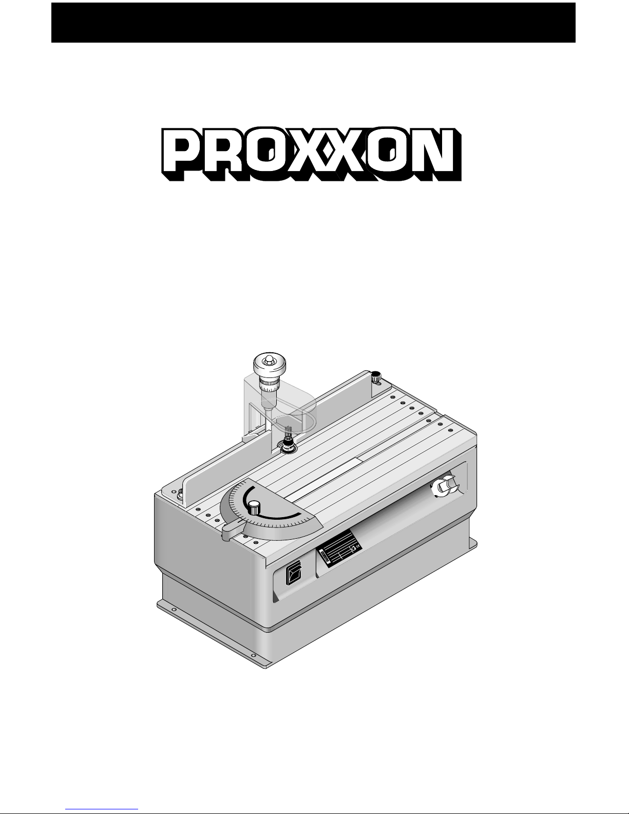
MICRO Shaper MT 300
Manual
Page 2
- 3 -
9
0
8
0
70
60
5
0
4
0
30
20
1
0
0
1
0
20
30
4
0
5
0
60
70
8
0
9
0
4
7
3
9
1
5
13
2
12
Fig 1
m
a
x
.
Z
ust
ell
u
ng
mm
B
r
ei
t
e
B
u
c
he
E
r
le
Pa
ppel
Ba
l
s
a
20
0
,
5
0
,
8
0
,
8
0
,
8
4
0
0
,
3
0
,
6
0
,
8
0
,
8
60
0
,
2
0
,
2
0
,
3
0
,
8
8
0
0
,
1
0
,
1
0
,
2
0
,
6
U=
230
V~
5
0/60
H
z
P
=
200
W
KB
15
n
M
e
ss
e
rw
elle
=
6
.
000/
min
B
r
ei
t
e
m
a
x
=
8
0
mm
MT
300
6
14
8
11
10
m
a
x
.
Z
ust
ell
u
ng
mm
B
r
ei
t
e
B
u
c
he
E
r
le
Pa
ppel
Ba
l
s
a
20
0
,
5
0
,
8
0
,
8
0
,
8
4
0
0
,
3
0
,
6
0
,
8
0
,
8
60
0
,
2
0
,
2
0
,
3
0
,
8
8
0
0
,
1
0
,
1
0
,
2
0
,
6
U=
230
V~
5
0/60
H
z
P
=
200
W
KB
15
n
M
e
ss
e
rw
elle
=
6
.
000/
min
B
r
ei
t
e
m
a
x
=
8
0
mm
MT
300
3
2
1
2
4
1
2
m
a
x
.
Z
ust
ell
u
ng
mm
B
r
ei
t
e
B
u
c
he
E
r
le
Pa
ppel
Ba
l
s
a
20
0
,
5
0
,
8
0
,
8
0
,
8
4
0
0
,
3
0
,
6
0
,
8
0
,
8
60
0
,
2
0
,
2
0
,
3
0
,
8
8
0
0
,
1
0
,
1
0
,
2
0
,
6
U=
230
V~
5
0/60
H
z
P
=
200
W
KB
15
n
M
e
ss
e
rw
elle
=
6
.
000/
min
B
r
ei
t
e
m
a
x
=
8
0
mm
MT
300
m
a
x
.
Z
ust
ell
u
ng
mm
B
r
ei
t
e
B
u
c
he
E
r
le
Pa
ppel
Ba
l
s
a
20
0
,
5
0
,
8
0
,
8
0
,
8
4
0
0
,
3
0
,
6
0
,
8
0
,
8
60
0
,
2
0
,
2
0
,
3
0
,
8
8
0
0
,
1
0
,
1
0
,
2
0
,
6
U=
230
V~
5
0/60
H
z
P
=
200
W
KB
15
n
M
e
ss
e
rw
elle
=
6
.
000/
min
B
r
ei
t
e
m
a
x
=
8
0
mm
MT
300
m
a
x
.
Z
ust
ell
u
ng
mm
B
r
ei
t
e
B
u
c
he
E
r
le
Pa
ppel
Ba
l
s
a
20
0
,
5
0
,
8
0
,
8
0
,
8
4
0
0
,
3
0
,
6
0
,
8
0
,
8
60
0
,
2
0
,
2
0
,
3
0
,
8
8
0
0
,
1
0
,
1
0
,
2
0
,
6
U=
230
V~
5
0/60
H
z
P
=
200
W
KB
15
n
M
e
ss
e
rw
elle
=
6
.
000/
min
B
r
ei
t
e
m
a
x
=
8
0
mm
MT
300
1
2
3
Fig. 1 Fig. 1
Fig. 2
Fig. 4
Fig. 7a Fig. 7b Fig. 7c
Fig. 6
Fig. 3a Fig. 3b
Fig 5a
2 1
Fig. 5b
Fig. 5a
Page 3

- 4 -
Operating Instructions
MT 300
Instructions for the use of the MICRO Shaper
MT 300:
Dear Customer,
In order to be able to operate the shaper safely and
correctly, please carefully read the following safety and
operating instructions prior to use.
This instruction manual covers:
• safety regulations
• operation and maintenance
• spare parts list
Please read carefully and become familiar with this
entire instructions manual. Learn the tool´s applications,
limitations and possible hazards.
Using this instruction manual will
• make it easier for you to get used to the machine,
• help prevent faults occurring due to improper use and
• increase the service life of your machine.
Keep this instruction manual in an easily accessible
place. Only operate this machine if you are qualified to
do so and follow the guidelines in this instruction
manual.
PROXXON does not accept responsibility for the safe
functioning of the machine
• if it is handled in a manner which constitutes improper
use,
• if it is used for other purposes which are not specified
in the instruction manual,
• if the safety regulations are not observed.
Warranty claims are invalid if
• the machine is incorrectly operated,
• the machine has not been sufficiently maintained.
In the interests of your safety, please always observe
the safety regulations.
Only use genuine PROXXON spare parts.
We reserve the right to make further alterations for the
purpose of technical progress.
We wish you every success with your machine.
Safety instructions
1. KEEP GUARDS IN PLACE and in working order.
2. REMOVE ADJUSTING KEYS AND WRENCHES.
Form habit of checking to see that keys and
adjusting wrenches are removed from tool before
turning it on.
3. KEEP WORK AREA CLEAN. Cluttered areas and
benches invite accidents.
4. DON’T USE IN DANGEROUS ENVIRONMENT.
Don’t use power tools in damp or wet locations, or
expose them to rain. Keep work area well lighted.
5. KEEP CHILDREN AWAY. All visitors should be kept
safe distance from work area.
6. MAKE WORKSHOP KID PROOF with padlocks,
master switches, or by removing starter keys.
7. DON’T FORCE TOOL. It will do the job better and
safer at the rate for which it was designed.
8. USE RIGHT TOOL. Don’t force tool or attachment
to do a job for which it was not designed.
9. USE PROPER EXTENSION CORD. Make sure
your extension cord is in good condition. When
using an extension cord, be sure to use one heavy
enough to carry the current your product will draw.
An undersized cord will cause a drop in line voltage
resulting in loss of power and overheating. Table 1
shows the correct size to use depending on cord
length and nameplate ampere rating. If in doubt,
use the next heavier gage. The smaller the gage
number, the heavier the cord.
10. WEAR PROPER APPAREL. Do not wear loose
clothing, gloves, neckties, rings, bracelets, or other
jewelry which may get caught in moving parts.
Nonslip footwear is recommended. Wear protective
hair covering to contain long hair.
Exception: The reference to gloves may be omitted
from the instructions for a grinder.
11. ALWAYS USE SAFETY GLASSES. Also use face or
dust mask if cutting operation is dusty. Everyday
eyeglasses only have impact resistant lenses, they
are NOT safety glasses.
12. SECURE WORK. Use clamps or a vise to hold work
when practical. It’s safer than using your hand and it
frees both hands to operate tool.
13. DON’T OVERREACH. Keep proper footing and
balance at all times.
14. MAINTAIN TOOLS WITH CARE. Keep tools sharp
and clean for best and safest performance. Follow
instructions for lubricating and changing
accessories.
15. DISCONNECT TOOLS before servicing; when
changing accessories, such as blades, bits, cutters,
and the like.
16. REDUCE THE RISK OF UNINTENTIONAL
STARTING. Make sure switch is in off position
before plugging in.
17. USE RECOMMENDED ACCESSORIES. Consult
the owner’s manual for recommended accessories.
The use of improper accessories may cause risk of
injury to persons.
18. NEVER STAND ON TOOL. Serious injury could
occur if the tool is tipped or if the cutting tool is
unintentionally contacted.
Page 4

- 5 -
19. CHECK DAMAGED PARTS. Before further use of
the tool, a guard or other part that is damaged
should be carefully checked to determine that it will
operate properly and perform its intended function –
check for alignment of moving parts, binding of
moving parts, breakage of parts, mounting, and any
other conditions that may affect its operation.
A guard or other part that is damaged should be
properly repaired or replaced.
20. DIRECTION OF FEED. Feed work into a blade or
cutter against the direction of rotation of the blade or
cutter only.
21. NEVER LEAVE TOOL RUNNING UNATTENDED.
TURN POWER OFF. Don’t leave tool until it comes
to a complete stop.
22. WHEN SERVICING USE ONLY IDENTICAL
REPLACEMENT PARTS.
23. TO REDUCE THE RISK OF ELECTRIC SHOCK,
THIS EQUIPMENT HAS A POLARIZED PLUG.
(One blade is wider than the other). This plug will fit
in a polarized outlet only one way. If the plug does
not fit fully in the outlet, reverse the plug. If it still
does not fit, contact a qualified electrician to install
the proper outlet. Do not change the plug in any
way.
Table 1:
Minimum gage for cord:
Total length of
cord in feet 25 ft 50 ft 100 ft 150 ft
AWG: 18 16 16 14
Additional safety instructions:
• Ensure the workplace is tidy.
• Check the unit for damage before use (connection
cable, protective devices, etc.), have defective parts
replaced by qualified personnel.
• This unit corresponds to the pertinent safety
regulations. Repairs (e.g., replacement of the power
supply lead) may only be performed by a qualified
electrician
• Never work without the safety equipment fitted.
• Do not use electrical power tools in the rain, in damp
surroundings or in the vicinity of flammable liquids or
gases.
• Only use the tool when the handle is dry and free from
grease.
• Avoid contact with earthed components, e.g., pipes,
radiators, ovens and refrigerators.
• Protect the connection lead from heat and sharp
edges and route it so it cannot be damaged.
• Do not remove the plug from the socket by pulling on
the cable.
• Do not pick up the unit by the cable.
• Keep children and third parties away from the
workplace.
• Keep tools in childsafe locations when not in use.
• Do not overload the tool.
• Do not use the tool to perform operations for which it is
not suitable.
• Replace blunt tools in good time.
• Visually inspect application tools to ensure they are in
good working order and suitable for the task prior to
setting up the job.
• Fasten tools securely.
• Clean the unit thoroughly following all work.
• Disconnect the plug from the power supply when the
unit is not in use, before performing maintenance, tool
replacement or repair work.
• Only plug the unit in when the unit is switched off.
• Always wear protective goggles (danger of tool
breakage).
• If necessary, wear a protective dust mask.
• Only use appropriate working clothes (no loose
sleeves, ties, jewelry).
• Wear a hair net if you have long hair.
• Only use accessories and spare parts recommended
by PROXXON.
• Observe the max. permitted rotational speed.
• If necessary, use dust extract equipment.
• Do not use the tool when you are tired or under the
influence of alcohol.
• Keep fingers away from rotating or fast moving tools
(saws, etc.).
• Keep the operation instructions in a safe place.
Additional safety instructions for shapers:
WARNING
For Your Own Safety Read Instruction Manual Before
Operating Shaper!
• Always wear eye protection.
• Feed workpiece against rotation of cutter.
• Do not use awkward hand positions.
• Keep fingers away from revolving cutter – use fixtures
when necessary.
• Use overhead guard when adjustable fence is not in
place.
• Fix the machine to a solid base.
• Always wear ear protection.
Page 5

- 6 -
Description of the machine
The MT 300 table milling machine is ideal for shaping,
grooving, chamfering, edging and taking out. With the
milling cutter running at 30,000 rpm, clean and precise
results with rapid waste removal are guaranteed. The
cutter height can be adjusted for a wide range of tasks.
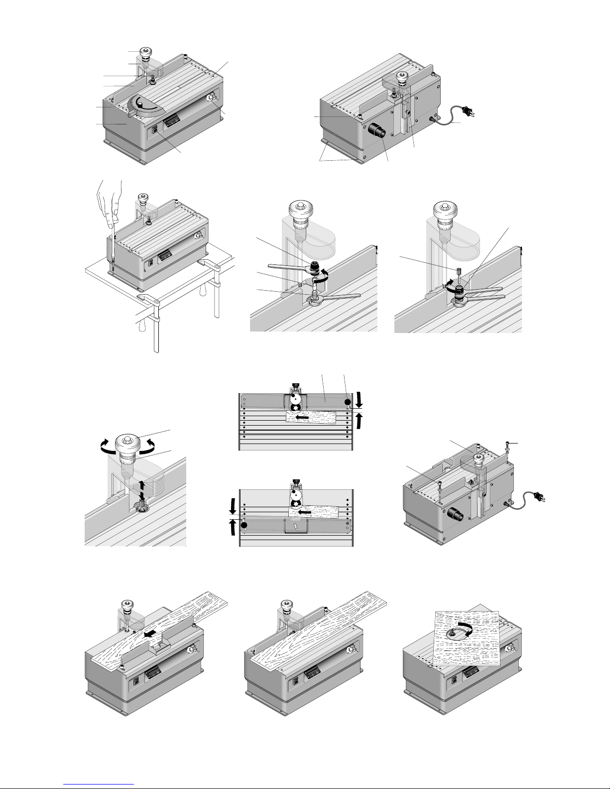
Overall view (fig. 1):
1. Housing
2. Table
3. Fence
4. Hand wheel for milling cutter height adjustment
5. On-Off switch
6. Fence clamping screw
7. Cutter shield (Guard)
8. Clamping screw for cutter shield
9. Milling cutter
10. Fixing holes
11. Vacuum cleaner connection
12. Spanner holder
13. Angle stop
14. Supply cable
Included in delivery:
1 pc. MICRO Shaper
2 pc. Spanners
1 pc. Extractor connection
1 pc. Angle stop
3 pc. Collets
Technical data:
Voltage: 110-120 V, 50/60 Hz, ~
Power: 1/8 hp (100 W) 10 min
Cutter speed: 30000 rpm
Table Size: 111/2” x 6” (293 x 150 mm)
Weight: approx. 4,4 lb (2.0 kg)
Milling cutter
shaft diameter: up to 1/8” (3.2 mm)
Noise level: 91 dB(A)
Work piece
height/thickness: 1,5” (40 mm)
Double Insulated
For indoor use
Operation
Before milling
Fixing the shaper
(see also fig. 2)
Before starting work, fasten the shaper to a solid
wooden base with suitable screws. Fixing holes are
provided for this purpose in the base of the housing.
The wooden base can then, for example, be fixed to a
bench by means of screw clamps.
Fitting and changing the milling cutter:
Note!
When carrying out any of the work described below, it is
appropriate to raise the adjustable cutter shield (see fig.
1, item 7) to its maximum height. Disconnect by pulling
the plug!
Fitting the milling cutter:
Note!
Ensure that the cutter is suitable for running speeds up
to 30,000 rpm.
1. With one of the C-spanners provided, block the
cutter shaft 1 (see fig. 3a). With the other, unscrew
and remove the clamping nut, 2.
2. Insert a collet of the correct size in the mouth of the
shaft and screw the clamping nut back on but do not
tighten it.
3. Insert the selected milling cutter, 4, (fig. 3b).
4. Tighten the clamping nut, as shown in fig. 3b.
Changing the milling cutter:
1. As shown in fig. 3b, loosen but do not remove the
clamping nut.
2. Remove the milling cutter, 4.
3. Insert a new milling cutter.
4. Re-tighten the clamping nut.
Note!
The diameter of the cutter shaft and the inner diameter
of the collet must match! If this requires that to change
the collet, proceed as described under “Fitting the
milling cutter” above.
Cutter height adjustment
Before milling, the cutter height must be set. To this
end, turn the hand wheel, 1, (fig. 4). Turn clockwise to
raise the cutter, turn anti-clockwise to lower. Note that
one full turn of the hand wheel corresponds to an
adjustment of 1 mm (0,04 inch). With the adjustable
dial, 2, the required cutter height can be set exactly.
Adjusting the fence (figs. 5 and 6)
As shown in fig. 5a, the fence is suitably positioned for
bevelling or grooving the edges of boards.
1. Loosen the knurled screw, 1.
2. Swing the fence, 2, to obtain the desired cutting
depth.
3. Re-tighten the knurled screw.
If grooves are to be cut in the surface of boards or
similar items, the fence can be positioned as shown in
fig. 5b).
Page 6

- 7 -
Proceed as follows:
Note!
For this purpose, it is necessary to remove the cutter
shield (fig. 1, item 7). In this case, loosen the knurled
screw, 8, (fig. 1) and lift off the shield. When re-
mounting the shield, ensure that the hexagonal tip on
the shield engages correctly with the hexagonal socket
of the milling cutter carriage.
1. Completely remove the knurled screw and the Allen
screw, 1 and 2, (fig. 6), including the corresponding
washers and sleeves.
2. Roughly estimate the distance from the milling
cutter. The fence can then be fixed in the position
shown as item 3 by inserting the screws in the
appropriate threaded holes in the milling table. Do
not forget the sleeves and washers. Do not
immediately tighten the knurled screw.
3. The fine setting can now be carried out as
described under “Adjusting the fence” above.
Angle stop (fig. 1, item 13)
This can be fitted in the groove provided and slid to the
desired position. To adjust, loosen the knurled nut and
rotate the plastic part
Milling
Fig. 7 shows some applications for the use with our
MICRO-shaper.
Note!
Wear ear defenders!
Danger of injury:
Always work with the the milling cutter shield!
If you have to dismount the cutter protection for an
application like shown in Fig. 7 c, be extremely careful!
Danger of injury!
Note!
For use in schools (children over 14 years age) the
knurled screw of the milling cutter shield must be
replaced by a screw requiring a tool and the cutter
shield must be set at 5 mm (0,2 inch).
The cutter shield must be set so that it covers the cutter
immediately above the work piece. Exercise particular care
when milling workpieces over 5 mm (0,2 inch) thickness.
Keep your fingers clear of the rotating cutter. The
workpiece may only be so long and wide as can be
properly supported and fed on the milling table. The
cutting depth should never exceed 0.04 inch. For
milling, the work piece is slid along the fence. It must be
ensured that the cutting depth and feed rate are not
excessive! Cutting too deeply and too high a feed rate
lead to poor results and load the mechanism
unnecessarily. It is preferable to make a number of
milling passes with small adjustments of the fence and/
or the cutter height.
Note!
It is recommended that the dust extraction should
always be used. A rubber extractor connection is
located on the rear of the machine. Vacuum cleaner can
be readily connected here.
Care and maintenance
Note!
Defective parts should be changed by a qualified
technician.
Note!
Before carrying out repairs, pull the electrical plug. The
shaper requires little maintenance. To prolong its life,
you should clean the machine after each use with
compressed air or a soft cloth. Always use the dust
extractor.
Maintenance
Important
Pull out the mains plug prior to commencing all
maintenance and repair work.
Warning!
Turn switch OFF and always remove plug from power
source before making any adjustments or repairs.
If any part is missing or damaged, do not plug the tool in
until the missing or damaged part is replaced, and
assembly is complete. To avoid electrical shock, use
only identical replacement parts when servicing the tool.
Warning!
To avoid fire or toxic reaction, never use gasoline,
naphtha, acetone, lacquer thinner, or similar highly
volatile solvents to clean the MICRO Shaper.
Do not allow brake fluids, gasoline, or penetrating oils to
come in contact with the plastic parts. They contain
chemicals that can damage or destroy plastics!
All electrical or mechanical repairs should be done only
by qualified service technicians.
When servicing use only PROXXON replacement parts.
Use of any other parts may create a hazard or cause
product damage.
Any attempt to repair or replace electrical parts on this
tool may create a hazard unless repair is done by a
qualified service technician.
Repair service is available at your PROXXON service
center
(You find the address at address at the back of this
manual).
 Loading...