

Page 1
DH 40
Manual
Page 2
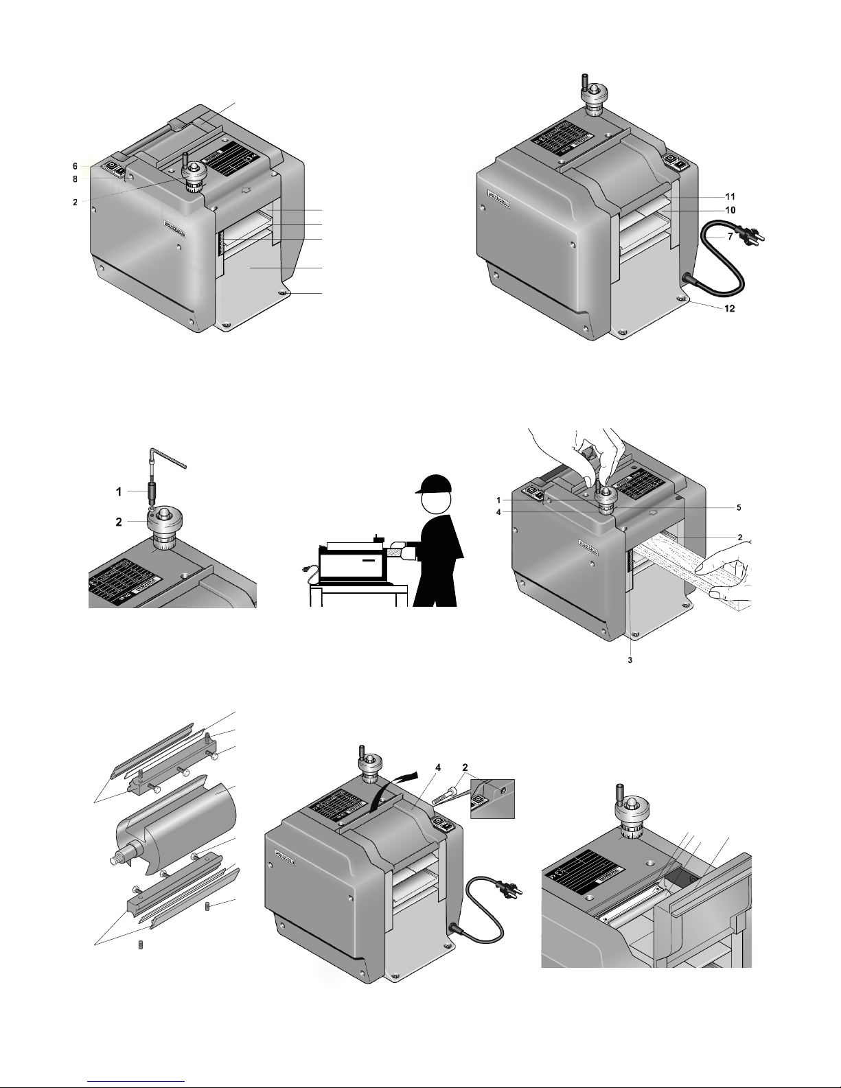
Fig. 1a
Fig. 1b
Fig. 2
Fig. 4
Fig. 3
Fig. 5 Fig. 6
7
6
6
9
9
7
8
8
5
- 3-
max. Zustellung mm
Breite Buche Erle Pappel Balsa
20 0,5 0,8 0,8 0,8
40 0,3 0,6 0,8 0,8
60 0,2 0,2 0,3 0,8
80 0,1 0,1 0,2 0,6
U = 230V~
50/60 Hz
P = 200 W KB 15
n
Messerwelle
= 6.000/min
Breite
max
= 80 mm
DH 40
3
9
6
8
2
4
5
1
12
3
P 0 W KB
max
Breite
m
6.0
n
P = 200 W KB 15
= 23
/60 Hz
m
0,20,10,180
0,30,2
60
0,80,80,60,340
Erle
uche
Breite
max. Zustellung mm
9
4
5
1
12
12
4
5
7
6
max. Zustellung mm
Breite Buche Erle Pappel Balsa
20 0,5 0,8 0,8 0,8
40 0,3 0,6 0,8 0,8
60 0,2 0,2 0,3 0,8
80 0,1 0,1 0,2 0,6
U = 230V~
50/60 Hz
P = 200 W KB 15
n
Messerwelle
= 6.000/min
Breite
max
= 80 mm
DH 40
4
7
6
4
DH 40
= 80 mm
= 6000/min
max
Messerwelle
Breite
6.0
mm
Mes
ite
n
n
P = 200 W KB 15
23
/6
U = 230V~
50/6
6 Hz
20
0V~
60 H
0,6
0,2
0,1
0,1
80
0,8
0,3
0,20,260
0,8
0,8
0,60,340
0,8
Balsa
0,8
Pappel
0,8
Erle
0,5
Buche
0
0
mm
mm
Bu
20
Z
Breite
max. Zustellung m
20
454
Fig. 2a
Page 3

Translation of the
Original Operating Instructions
Thickness planer DH 40
Contents:
Foreword ....................................................................10
Safety instructions ......................................................10
Description of the machine ..........................................11
Scope of supply ..........................................................12
Technical data DH 40..............................................12
Installation and commissioning ..................................12
Planing ........................................................................13
Repair and maintenance ............................................13
Changing the cutters ..............................................13
Adjusting the cutters ..............................................14
Cleaning ......................................................................14
Lubrication ..............................................................15
Spare parts lists ..........................................................78
Foreword
The use of this manual
• makes it easier to get to know the equipment.
• prevents faults caused by incorrect operation and
• increases the life of your equipment.
Always keep this manual ready to hand.
Only operate this equipment if you have a thorough
knowledge of it and in accordance with the manual.
PROXXON shall not be liable for the safe operation of the
equipment in the case of:
• handling, which is not in accordance with normal use,
• other purposes, which are not mentioned in the
manual,
• non-observance of the safety regulations.
You have no claim under the warranty in the case of:
• operator errors
• lack of maintenance
• use of non-PROXXON spare parts
For your own safety, please be sure to observe the safety regulations.
Use only original PROXXON spare parts.
We reserve the right to make improvements in the interest of technical progress. We wish you every success
with the equipment.
Safety instructions
Avoid disorder in the working area.
Disorder in the working area always means an increased
risk of accidents. Remember to clean wood shavings
from the workplace every now and then even during operation.
Fix the unit on a firm foundation so that it is level and
secure.
Make sure in all cases that the unit cannot fall or topple,
especially during operation. Holes, which can be used to
bolt the planer to the foundations, are provided in the feet
for this purpose.
Check the unit for damage before every use.
Please check the planing machine each time before using, particularly the cutting tools, the safety devices and
the connecting cable and plug. Please note: Defective
parts, especially damaged safety devices, may only be
changed by a specialist or by the PROXXON Customer
Service Department.
Use only original PROXXON spare parts.
Never interfere with the planing machine.
Do not change anything on the machine and do not carry out any modifications. This could be detrimental to mechanical and electrical safety; in particular, there is a risk
of electric shock and your safety could be further prejudiced. This can result in injury and material damage.
Never work without the safety equipment provided.
Make sure that all the housing covers of the planer are
closed during operation in all cases and that the kickback
protection device is working properly. After actuation, the
kickback fingers must drop back into their starting position of their own accord, the edges of the points must be
sharp and the fingers must not be deformed.
Pay attention to the surrounding conditions.
Use the planer only in dry environments and never in the
vicinity of combustible liquids or gases.
Make sure that there is adequate lighting.
Use a dust mask and only use the planing machine in
well ventilated rooms.
The dust from some of the types of wood to be machined
could be damaging to health if inhaled. Therefore take the
necessary precautions and wear a dust mask.
Use protective goggles.
Inspect the workplace carefully before planing.
Check the workpiece that you want to plane for possible
inclusions such as nails, screws, stones etc and remove
these.
Metal parts in particular that are embedded in the work
piece can damage the shafts and knives in your thicknesser and render it useless. The work piece might possibly splinter, Caution: Risk of injury! The slide face on the
planing table can become scratched and thus lead to impaired function.
- 10 -
GB
Page 4

Touching that the cutter shaft with a metal object can
cause serious damage.
Use a "pusher" when planing extremely short workpieces.
To avoid injuries due to the kickback device or the cutter
shaft, please use a wooden "pusher" to feed the workpiece into the planer.
Wear ear defenders.
The sound pressure level when working with the planing
machine can exceed 85 dB (A); therefore only work when
using ear defenders.
Wear suitable working clothes.
Do not wear loose-fitting clothing when working such as
ties or scarves, for example; they could catch in one of
the moving parts or the automatically moving workpiece
during operation and cause injury. If you have long hair,
where a hair net and remove jewellery.
Do not use damaged or deformed reversible cutters.
Please ensure that the reversible cutters in the planer
shaft are in perfect condition. Check these before each
use by visually inspecting for freedom from damage. Use
only Proxxon original spare parts when replacing.
Keep children and persons who are not involved
away from the working area.
Ensure that children and persons who are not involved
remain at a sufficiently safe distance. Young people under 16 years of age may only use the planer under expert
instruction and for the purposes of training. The planing
machine must be kept inaccessible to children when not
in use.
Do not overload your machine.
Naturally, you will only achieve optimum working results
within the power range for which the machine is designed. Therefore avoid too large a depth of cut; rather,
follow the recommendations for the correct depth of cut
on the table on the unit. Do not abuse your machine and
do not use it for work for which it is not intended.
Be mindful and alert at all times.
Watch the unit while working and act sensibly. Do not use
the machine when you cannot concentrate or are tired or
have drunk alcohol.
Treat the connecting cable with care.
Protect the cable from heat and sharp edges and lay it in
such a way that it cannot be damaged. Do not use the cable to pull the plug from the socket and do not lift the unit
by means of the cable. Pay attention to cleanliness: Protect the cable from grease and oil.
Pay attention to the shape of the work piece!
Extremely curved or otherwise very irregularly shaped
work pieces may not be planed! Possibly the contact to
the planing table may not be sufficient!
Always allow the work piece to "run through"!
Never (!) stop a work piece that is in the process of being pulled in – do not hold on to it, press against it, or use
any other type of force! Use only work pieces whose
cross section is suitable for your planing machine!
Please wear a dust mask!
Some types of wood or even varnish residues (or similar)
can generate harmful dusts during working. If you are unsure of the harmlessness of your planing material, please
wear a dust protection mask!
Provide roller tables for very long work pieces!
To avoid damage and dangerous situations, use roller tables when processing very long work pieces which must
be carefully placed in the push-in or push-out direction.
If the cable is damaged, the planing machine must be
stopped immediately and the cable replaced by a competent person without delay.
Clean the unit thoroughly after working.
Unplug from the mains.
Always unplug from the mains when not in use, before
carrying out maintenance, changing the tool, cleaning or
carrying out repair work. Cleaning also includes the removal of loose shavings or the vacuuming of dust.
Read the operating manual well before use and look
after it carefully.
Description of the machine
Key (Fig. 1):
1. Die-cast aluminium chassis
2. Hand wheel for height adjustment
3. Service flap
4. Planing table
5. Linear scale
6. On-Off switch
7. Mains cable
8. Locking screw
9. Infeed slot
10. Outfeed slot
11. Shavings discharge
12. Screw holes
The PROXXON DH 40 thickness planer is a unit for fine
planing work with a particularly uniform and smooth finish for hardwood and softwood workpieces with a cross
section of up to 80 mm wide and 40 mm high. The cutter
shaft used has 2 HSS reversible cutters for a particularly long service life. These can be replaced by means of
a generously sized service flap 3 (Fig. 1). The supporting
structure 1 is made of die-cast aluminium, which guarantees maximum stability. All parts have been carefully
- 11 -
Page 5

machined and thus guarantee maximum precision and
longevity.
The planer has an automatic feed unit. The workpiece is
therefore only pushed by hand into the infeed slot 9 for a
short distance. A knurled and spring-loaded roller then
draws the workpiece in, thus enabling even irregularly
shaped pieces of wood to be planed. After passing the
cutter shaft, the piece of wood is pushed out at the rear
by a rubber-coated roller through the outfeed slot 10.
The cutter shaft and the feed unit are driven by a powerful electric motor, which transmits its movement to the
rollers and the shaft by means of gear wheels and
toothed belt drives. The respective linear and rotational
speeds are exactly matched to one another.
The height of the planing table 4 and thus the planing
thickness can be conveniently and reliably adjusted by
means of the large hand wheel 2 on the top of the housing.
Caution!
The planer is equipped with a so-called re-start protection facility. If the supply is interrupted for a short time during operation, the planer will not re-start automatically for
safety reasons. However, in this case, the planer can be
started normally by means of the "on" switch.
Scope of supply
1 off Thickness planing machine DH 40
1 off Pin for height adjustment hand wheel
1 off Operating manual
Technical data DH 40:
Voltage: 230 Volt ⵑ,
50/60 Hz
Power: 200 Watt
KB 15 min
Max. pass-through height: 40 mm
Max. pass-through width: 80 mm
Length of planing table: 232 mm
Swept diameter of shaft: 48 mm
Planing cutter length: 82 mm
Cutters: 2-off HSS reversible
cutters
Planing shaft speed on no-load: 6000 rpm
Max. planing reduction: 0.8 mm
Feed speed: 4.8 m/min
Sound pressure level: ca. 85 dB(A)
Sound power level: ca. 98 dB(A)
Vibration: ≤ 2.5 m/s
2
General measuring uncertainty K=3 dB
Dimensions:
Length: 280 mm
Height: 232 mm
with hand wheel: 300 mm
Width: 225 mm
Weight: ca. 8 kg
For use in enclosed rooms only!
Please do not dispose off the machine!
Installation and commissioning
Caution!
Please check the thickness planer immediately for possible transit damage. Damage to the packaging may indicate incorrect handling during shipping. It is essential
that transit damage should be reported immediately to the
dealer or to the shipping company concerned.
Note:
The foundations for the erection of the planer must be
firm, clean and dry.
1. To erect the planer, remove the machine from the
packaging and place on a flat and level foundation.Ensure that the machine is standing safely and that it
cannot fall during operation.
2. Please note: The planer may only be operated if
screwed securely to the surface! The die-cast aluminium base of the device has 4 drill holes with a 6
mm diameter for this purpose. We recommend M6 or
M5 cheese-head screws or other appropriate screws.
3. Screw the pin 1 (Fig. 2) onto the hand wheel of the
planer using an Allen Key.
Caution:
Before plugging in the mains plug, please check whether
the information on the rating plate corresponds with the
characteristics of your local electricity supply.
4. Plug in the mains cable.
- 12 -
Page 6

Planing
Caution:
Always operate the thicknesser from the position as
shown in Fig. 2a so that you are always in optimal control of the work piece. Stand in front of the device while
working! Never work with your DH 40 from the side or
even from the back. Ensure sufficient stability while you
work!
Caution:
Never use your hand to reach into the infeed slot while
the planer is in operation! Risk of injury!
Caution:
Wear protective goggles.
Caution:
The service flap must always be closed during operation.
The planer is now ready for operation. The height of the
planing table 2 and thus the pass-through height and the
depth of cut (i.e. the "planing depth") can now be set on
the hand wheel 1 (Fig. 3). The position of the planing
table must, of course, first be set roughly to the thickness
of the workpiece. This can expediently be estimated by
means of the linear scale 3 at the side of the inlet opening. The value printed here gives the distance between
the tips of the planing cutters and the surface of the planing table. If this value is the same as the thickness of the
workpiece, the depth of cut (i.e. the "shaving thickness"
so to speak) is exactly "zero".
Note:
It is recommended that the opening be set rather "generously" and the workpiece run through a few times.
increasing the depth of cut a little each time by turning the
hand wheel to the left in order to obtain a feel for the correct height. When the planing cutter just comes into contact with the top edge of the workpiece while it is passing
through, then the depth of cut is zero.
The scale ring 4 on the hand wheel can now be set to ze-
ro. There is a mark 5 on the housing to assist with this.
The required depth of cut can now be set using the hand
wheel. One turn corresponds to one millimetre stroke of
the planing table, i.e. if it is required to make a reduction
of 0.5 millimetres, the hand wheel must be turned to the
left by half a turn. The exact value can be read off on the
scale ring.
Note:
Although your planer is a solid and robustly made machine, in spite of this it is primarily intended for fine and
precise working. Do not overload the planer by machining
harder types of wood with large depths of cut and a corresponding width of workpiece over a long period of time.
Please note:
When you have run the workpiece through and planed it
a few times and are approaching the required thickness,
it is recommended that the last passes be made with a
rather smaller depth of cut in the interests of a better surface quality.
If the workpiece is drawn in but comes to a stop after a
few centimetres, then the depth of cut has been set too
large. In this case, turn the hand wheel to the right to lower the planing table and thus reduce the depth of cut. The
workpiece will then be drawn in normally once more.
Then continue to plane until the required thickness is
achieved.
Note:
Make sure that no work pieces are inserted, which are
higher than 40 mm.
In this case, the workpiece will no longer be pushed
through by the draw-in roller in the planer and can become stuck in the kickback device, which normally prevents the workpiece from sliding back.
Note:
Depending on the amount of accumulated dust, we recommend cleaning the chip discharge channel (pos. 11,
Fig. 1) with a vacuum cleaner. Caution! Always switch off
the planer!
Repair and maintenance
Changing or reversing the planing cutters
The cutter shaft of your planer is equipped with 2 reversible cutters for the highest surface quality. Each of
the fitted planer cutters 6 (Fig. 4) has two blades (reversible cutters). When the first has become worn or
damaged, you can simply remove the cutter, reverse it
and use the other side. When this is no longer sharp
enough, then new cutters must be fitted. Remember always to reverse or replace the cutters in pairs.
You can obtain replacement cutters from your dealer.
Use only the spare knives intended for the machine!
Note:
Used planing cutters must not be reground. Please always replace or reverse them. Replace damaged planing cutters immediately.
Caution:
Please only handle the cutters with extreme care, as
these are very sharp. Risk of injury!
Caution:
When carrying out any repair and service work, it is essential that the mains plug be removed in order to prevent accidental starting of the planer.
- 13 -
Page 7

Risk of injury!
1. Unscrew the blocking screw 2 (fig. 5).
Caution:
Never operate the planing machine with parts of the
housing removed. Risk of injury!
To avoid injuries caused by sharp edges, in particular
knife edges, please wear appropriate protective gloves!
2. Open cover 4.
3. Turn the cutter shaft 5 (Fig. 4 and 6) to a position in
which the cutters 6 and the cutter holders 7 are easily
accessible, as shown in Fig. 6.
4. Loosen the three hexagonal-head screws 8 (see Fig.
4) with an 8 mm AF spanner and screw fully in.
5. Pull the knives up to remove.
Note:
If the cutter holders 7 have seated themselves too firmly
and do not release themselves of their own accord, using a pointed object please try to carefully lever up the individual holders a little at the side underneath the cutter
blade. When a little play has developed in the cutter 6,
remove the cutter. To do this, you should also use a suitable tool (e.g. a small pair of pliers or similar), as the cutters have very sharp edges and you may otherwise injure
yourself.
6. Fit the new cutter or reverse the used cutter. Note the
fitting orientation and feed the cutter 6 into the cutter
holder 7 once more. Make sure that this projects
equally (1 mm) at each face of the shaft. Also note the
correct alignment and the height of the top edge of the
cutter.
Caution:
Please note that the Allen screw pos. 9 may not be distorted! Here, the knife height has been set by the factory. If you change it the knives will have to be readjusted
by the customer service!
Adjusting the planing cutters
The alignment of the planing cutters is important for a
clean, uniform cut. These are adjusted by means of the
grub screws in the cutter holder in such a way that each
cutter protrudes one millimetre above the diameter of the
cutter shaft. The cutters are correctly adjusted in the factory and normally require no further adjustment. Even after changing the cutters, the positions of the new cutters
are defined by the fit in the slot in the cutter holder and
can therefore only be varied within narrow limits. If for
some reason it should be necessary to adjust the posi-
tion of the cutter holders (for example, dismantling the
cutter holder or previous accidental maladjustment)
please proceed as follows:
1. Remove the locking screw 2 (Fig. 5) and open the cover 4.
2. Turn the cutter shaft 5 to a position in which the cutters 6 and the cutter holders are easily accessible (see
Fig. 6).
3. Slightly loosen the three hexagonal-head screws 8
(M6, see Fig. 4) with an 8 mm AF spanner.
4. Adjust the height of the cutter holder a quarter of a turn
at a time using an Allen key on the two grub screws 9
(Fig. 4). Note that turning the grub screw in a clockwise direction moves the cutter further outwards while
turning in an anticlockwise direction moves it further
inwards. If the holders are to be set a little lower, it may
be necessary to push these gently by hand into the
slot.
5. Carefully re-tighten the three hexagonal-head screws
8.
6. Repeat the procedure for the opposite cutter holder.
7. Close cover 4 (Fig. 5) and re-tighten locking screw 2.
Cleaning and care
Caution:
Remove the mains plug before carrying out any cleaning
work on the planer.
The mechanics of the thicknesser is maintenance-free to
a great extent. We only recommend you to comply with
the following described instructions so that you can enjoy the device for as long as possible and to guarantee
its perfect functioning! During maintenance work, please
also comply with the safety notes printed in the instructions!
Risk of injury!
The planer must be cleaned of shavings after every use
and depending upon the accumulation of dust and shavings. This is best carried out using a vacuum cleaner; the
planer opening, the shavings channel and the working
environment can be cleaned with an appropriately small
nozzle attachment. A paintbrush or a small hand brush
can also be used to good effect.
It should be particularly ensured that the height adjustment spindles are clean, as accumulation of dust here
can lead to stiffness.
External cleaning of the housing can then be carried out
with a soft and if necessary damp cloth. Mild soap or other suitable cleaning agents can be used. Solvents or
- 14 -
Page 8

cleaning agents containing alcohol (e.g. benzine, cleaning alcohols etc.) must be avoided, as these can attack
the plastic housing shells.
Lubrication
Normally, no further lubrication is necessary for operation. Avoid oiling or greasing the height adjustment spindles; remember that lubricants can mix with planing dust
and will then have to be removed. If necessary, use a dry
lubricant only.
Disposal:
Please do not dispose of the device in domestic waste!
The device contains valuable substances that can be recycled. If you have any questions about this, please contact your local waste management enterprise or other
corresponding municipal facilities.
EC Declaration of Conformity
Name and address:
PROXXON S.A.
6-10, Härebierg
L-6868 Wecker
Product designation: DH 40
Article No.: 27040
In sole responsibility, we declare that this product conforms to the following directives and normative documents:
EU EMC Directive 2004/108/EC
DIN EN 55014-1 / 02.2010
DIN EN 55014-2 / 06.2009
DIN EN 61000-3-2 / 03.2010
DIN EN 61000-3-3 / 06.2009
EU Machinery Directive 2006/42/EC
DIN EN 61029-1 / 01.2010
DIN EN 61029-2-3 / 11.2004
Date: 09.03.2015
Dipl.-Ing. Jörg Wagner
PROXXON S.A.
Machine Safety Department
The CE document authorized agent is identical with the
signatory.
- 15 -
Page 9

- 78 -
Page 10

- 79 -
1 Base 27040-01-01
2 Frame, left 27040-01-02
3 Frame, right 27040-01-03
4 Axle for gear wheels 27040-01-04
5 Plate 27040-01-05
6 Screw 27040-01-06
7 Screw 27040-01-07
8 Casing cover, left 27040-02-01
9 Casing cover, right 27040-02-02
10 Chipping notch 27040-02-03
11 Cover for insert 27040-02-04
12 Axle 27040-02-05
13 Screw 27040-02-06
14 Screw 27040-02-07
15 Speed nut 27040-02-08
16 Screw 27040-01-08
17 Nut 27040-01-09
18 Washer 27040-01-10
19 Screw 27040-02-09
11
19
8 1316 14
15
6
2
1
5
10
7 189 3612417
Page 11

- 80 -
1 Roll, knurled 27040-03-01
2 Bushing, loose 27040-03-02
3 Pulley 27040-03-03
4 Set screw 27040-03-04
5 Spring 27040-03-05
1
5
5
4
2
2
3
Page 12

- 81 -
1 Roll, bubberised 27040-04-01
2 Gear wheel, 64 teeth 27040-04-02
3 Poully 27040-04-03
4 Bushing 27040-04-04
5 Set screw 27040-04-05
6 Set screw 27040-04-06
7 Toothed belt 27040-04-07
1
4
6
2
4
5
7
3
Page 13

- 82 -
2
5
4
4
1
3
5
1 Kick.back-finger 27040-05-01
2 Axle 27040-05-02
3 Limit plate 27040-05-03
4 Washer 27040-05-03
5 Circlips 27040-05-03
Page 14

- 83 -
13
12
19
7
9
6
1
3
2
5
3
3
17
8
14
15
4
10
16
18
1 Plane table 27040-06-01
2 Counter plate 27040-06-02
3 Gear wheel 36 teeth 27040-06-03
4 Gear wheel 36 teeth 27040-06-04
5 Gear wheel 90 teeth 27040-06-05
6 Bearing block 27040-06-06
7 Shaft 27040-06-07
8 Screw 27040-06-08
9 Screw 27040-06-09
10 Split pin 27040-06-10
12 Washer 27040-06-12
13 Cap nut 27040-06-13
14 Washer 27040-06-14
15 Screw 27040-06-15
16 Key 27040-06-16
17 Thread rod 27040-06-17
18 Set screw 27040-06-18
19 Hand wheel 27040-06-19
Page 15

- 84 -
1
17
16
10
12
9
9
11
8
7
22
6
4
5
7 23.2 25
23.1
310
2
26
26
19
28
21
27
1 Motor 27040-07-01
2 Gear drive 140/32 teeth 27040-07-03
3 Gear drive 140/24 teeth 27040-07-04
4 Poully 27040-07-05
5 Holding plate 27040-07-02
6 Holding plate 27040-07-06
7 Screw 27040-07-07
8 Screw 27040-07-08
9 Washer 27040-07-09
10 Circlips 27040-07-10
11 Set screw 27040-07-11
12 Toothed belt 27040-07-12
16 Switch 27040-07-16
17 Power supply cord 27040-07-17
19 Tension relief 27040-07-19
21 Cable eye 27040-07-21
22 Washer 27040-07-22
23,1 Screw 27040-07-23,1
23,2 Distance bush 27040-07-23,2
25 Board 27040-07-25
26 Strain relief 27040-07-26
27 Screw 27040-07-27
28 Screw 27040-07-28
Page 16

- 85 -
2
5
3
1
3
4
1 Cutter spindle 27040-08-01
2 Poully 27040-08-02
3 Ball Bearing 27040-08-03
4 Wave spring 27040-08-04
Page 17

GB Service note
All PROXXON products are thoroughly inspected after production. Should a defect
occur nevertheless, please contact the dealer from whom you purchased the
product. Only the dealer is responsible for handling all legal warranty claims
which refer exclusively to material and manufacturer error.
Improper use, such as capacity overload, damage due to outside influences
and normal wear are excluded from the warranty.
You will find further notes regarding "Service and Spare Parts Management" at
www.proxxon.com.
Art-Nr. 27040-99 PR 703715702 J
 Loading...