

Page 1

Contents
Chapter 1
Your LCD Panel
Quick Start............................................................................1–3
Connecting the Projection Panel.................................... 1–5
Software.................................................................................1–6
Accessories .............................................................................1–6
Connector Panel.................................................................... 2–2
Power Connection................................................................. 2–3
Computer Video Connection ................................................2–3
Desktop Computers .......................................................2–4
Laptop Computers .........................................................2–6
Monitor Connections ............................................................2–7
CYCLOPS
®
Connection .......................................................2–8
Serial Port Connection (To Panel).........................................2–9
Video Connections ................................................................2–9
S-VHS Video Connection............................................2–10
Audio Connections..............................................................2–11
Stereo AUDIO IN .......................................................2–11
Mono AUDIO IN .......................................................2–12
Audio Follow ...............................................................2–12
AUDIO OUT..............................................................2–13
Powering Up .........................................................................3–1
Control Panel ........................................................................3–2
The Remote Control .............................................................3–3
Operating the Projection Panel..............................................3–5
The Control Panel and Remote Control ........................3–5
Using a Microsoft-Compatible Mouse ...........................3–5
Operating Modes ...........................................................3–6
Chapter 2
Setting Up the
Projection Panel
Chapter 3
Using the
Projection Panel
Page 2

The Graphical User Interface.................................................3–8
Control Panel and Remote Control ...............................3–8
Controlling Menus with a Mouse ..................................3–8
Cyclops Interactive Pointer System ................................3–9
Using the Menus .................................................................3–10
LightBoard™ Menu ....................................................3–11
Cyclops Menu..............................................................3–14
Input Source Menu ......................................................3–15
Image Menu.................................................................3–17
Audio Menu.................................................................3–19
Preferences Menu.........................................................3–23
Advanced Menu ...........................................................3–24
Changing Remote Control Batteries......................................4–1
Cleaning the Glass.................................................................4–1
Troubleshooting Chart..........................................................5–1
Where to Get Help................................................................5–2
Computer Video ................................................................... A–1
Compatible Video Standards................................................ A–1
Interfaces .............................................................................. A–2
Accessories ............................................................................ B–1
Ordering Parts...................................................................... B–4
Appendix B
Accessories
and Parts
Appendix A
Specifications
Chapter 5
Troubleshooting
Chapter 4
Maintenance
Index
Page 3
User’s Guide • 1–1
Chapter 1 • The LCD Panel
Chapter 1
Your LCD Panel
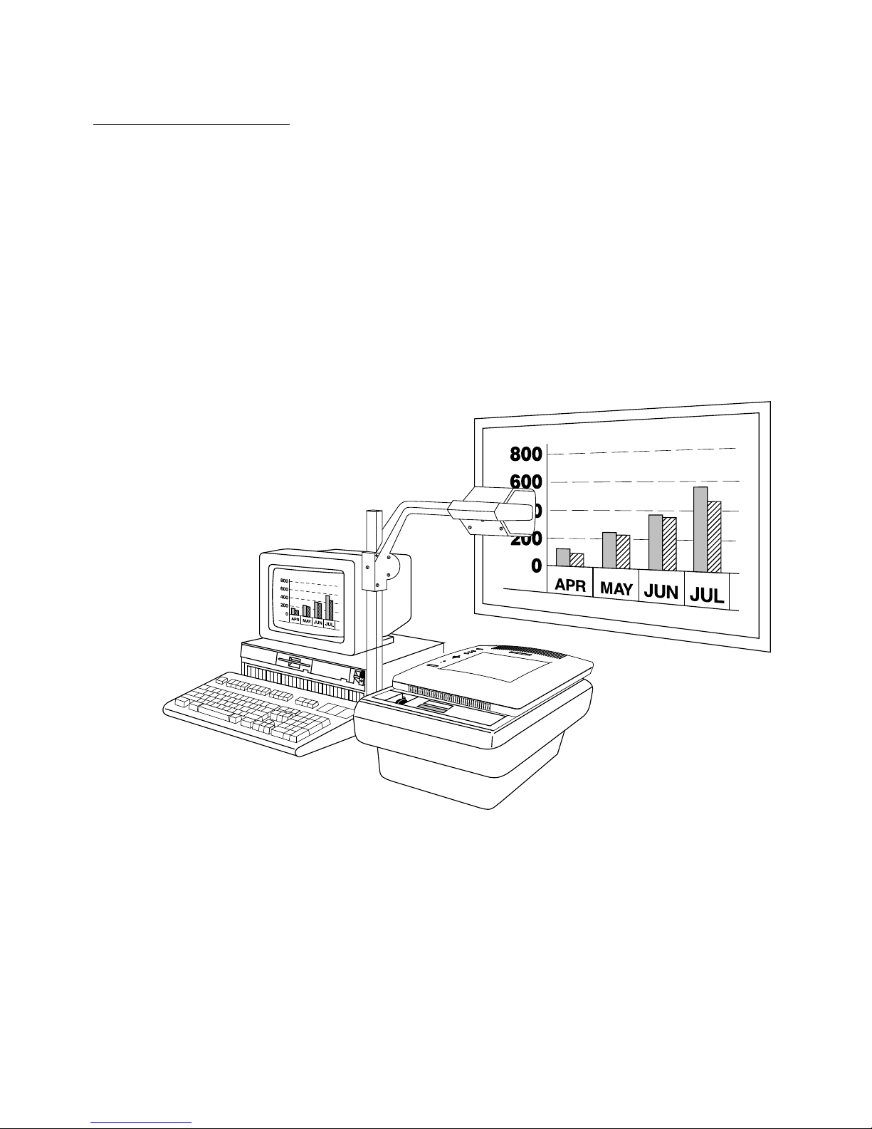
Congratulations on purchasing your new Ovation+ projection
panel - the most powerful projection panel available! This system
allows you to project the power of your computer in presentations
and workgroup meetings. The panel is designed to offer you
unsurpassed image quality, superior ease of use, and a wide variety
of features. And, the panel’s robust enclosure ensures that the
investment you have just made will continue to pay itself back
over many years of service.
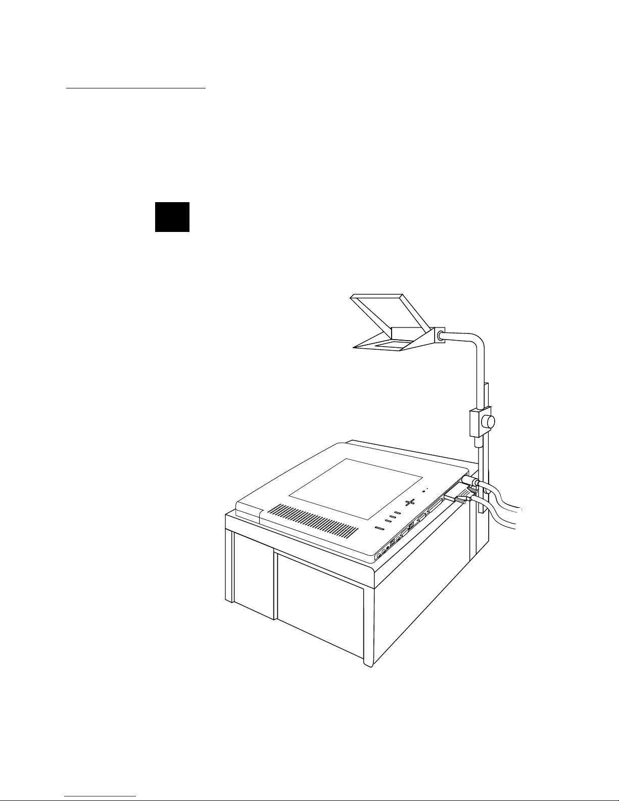
Figure 1
The Projection Panel
Among the many advanced features included in the projection
system are Proxima’s LightBoard
™
drawing tool, optional
integrated Cyclops
®
Interactive Pointer System capability, broad
cross-platform compatibility, serial mouse control, on-screen
graphical user interface, and user-customizable settings.
Page 4
1–2 • User’s Guide
Chapter 1 • The LCD Panel
The projection system consists of an active-matrix Liquid Crystal
Display (LCD) panel, a remote control, and appropriate cabling.
The active-matrix LCD provides superior image quality for both
still and full-motion video images.
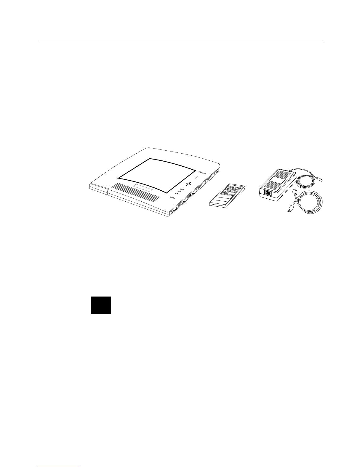
The packing box should contain the following items, along with
cables to connect the computer or video source to the projection
panel.
LCD Projection Panel
Remote Control
Transmitter
International AC
Power Supply
and Power Cord
AUDIO
Figure 2
The projection panel contents
International versions include additional power cords for
European, United Kingdom, and Italian electrical systems.
CAUTION! Treat the projection panel with care. Never lean it
against vertical surfaces or put it where it’s likely to fall.
☞
Page 5
User’s Guide • 1–3
Chapter 1 • The LCD Panel
Quick Start
This section lists quick setup directions for experienced users.
Control Panel
POWER
MENU
VIDEO
SYNC
- CONTRAST +
Figure 3
Control Panel
POWER Key Turn power on/off.
Arrow Keys Select menu items. Adjust image on screen.
MENU Key Enter and exit the menu system.
VIDEO Select a video source (on video-ready models
only).
SYNC Make minor adjustments in the timing of a
computer video image.
CONTRAST Increase or decrease the image contrast.
Page 6
1–4 • User’s Guide
Chapter 1 • The LCD Panel
Connector Panel
AUDIO IN
LEFT RIGHT
S-VHSAUDIO
OUT
VIDEO IN SERIAL
CYCLOPS
TO MAC MONITOR TO VGA MONITOR FROM COMPUTER
POWER
Figure 4
Connector Panel
AUDIO IN LEFT
AUDIO IN RIGHT
Plug Left Channel Audio into the White RCA
Connector.
Plug Right Channel Audio into the Red RCA
Connector.
AUDIO OUT Stereo audio output.
S-VHS Plug an S-VHS or S-Video source into this
connector.
VIDEO IN This yellow RCA connector is for video input.
SERIAL PORT Connect a Microsoft-compatible mouse to
this port to navigate menus or draw over the
projected image in "Local Mode", or to control
the computer's mouse functions in "Host
Mode".
CYCLOPS Connects the projection panel to the
computer in order to use the optional Cyclops
interactive pointer system, Presentation
Control Software, or a Microsoft-compatible
mouse.
TO MAC
MONITOR
Plug a Macintosh monitor cable into this
connector.
TO VGA
MONITOR
Plug a VGA monitor cable into this connector.
FROM
COMPUTER
Connect the computer to this DB25
connector.
POWER Plug the power cable from the power supply
into this connector. Then, connect the
appropriate IEC power cord to the universal
power supply.
Page 7

User’s Guide • 1–5
Chapter 1 • The LCD Panel
Connecting the Projection Panel
1. Turn off all power to the computer, monitor, and projection
panel.
2. Connect the power supply to the POWER connector on the
projection panel and plug the power cord into the wall outlet
(see Power Connection on page 2-3).
3. Connect a video cable between the computer’s Video Out
connector and the projection panel’s FROM COMPUTER
connector (see Computer Video Connection on page 2-3).
Note: Use of the projection panel with some laptops requires
pressing a combination of keys on the laptop to establish the
panel as an external monitor. Refer to the laptop manual for
information.
3. Connect a monitor (if desired) to the appropriate connector on
the projection panel (see Monitor Connection on page 2-7).
4. Refer to the Connector Panel table on page 1-4 or see
Chapter 2: Setting Up the Projection Panel to connect any
additional input devices.
5. Power up the projection panel, then the computer system.
Note: If the projection panel is on top of a lighted projector, a
sensor turns on the fan as a precaution to prevent overheating,
even if the power is off.
6. Calibrate Cyclops if there is a Cyclops interactive pointer
system installed. Refer to your Cyclops User’s Guide.
✍
✍
Page 8

1–6 • User’s Guide
Chapter 1 • The LCD Panel
Software
The projection panel does not require a separate device driver or
any other modification to the computer’s operating system. The
panel is fully compatible with all major software programs.
When using the optional Cyclops interactive pointer system or
Presentation Control Software, install the software drivers
provided with these products.
Several optional accessories and interface kits are available for the
projection panel. Refer to Appendix B: Accessories and Parts.
Accessories
Page 9
User’s Guide • 2–1
Chapter 2 • Setting Up the Projection Panel
Chapter 2
Setting Up
the Projection
Panel
This chapter describes the connections needed to set up the
projection panel.
CAUTION! Treat the projection panel with care. Never lean
it against vertical surfaces or put it where it’s likely to fall.
First, set up the computer, overhead projector, and viewing
screen. Set the projection panel on top of the overhead projector.
Figure 5
Projection panel on transmissive overhead projector
☞
Page 10
2–2 • User’s Guide
Chapter 2 • Setting Up the Projection Panel
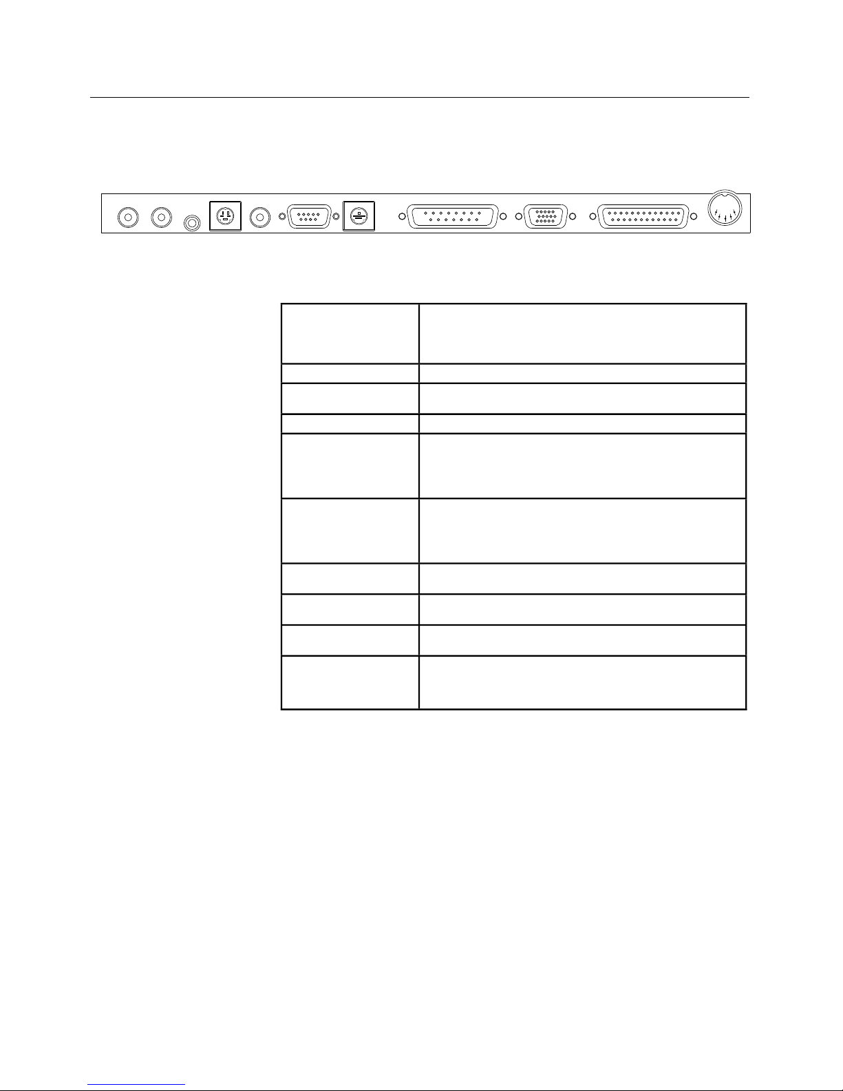
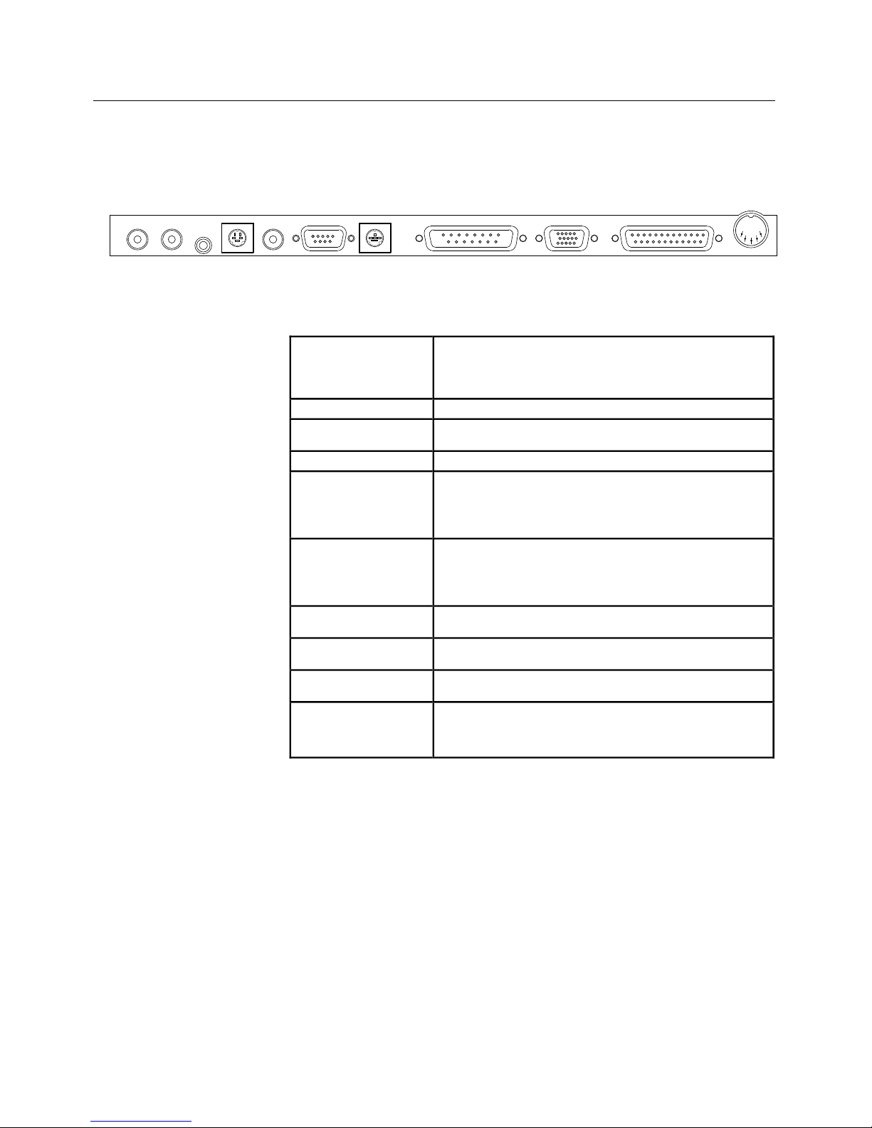
All connections between the projection panel and computer or
video source are made on the side connector panel.
Connector
Panel
Figure 6
Connector Panel
AUDIO IN LEFT
AUDIO IN RIGHT
Plug Left Channel Audio into the White RCA
Connector.
Plug Right Channel Audio into the Red RCA
Connector.
AUDIO OUT Stereo audio output.
S-VHS Plug an S-VHS or S-Video source into this
connector.
VIDEO IN This yellow RCA connector is for video input.
SERIAL PORT Connect a Microsoft-compatible mouse to
this port to navigate menus or draw over the
projected image in "Local Mode", or to control
the computer's mouse functions in "Host
Mode".
CYCLOPS Connects the projection panel to the
computer in order to use the optional Cyclops
interactive pointer system, Presentation
Control Software, or a Microsoft-compatible
mouse.
TO MAC
MONITOR
Plug a Macintosh monitor cable into this
connector.
TO VGA
MONITOR
Plug a VGA monitor cable into this connector.
FROM
COMPUTER
Connect the computer to this DB25
connector.
POWER Plug the power cable from the power supply
into this connector. Then, connect the
appropriate IEC power cord to the universal
power supply.
AUDIO IN
LEFT RIGHT
S-VHSAUDIO
OUT
VIDEO IN SERIAL
CYCLOPS
TO MAC MONITOR TO VGA MONITOR FROM COMPUTER
POWER
Page 11
User’s Guide • 2–3
Chapter 2 • Setting Up the Projection Panel
Power
Connection
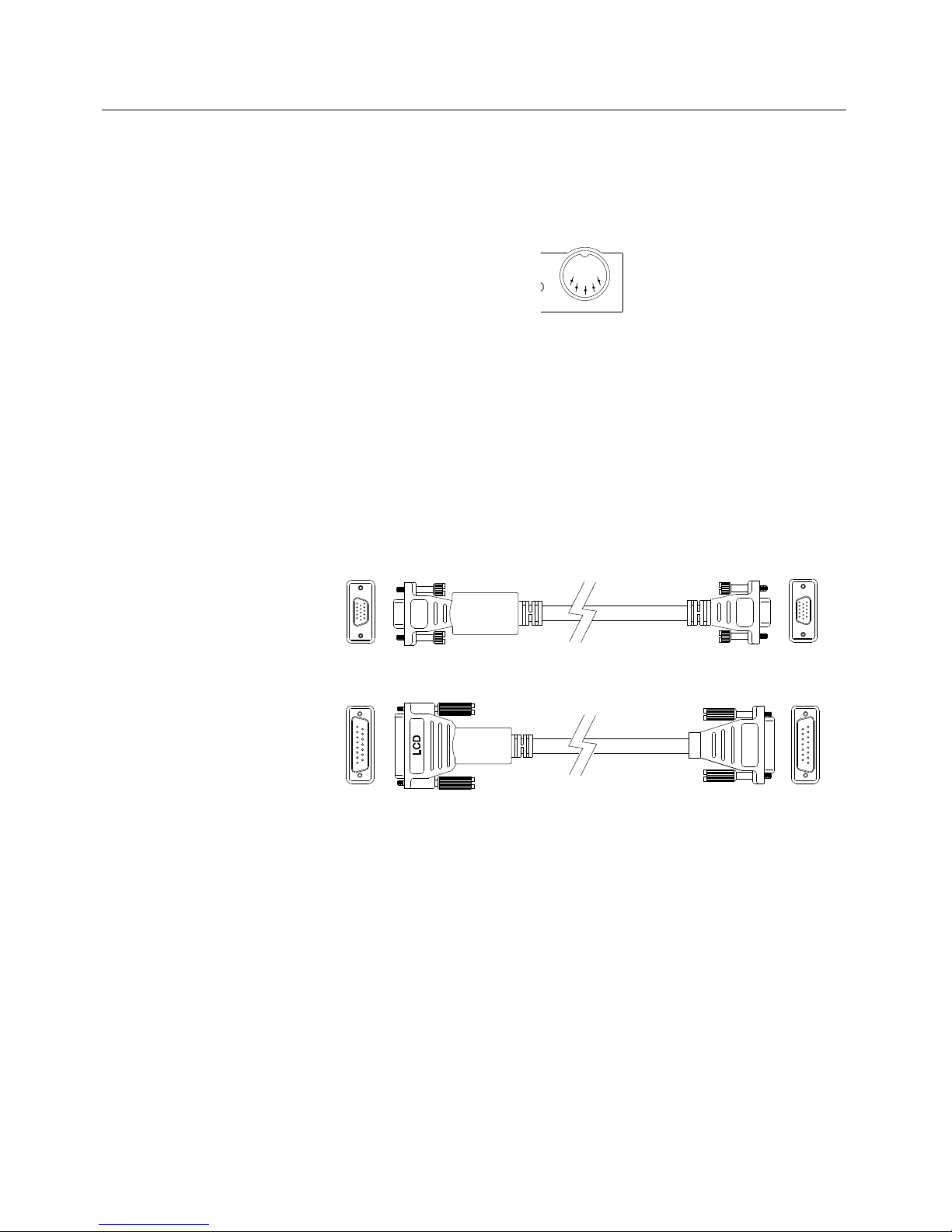
The power supply has a fixed cord ending in a circular plug with
five pins. Carefully insert this plug into the power port of the
projection panel.
POWER
Figure 7
The projection panel’s POWER port
Find the correct IEC power cord for the location. Plug the female
end into the power supply, and the male end into the wall outlet.
The cables shown below allow connection of IBM-compatible
(VGA) and Macintosh computers.
VGA Connector Cable
Macintosh Connector Cable
MAC
VGA
VGA
Figure 8
Computer connector cables
Computer
Video
Connection
Page 12

2–4 • User’s Guide
Chapter 2 • Setting Up the Projection Panel
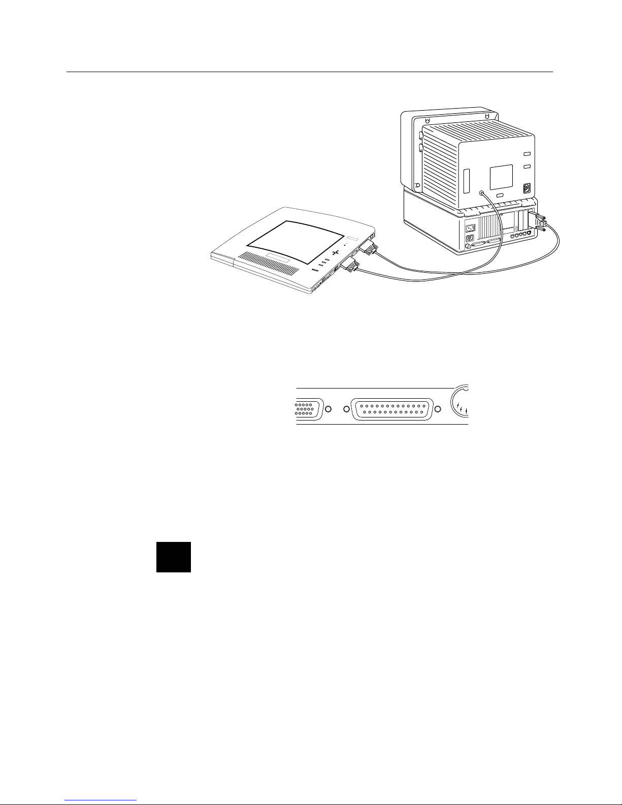
Desktop Computers
Use the appropriate cable to connect your desktop computer to
the projection panel.
1. Turn off power to the computer and projection panel.
2. Unplug the monitor cable from the computer’s Video Out
connector.
3. Connect the smaller end of the appropriate video cable to the
computer’s Video Out connector.
MONITOR
COMPUTER
PANEL
AUDIO
Figure 9
VGA Connections
Page 13
User’s Guide • 2–5
Chapter 2 • Setting Up the Projection Panel
MONITOR
MAC II/CPU
PANEL
AUDIO
Figure 10
Macintosh Connections
4. Connect the larger end of the cable to the projection panel’s
FROM COMPUTER connector.
A MONITOR FROM COMPUTER
POW
E
Figure 11
The projection panel’s FROM COMPUTER connector
5. If desired, connect an external monitor (see page 2-7) or power
up the hardware (projection panel first) to begin using the
system.
Note: An external monitor is not required to use the projection
panel.
✍
Page 14
2–6 • User’s Guide
Chapter 2 • Setting Up the Projection Panel
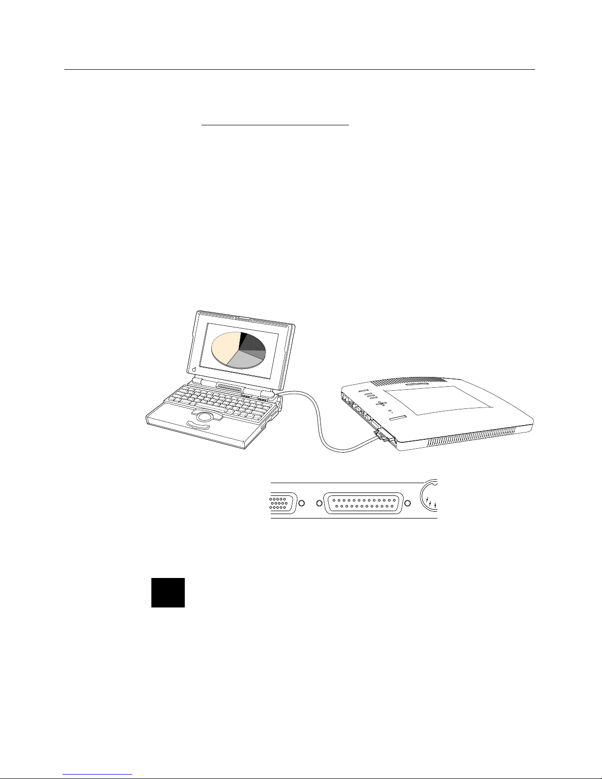
Laptop Computers
Use the appropriate cable to connect your laptop to the projection
panel.
1. Turn off power to the laptop and projection panel.
2. Connect the smaller end of the appropriate video cable to the
external Monitor connector.
3. Connect the larger end of the cable to the projection panel’s
FROM COMPUTER connector.
Figure 12
Laptop connections
Note: Use of the projection panel with some laptops requires
pressing a combination of keys on the laptop to establish the panel
as an external monitor. Refer to the laptop manual for
information.
✍
A MONITOR FROM COMPUTER
POW
E
Page 15
User’s Guide • 2–7
Chapter 2 • Setting Up the Projection Panel
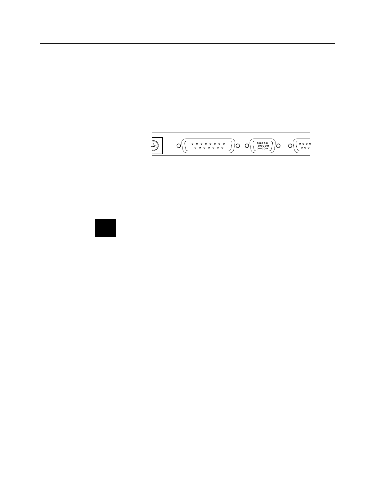
Monitor
Connection
Data can be viewed on a separate monitor in addition to the
projection panel. This connection can be made with the
projection panel and computer power on.
1. Connect the monitor’s video cable to the projection panel’s
TO MAC MONITOR or TO VGA MONITOR connector.
LOPS
TO MAC MONITOR TO VGA MONITOR FR
O
Figure 13
The projection panel’s TO MAC MONITOR and TO VGA
MONITOR connectors
2. Turn the monitor power on.
Note: Never connect monitors to the TO MAC MONITOR
and TO VGA MONITOR ports at the same time.
✍
Page 16

2–8 • User’s Guide
Chapter 2 • Setting Up the Projection Panel
CYCLOPS
Connection
Use the CYCLOPS connector to connect the projection panel to
the computer to use the optional Cyclops interactive pointer
system, the Presentation Control Software, or a Microsoftcompatible mouse (see page 3-5).
SERIAL
CYCLOPS
Figure 14
The projection panel’s CYCLOPS connector
The optional Cyclops or Presentation Control Software are
shipped with their own Installation and User’s Guides, and
additional cables (if needed) to connect the projection panel to
the computer.
1. Connect one end of the appropriate cable to the projection
panel’s CYCLOPS connector.
2. Connect the other end of the cable to the computer.
• On an IBM-compatible PC, connect the computer end to
a Serial port.
• On a Macintosh, connect the computer end to an ADB
connector.
Page 17
User’s Guide • 2–9
Chapter 2 • Setting Up the Projection Panel
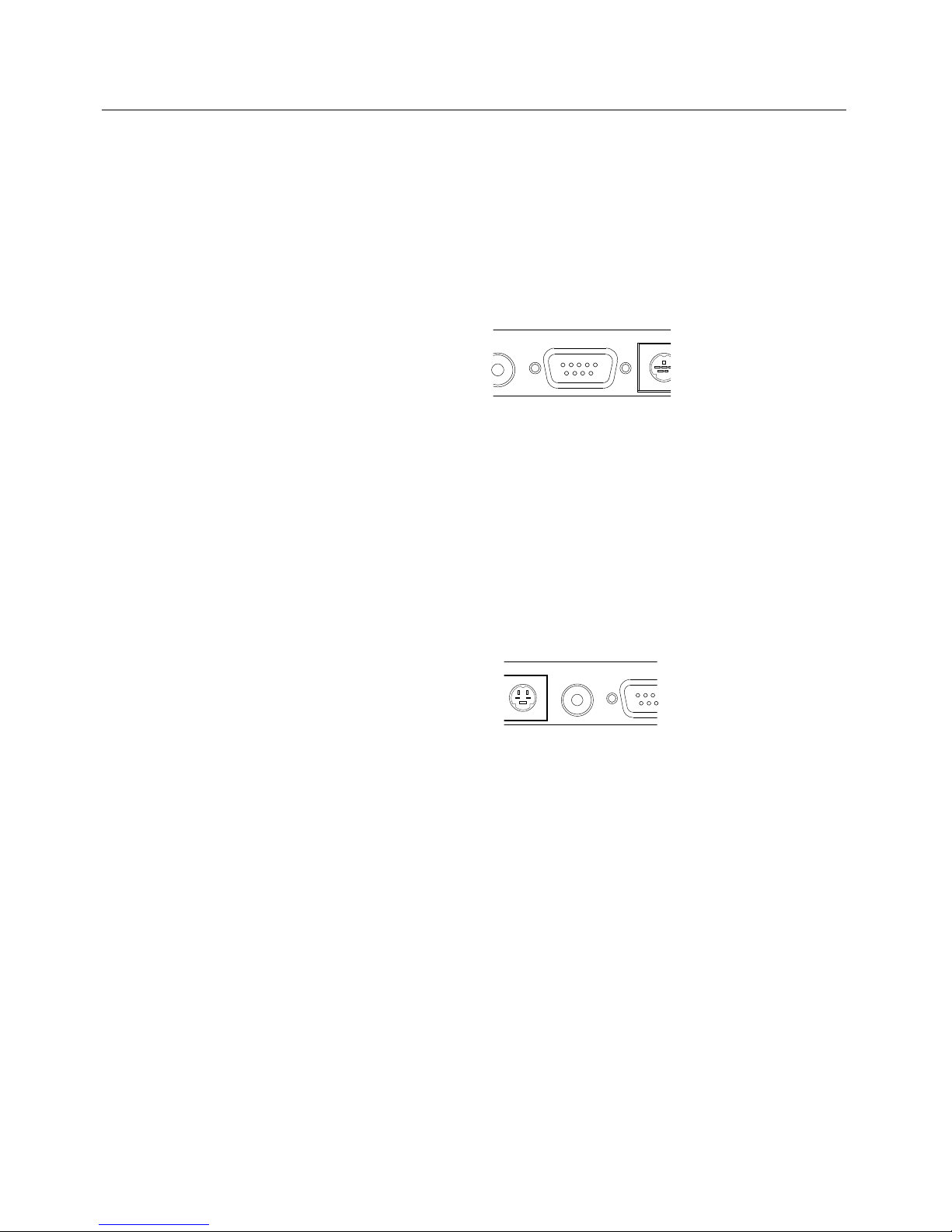
Serial Port
Connection
(To Panel)
A separate Microsoft-compatible mouse can be connected to the
SERIAL port connector on the projection panel to control the
panel’s built-in LightBoard drawing capability. This mouse can
also be used to navigate the panel’s menus in Local Mode (see
page 3-6) or function as the computer system’s mouse in Host
Mode.
EO IN SERIAL
CYCL
O
Figure 15
The projection panel’s SERIAL port connector
TV video (NTSC, PAL or SECAM) may be displayed on
video-ready projection panels. Find the circular connector on the
camcorder, laserdisc player, VCR, or other video source marked
Video Out or something similar. This connector accommodates
the RCA cable supplied with video-ready panel models. On most
video equipment, this connector will be yellow.
S-VHS
VIDEO IN SERI
A
Figure 16
The projection panel’s VIDEO IN connector for
NTSC/PAL/SECAM
The projection panel comes with an audio-visual cable with three
RCA connectors on each end.
1. Insert one of the cable’s yellow connectors into the VIDEO
OUT jack of the video source device.
2. Insert the other yellow connector into the projection panel’s
yellow VIDEO IN connector.
The audio-visual cable’s remaining connectors (red and white) can
be used to attach audio (see Audio Connections, page 2-11).
Video
Connections
Page 18

2–10 • User’s Guide
Chapter 2 • Setting Up the Projection Panel
S-VHS Video Connection
For an S-VHS (or S-Video) source, use an S-VHS cable instead of
the RCA cable connection described above. The S-VHS cable has
identical round, 4-pin DIN connectors on both ends.
S-VHS
UDIO
OUT
VIDEO
Figure 17
The projection panel’s S-VHS connector
1. Insert one end of the S-VHS cable into the VIDEO OUT jack
of the video source device.
2. Insert the other end of the S-VHS cable into the projection
panel’s S-VHS connector.
Page 19

User’s Guide • 2–11
Chapter 2 • Setting Up the Projection Panel
Video-ready projection panel models have three audio ports
labeled AUDIO IN LEFT (White), AUDIO IN RIGHT (Red)
and AUDIO OUT.
Stereo AUDIO IN
For true stereo audio when using a VCR or laser-disc, use the
supplied audio-visual cables to connect the audio source to the
projection panel.
1. Insert the white and/or red ends into the source’s AUDIO
OUT port(s).
2. Connect the other end(s) to the projection panel’s AUDIO IN
port(s). Be sure to connect Left to Left (White to White) and
Right to Right (Red to Red).
AUDIO IN
LEFT RIGHT
AU
D
O
U
Figure 18
The projection panel’s AUDIO IN connector
3. Make the required adjustments in the Audio menu
(see page 3-19).
For true stereo audio when using a computer, use the cable
supplied with your sound card to connect the audio source to the
projection panel.
1. Insert the cable’s mini-jack into your computer’s AUDIO
OUT port.
2. Connect the plugs on the other end to the panel’s AUDIO IN
ports.
3. Make the required adjustments in the Audio menu
(see page 3-19).
Audio
Connections
Page 20

2–12 • User’s Guide
Chapter 2 • Setting Up the Projection Panel
Mono AUDIO IN
Even if your audio source only outputs monaural audio, your
panel can output simulated stereo.
1. Choose the appropriate cable, and insert the appropriate
connector in your source’s AUDIO OUT port.
2. Connect the other end to the projection panel’s left or right
AUDIO IN port.
3. Make the required adjustments in the Audio menu
(see page 3-19).
Audio Follow
Your projection panel features Audio Follow capability. This
feature allows you to attach two video sources and the
accompanying audio to the projection system at the same time.
1. Connect monaural audio from your computer to the
projection system’s left AUDIO IN port.
2. Connect monaural audio from your VCR or laser-disc to the
projection system’s right AUDIO IN port.
3. Make the required adjustments in the AUDIO menu
(see page 3-19).
As you toggle between your sources, the audio follows the
associated video. You always get simulated stereo output.
Page 21

User’s Guide • 2–13
Chapter 2 • Setting Up the Projection Panel
AUDIO OUT
Use a stereo mini-jack cable to connect the projection panel’s
AUDIO OUT port to a separate amplifier or amplified speakers.
For more information, refer to the amplifier system manual.
IGHT
S-V
H
AUDIO
OUT
Figure 19
The projection panel’s AUDIO OUT connector
Page 22

User’s Guide • 3–1
Chapter 3 • Using the Projection Panel
Chapter 3
Using the
Projection
Panel
The monitor and projection panel should be powered-up before
the computer, so that the computer senses the display(s) during its
boot-up sequence. When POWER is pressed to turn the panel on,
the POWER light illuminates. If the key is pressed again, the light
goes out and power is off.
Note: If the projection panel is on top of a lighted projector, a
sensor turns on the fan as a precaution to prevent overheating,
even if the panel’s power is Off.
CAUTION! Never operate the projection panel if the cooling
slots are clogged or obstructed, or if the electric fan inside the unit
has failed. Never unplug the power cord while it is still on top of a
lighted projector.
AUDIO
Figure 20
Allow for proper air flow
Note: Liquid crystals freeze at low temperatures. There is no
harm in this. If the projection panel is ever exposed to extremely
cold temperatures, allow it to warm to room temperature before
use.
Powering Up
☞
✍
✍
Page 23

3–2 • User’s Guide
Chapter 3 • Using the Projection Panel
Control Panel
The projection panel’s Control Panel keys are used to adjust the
projected image and to display or hide the menu.
POWER
MENU
VIDEO
SYNC
- CONTRAST +
Figure 21
Control Panel
Key Function
POWER Turns projection panel power on and off.
Arrow Keys 1. Press Left/Right to select a menu function.
Press Up/Down to change the selected
value.
2. Use the Arrow keys to adjust the position
of a full-screen image on the screen.
3. The Arrow keys are also used to pan to
parts of the image that are not shown in
the current view (PAL, SECAM only).
MENU Press the MENU key to display the Menu
Window in the upper portion of the projected
image. The Menu remains on-screen until the
MENU key is pressed again. Menu settings are
automatically stored when the menus are exited
or the projection panel is turned off.
VIDEO Press the VIDEO key to cycle between
computer video, composite video, or S-VHS
input.
SYNC Use this key if text or graphic images "shimmer".
Press SYNC repeatedly to fine tune the video
signal.
CONTRAST Use this key (- and +) to adjust the amount of
contrast in the projected image.
Note: The VIDEO key does not function on the non-video
model of the projection panel.
✍
Page 24

User’s Guide • 3–3
Chapter 3 • Using the Projection Panel
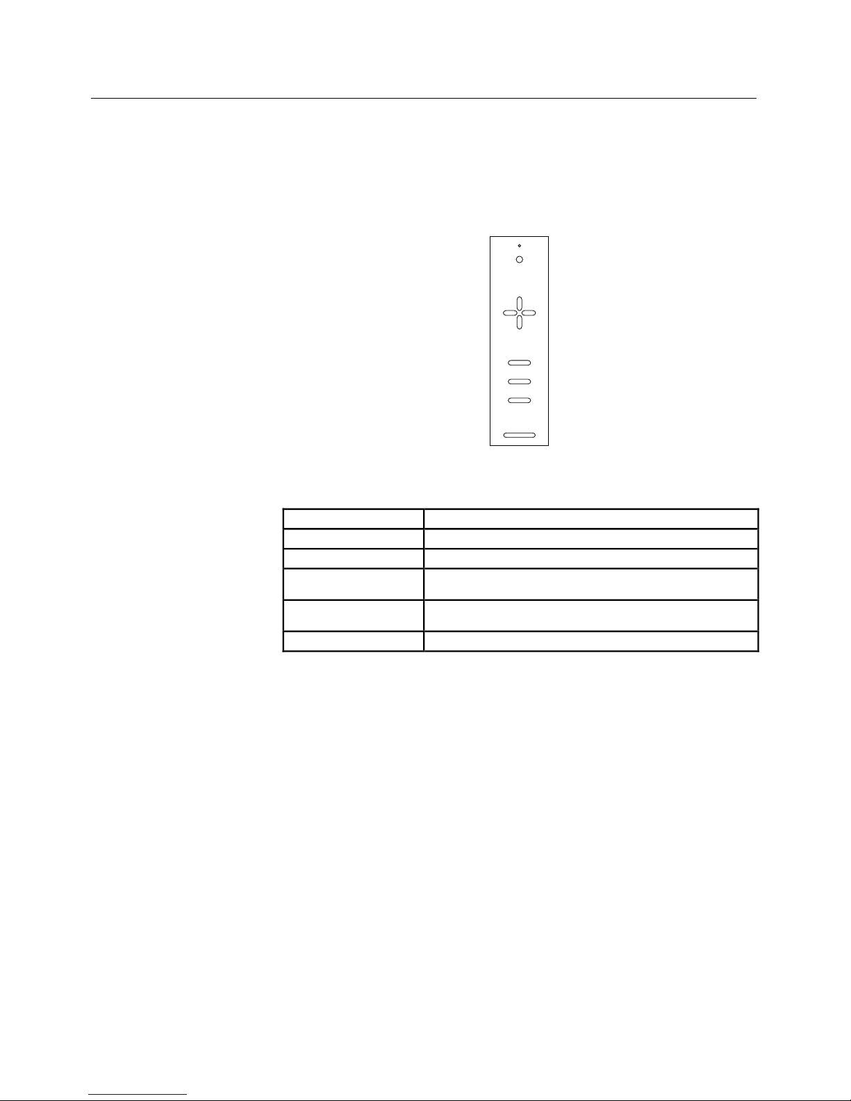
The Remote
Control
The Remote Control allows you to control the projection panel
from a distance by aiming it at the front of the panel or the
projection screen. The panel sees the reflected beam and responds
to it.
ZOOM - VOLUME +
MUTE
TEXT
FREEZE SYNC
VIDEO
MENU
- CONTRAST +
PROG
Figure 22
The Remote Control Unit
Page 25

3–4 • User’s Guide
Chapter 3 • Using the Projection Panel
The Remote Control has the following keys:
Key Function
Arrow Keys 1. Press Left/Right to select a menu function. Press
Up/Down to change the selected value.
2. Use the Arrow keys to adjust the position of a full screen image on the screen.
3. The Arrow keys are also used to pan to parts of the
image that are not shown in the current view (PAL,
SECAM only).
MENU Press the MENU key to display the Menu Window in the
upper portion of the projected image. The Menu remains
on-screen until the MENU key is pressed again. Menu
settings are automatically stored when the menus are
exited or the projection panel is turned off.
VIDEO Press the VIDEO key to cycle between computer video,
composite video, or S-VHS input (on video-ready models
only).
MUTE Press MUTE once to mute the volume. Press it a
second time to return the volume to its previous level.
ZOOM Use this key to scale a PAL or SECAM image to fit the
full viewing area.
TEXT Press TEXT to toggle VGA text modes from 640x400
to 720x400.
VOLUME -/+ Press – to decrease, + to increase volume.
FREEZE Press this key to freeze a video source image. Press
again to return to full motion.
SYNC Use this key if text or graphic images "shimmer". Press
SYNC repeatedly to fine tune the computer video signal.
CONTRAST -/+ Use this key (- and +) to adjust the amount of contrast in
the projected image.
PROG Assign a specific projection panel function to this user -
programmable key (see Preferences Menu, page 3-23).
Presentation
Control
Software Keys
The Remote Control can also be used to move forward
and backward in computer slide shows when using the
Presentation Control Software. The computer and
projection panel must be connected through the serial
port in order for this software to work. For more
information, please refer to page 2-9.
Program this key through the Presentation Control
Software. This key is typically used to move the
presentation back one frame.
Program this key through the Presentation Control
Software. This key is typically used to pause the
presentation.
Program this key through the Presentation Control
Software. This key is typically used to move the
presentation forward one frame.
Page 26

User’s Guide • 3–5
Chapter 3 • Using the Projection Panel
The projection panel is simple to operate and can be controlled
several different ways. The projection panel’s menus can be
accessed and controlled via the Control Panel, the Remote
Control, a Microsoft-compatible mouse or the optional Cyclops.
The panel’s LightBoard function can be controlled with the
optional Cyclops or a Microsoft-compatible mouse. The
Presentation Control Software can be controlled using the
Remote Control.
The Control Panel and Remote Control
The Control Panel and Remote Control provide access to all of
the projection panel’s functions and modes. Simply press a key to
select a function or to move through the menus.
Using a Microsoft-Compatible Mouse
A Microsoft-compatible mouse can be used to control the menu
and the LightBoard tool in Local Mode and as a system mouse in
Host Mode (see page 3-7). The mouse must be connected to the
serial port on the projection panel before powering up the panel.
Note: A Microsoft mouse driver must be loaded and running
on the computer system for Host Mode functions. In addition, in
order to control the host computer with Cyclops or with a mouse
attached to the panel, an optional data cable must be attached
between the panel and the computer. Contact your dealer to
purchase the appropriate data cable.
Operating the
Projection
Panel
✍
Page 27

3–6 • User’s Guide
Chapter 3 • Using the Projection Panel
Operating Modes
The panel and its control devices can operate in two modes: Local
Mode and Host Mode.
Local Mode
Anytime the panel’s menus or LightBoard are activated, the panel
is in Local Mode.
In Local Mode, the projection panel mouse or the optional
Cyclops is used for projection panel menu and LightBoard
functions only; it does not communicate with the computer.
In Local Mode, the projection panel mouse or Cyclops can be
used to:
• Move through an open projection panel menu.
• Select items in an open projection panel menu.
• Control the LightBoard cursor.
Page 28

User’s Guide • 3–7
Chapter 3 • Using the Projection Panel
Host Mode
If a mouse or Cyclops and a data cable are connected to the panel,
it can also operate in the Host Mode. Host Mode can only be
used when the panel’s menu and LightBoard are not active. This
means that the panel and its control devices are communicating
directly with the host computer.
In Host Mode, the projection panel mouse functions as the
system mouse. It communicates with the computer and controls
the screen cursor for all computer functions.
• If the projection panel’s I/O port is sensed first during the
computer’s start-up, the projection panel mouse becomes the
system mouse and the computer mouse is not seen.
• If the computer mouse is seen first and the user wants the
panel mouse to be the system mouse, the user must switch the
mouse and projection panel ports and restart the computer.
• If you are in Host Mode and the panel menus or LightBoard
are selected, the projection panel mouse is forced to Local
mode operation until those functions are turned off.
Please refer to the Cyclops 2050 User Guide for projection panel
Host Mode mouse operation with a Cyclops module installed.
Page 29

3–8 • User’s Guide
Chapter 3 • Using the Projection Panel
The Graphical
User Interface
Your projection system features a graphical user interface that
allows easy control of menus and your panel’s many functions.
You will find that each interface method discussed below provides
you with increasing power over your presentation system.
Control Panel and Remote Control
Menu selections can be easily made with the Control Panel or the
Remote Control.
1. Press the MENU key to display the on-screen menus.
2. Press the Up and Down arrow keys to select the desired menu.
When a menu is selected, the currently active settings are
highlighted.
3. Use the Left and Right arrow keys to move across the menus to
the setting to be changed.
4. Use the Up and Down arrow keys to change the selected value.
5. Press the MENU key again to close the menus. Settings are
automatically saved when the menus are exited or the
projection panel is turned off.
Controlling Menus with a Mouse
If a Microsoft-compatible mouse is connected to the projection
panel’s SERIAL port, menu selections are even easier. When the
menus are open, simply point at a desired selection and click to
select or change it.
Page 30

User’s Guide • 3–9
Chapter 3 • Using the Projection Panel
Cyclops Interactive Pointer System
For the ultimate in functionality, you can use the optional
Cyclops Interactive Pointer System to control the menus and
LightBoard draw program (see page 3-11) in Local Mode, and the
attached computer in Host Mode (see page 3-6).
To open or close the menus, simply point the Cyclops wand or
laser pointer to the left or right of the projected image, and hold
the button down until the menus appear or disappear. As with
the Microsoft-compatible mouse, menus can be controlled with a
point and click.
To open or close the LightBoard draw program, simply point the
Cyclops wand or laser pointer above the projected image, and
hold the button down until the LightBoard tool bar appears or
disappears.
Click here with Cyclops for LightBoard
Click on either side of display
for menus to be displayed
Figure 23
Cyclops activation of menus and LightBoard
Page 31

3–10 • User’s Guide
Chapter 3 • Using the Projection Panel
Using
the Menus
When the MENU key is pressed or when Cyclops is used to open
the menus (see page 3-9), a menu bar appears at the top of the
screen.
Input Source
Image
Audio
Preferences
Advanced
MENUS
Cyclops
Calibrate
Calibrate
No Calibrate
Right
Center
None
Button
Left
LightBoard
Figure 24
Main Menu
Note: The menu displays only those items that are relevant to
the selected input source (computer, video, and S-VHS). The
menus shown in the following illustrations are the full menus.
Menu Actions
LightBoard Highlight text or other objects on the screen using
this built-in draw tool with Cyclops or a mouse.
Functions include:
• Overlay: Allows the user to draw or annotate
over the displayed image.
• WhiteBoard: Clears the screen and provides
bright background for the Draw tool.
• BlackBoard: Clears screen and provides dark
background for Draw tool.
Cyclops Set up and calibrate the Cyclops Interactive Pointer
System.
Input Source Select a video source.
Image Adjust the settings of an incoming video signal.
Audio Control the audio volume and balance.
Preferences Program a custom key on the Remote Control,
select the option for rear projection, or change the
language of the menu displays.
Advanced Set up separate custom settings for 2 users for
each video mode.
Press the MENU key again or use Cyclops (see page 3-9) to turn
the Menu off.
✍
Page 32

User’s Guide • 3–11
Chapter 3 • Using the Projection Panel
LightBoard Menu
This menu sets up and activates the projection panel’s built-in
LightBoard draw program. LightBoard allows highlighting of text
or other objects on the screen and drawing on a whiteboard or
blackboard with Cyclops or a mouse.
Overlay
WhiteBoard
BlackBoard
Cyclops
Input Source
Image
Audio
Preferences
Advanced
MENUS
LightBoard Mode
Off
On
LightBoard
LightBoard
Figure 25
LightBoard Menu
LightBoard functions include:
• Overlay: Allows use of the Draw tool to highlight or annotate
the displayed image.
• WhiteBoard: Clears the screen and provides a bright
background for the Draw tool.
• BlackBoard: Clears the screen and provides a dark background
for the Draw tool.
These functions can also be accessed with the PROG key settings
via the Remote Control (see page 3-23).
Page 33

3–12 • User’s Guide
Chapter 3 • Using the Projection Panel
To use the LightBoard:
1. Access the LightBoard menu and choose On. The Draw tool
bar appears in the upper left of the display.
2. The currently selected tool (Draw or Erase) is highlighted and
a cursor appears. Use the Cyclops wand, laser pointer or a
Microsoft-compatible mouse attached to the SERIAL port to
draw on the screen.
The Draw tool bar has four options:
Click this button to select the Drawing tool.
Click this button to select the Eraser. You can
erase portions of your highlights.
Click the Clear All button to erase all previous
highlighting.
Click this button to select a new color. This button
shows the currently selected color.
To open the color pallette:
1. Click the Color box or the icon in the upper right corner of
the Draw tool bar. Eight color selection boxes appear.
Page 34

User’s Guide • 3–13
Chapter 3 • Using the Projection Panel
2. Click on the color you want to use. The Color box takes on
the selected color, and the color pallette remains available.
Figure 26
Color selection boxes
3. Click the Color box or the icon in the upper right corner again
to turn the color selection boxes off.
4. To draw, click and hold down the Cyclops or mouse button at
the desired starting point. Draw with the cursor and release the
mouse or wand button to end a draw motion.
5. The Draw tool bar can be moved to another location on the
screen. With the mouse or Cyclops wand, click and hold on
the top of the tool bar. Drag the bar to the new location and
release the mouse or wand button.
6. To exit the Draw function, click the small box in the upper left
corner of the Draw tool bar.
Page 35

3–14 • User’s Guide
Chapter 3 • Using the Projection Panel
Cyclops Menu
This menu allows you to adjust the optional Cyclops interactive
pointer system settings.
Input Source
Image
Audio
Preferences
Advanced
MENUS
Cyclops
Calibrate
Calibrate
No Calibrate
Right
Center
None
Button
Left
LightBoard
Figure 27
Cyclops Menu
Menu Item Settings
Calibrate Select Calibrate to calibrate the Cyclops system for
image size and ambient lighting conditions. Point and
click the wand or laser pointer at the point of each
of the four screen arrows displayed on the image.
Button Use this menu to choose which mouse button
action to send to the computer when the Cyclops
spot is detected.
Note: For more information about setting up and using
Cyclops, refer to the Cyclops User’s Guide.
✍
Page 36

User’s Guide • 3–15
Chapter 3 • Using the Projection Panel
Input Source Menu
This menu provides a two-step method of selecting the video
source. When a video input is connected, the Source Mode box
indicates which video source has been detected by the projection
panel.
Input Source
Image
Audio
Preferences
Advanced
MENUS
LightBoard
Cyclops
Video
S-VHS
Source Select
Computer
Current Mode:
VESA 480/72
640 x 480 72Hz
Source Mode
VESA
640 x 480 72Hz
Figure 28
Input Source Menu
1. To change the Source Mode setting, move to the Source Select
box and use the Up and Down arrow keys, mouse, or Cyclops
to select Computer, Video or S-VHS in the Source Select box.
2. The Source Mode box lists all of the input sources recognized
by the projection panel that match or are close to the current
source. Move to the Source Mode box and use the Up and
Down keys to highlight a different input source.
Input Source
Image
Audio
Preferences
Advanced
MENUS
LightBoard
Cyclops
Video
S-VHS
Source Select
Computer
VGAText
VGA Text
Current Mode:
Source Mode
VGA400
VGA 400 Lines
VGAText
VGA Text
Think/VGA Text
ThinkPad Text
Cancel Select
Figure 29
Computer Input Source Menu
Page 37

3–16 • User’s Guide
Chapter 3 • Using the Projection Panel
If Video is selected, the Source Mode box allows the selection
of NTSC, PAL, or SECAM video. The projection panel
automatically detects the format of a connected video source
(either NTSC or PAL/SECAM). When it detects a signal that
may be either PAL or SECAM, the panel initially defaults to
PAL.
Computer
Video
S-VHS
Source Select
Current Mode:
NTSC 60Hz
PAL 50Hz
SECAM 50Hz
Cancel Select
NTSC 60Hz
Source Mode
Input Source
Image
Audio
Preferences
Advanced
MENUS
LightBoard
Cyclops
Figure 30
Video Input Source Menu
3. Use the Arrow keys to either Cancel (Left key) or Select
(Right key) the new source entry.
Page 38

User’s Guide • 3–17
Chapter 3 • Using the Projection Panel
Image Menu
Computer Video
When computer video is displayed, the Image Menu displays a
series of video adjustment windows. The horizontal bars move up
or down to indicate the current setting.
Contrast Sync Pixel Skip
Dot Clk
Colors
226000
16.7 million
Input Source
Image
Audio
Preferences
Advanced
MENUS
LightBoard
Cyclops
Figure 31
Computer video IMAGE Menu
Menu Item Settings
Contrast Use this setting (+ and -) to increase or decrease
the contrast level of the projection panel.
Sync Use the Sync setting to compensate for fine
variations in the video signal timing of a computer.
Adjust this setting if uneven horizontal features are
seen, such as lines of text, streaks or shimmering
in a graphics image.
Pixel Skip Use this setting to adjust the appearance of VGA
text on the screen (this menu item appears in VGA
text mode only).
Dot Clock Use the Up or Down arrow keys to adjust the Dot
Clock. This may be required if vertical black lines on
the screen are seen or when fine tuning your
image.
Colors Switch between 226,000 and 16.7 million colors.
The best number of colors is dependent on the
input source.
Note: Do not adjust the Dot Clock until you have tried to
fine tune the picture with the Sync setting.
✍
Page 39

3–18 • User’s Guide
Chapter 3 • Using the Projection Panel
NTSC/PAL/SECAM or S-Video
When the Image menu is selected for an NTSC/PAL/SECAM or
S-Video source, the following menu appears. Adjust the
individual settings to achieve the best picture.
Contrast Brightness Tint Saturation
Input Source
Image
Audio
Preferences
Advanced
MENUS
LightBoard
Cyclops
Normal View
Fit to View
Zoom
Figure 32
Image Menu for a video source
Menu Item Settings
Contrast Use this setting (+ and -) to increase or decrease
the contrast level of the projection panel.
Brightness Use the Up and Down arrow keys to make the
screen image brighter or darker.
Tint Use the Up and Down arrow keys to make the
screen image more red or green.
Saturation Use the Up and Down arrow keys to increase or
decrease the saturation of the screen colors.
Zoom In PAL or SECAM modes, choose Normal View to
view an unscaled image, or Fit to View to view the
image scaled to fit the display.
Page 40

User’s Guide • 3–19
Chapter 3 • Using the Projection Panel
Audio Menu
The Audio menu allows adjustment of the volume, balance and
tone of the projection panel’s audio output.
Volume Mute Balance Treble Bass
Normal
Mute
Source
Stereo
Left
Right
LightBoard
Cyclops
Input Source
Image
Audio
Preferences
Advanced
MENUS
Figure 33
Audio Menu
Menu Item Settings
Volume Adjusts the volume of an audio source connected to
the projection panel.
Mute Mutes the Audio output.
Balance Adjusts the balance between the left and right
speakers.
Treble Adjusts the treble tone.
Bass Adjusts the bass tone.
Source Controls which audio channel(s) are active.
1. Select Stereo when playing a stereo source from
both left and right inputs.
2. Computer audio can be assigned to the left
channel and video source audio to the right
channel. The audio signal follows the video when
you switch sources (see page 2-12).
The projection panel provides a left and right
signal through the AUDIO OUT connector,
allowing simulated stereo no matter which signal
is active (see page 2-13).
Page 41

3–20 • User’s Guide
Chapter 3 • Using the Projection Panel
As described in Audio Connections (see p. 2-11), you can
incorporate audio into your presentation in a variety of ways. In
order to configure your system, follow the instructions below.
Stereo Audio
If you wish to use a source with true stereo audio output,
complete the following steps:
1. Open the Input Source menu and access Source Select.
2. Choose the source (e.g. Video).
3. Open the Audio menu and access Source.
4. Choose Stereo.
The source you chose under the Input Source menu (in this case,
Video) will now accept and output stereo audio.
If you will be using another video source (e.g. Computer), but do
not want any audio associated with it, complete the following
additional steps:
5. Return to the Input Source menu and access Source Select.
6. Choose the source (e.g. Computer) you will be using without
any audio.
7. Open the Audio menu and access Mute.
8. Select Mute.
When you close the menus, the settings will be saved. In the
above example, the panel will activate stereo audio when you
select your Video source and will mute all audio when you select
your Computer source.
Page 42

User’s Guide • 3–21
Chapter 3 • Using the Projection Panel
Mono Audio
If you are using a monaural source but wish to simulate stereo
output, complete the following steps:
1. Open the Input Source menu and access Source Select.
2. Choose the source (e.g. Video).
3. Open the Audio menu and access Source.
4. If the monaural source is connected to the AUDIO IN Left
connector (see page 2-12), choose Left. If the monaural
source is connected to the AUDIO IN Right connector (as in
this example), choose Right.
The source you chose under the Input Source menu (in this case,
Video) will now accept monaural input and will output simulated
stereo audio.
If you will be using another video source (e.g. Computer), but do
not want any audio associated with it, complete the following
additional steps:
5. Return to the Input Source menu and access Source Select.
6. Choose the source (e.g. Computer) you will be using without
any audio.
7. Open the Audio menu and access Mute.
8. Select Mute.
When you close the menus, the settings will be saved. In the
above example, the panel will activate simulated stereo audio
when you select your Video source and will mute all audio when
you select your Computer source.
Page 43

3–22 • User’s Guide
Chapter 3 • Using the Projection Panel
Audio Follow
In order to take advantage of your projection system’s Audio
Follow feature (see page 2-12), complete the following steps:
1. Open the Input Source menu and access Source Select.
2. Choose Computer.
3. Open the Audio menu and access Source.
4. Choose Left.
5. Return to the Input Source menu and access Source Select.
6. Choose Video.
7. Open the Audio menu and access Source.
8. Choose Right.
When you close the menus, the settings will be saved. As you
toggle between your sources, the audio will follow the associated
video source. You will always get two channels out, providing
simulated stereo output.
Note: Audio Follow will not work with Video and S-VHS
simultaneously. Only one television video source (Video or SVHS) can have access to audio functionality at a time.
✍
Page 44

User’s Guide • 3–23
Chapter 3 • Using the Projection Panel
Preferences Menu
This menu is used to tailor the projection panel to a personal
presentation style.
Language
English
Deustch
Francais
Espanol
Italiano
Projection
Front
Rear
On-screen
Display
Hide
Prog. Key
LightBoard
Reverse
Clear
Colors
Audio Source
Left Button
Right Button
Center Button
LightBoard
Cyclops
Input Source
Image
Audio
Preferences
Advanced
MENUS
Figure 34
Preferences Menu
Menu Item Settings
Language Menus can be displayed in any of five languages.
Projection Select front or rear projection.
On-screen Display or hide the on-screen menu displays. When
Display is selected, slide bars appear on screen when
certain settings are adjusted with the Remote
Control or Control Panel.
Prog. Key Assign a specific projection panel function to the
PROG key on the Remote Control as a shortcut:
• LightBoard – Opens or closes the Draw tools.
• Reverse – Switches between Normal and Reverse
video.
• Clear – Blanks the screen so that you can show a
transparency on the overhead projector.
• Colors – Toggles between the two color settings.
• Audio Source – Switches between audio sources.
• Left Button – Toggles mouse button functions
between the default setting and the left button.
• Right Button – Toggles mouse button functions
between the default setting and the right button.
• Center Button - Toggles mouse button functions
between the default setting and the center button.
Page 45

3–24 • User’s Guide
Chapter 3 • Using the Projection Panel
Advanced Menu
This menu is used to adjust the image and to select a set of
customized values.
User
Default
User A
User B
Rev. Video
Normal
Reverse
Mode Reset
Off
Reset Mode
LightBoard
Cyclops
Input Source
Image
Audio
Preferences
Advanced
MENUS
Figure 35
Advanced Menu
Menu Item Settings
User Select one of the custom user sets of stored
defaults.
Rev. Video Select Rev. Video to apply a photographic negative
effect to the image. This is useful for viewing text based applications.
Mode
Reset
Select Reset Mode to return the Dot Clock and
customized settings for the current video source to
the factory defaults.
Custom Settings
Some settings may be adjusted to suit a particular presenter’s style
or taste. You may customize and save video mode adjustments
and image settings for two additional users by accessing the User
Menu in the Advanced Menu.
Page 46

User’s Guide • 3–25
Chapter 3 • Using the Projection Panel
A set of customized values for every video mode (VGA,
Macintosh II, NTSC/PAL/SECAM, etc.) can be stored for the
Default user, User A, or User B.
To save a custom setting:
1. Select Default, User A, or User B under the User Menu in the
Advanced Menu.
2. Make any projection panel adjustments desired (these changes
only affect the currently displayed mode).
When you change a setting, two small bars appear to indicate
the factory default values for that setting. These bars will
disappear when you use the Remote Control, Cyclops or
mouse to return to the setting’s default.
Contrast Brightness Tint Saturation
Input Source
Image
Audio
Preferences
Advanced
MENUS
LightBoard
Cyclops
Normal View
Fit to View
Zoom
Figure 36
Default and current settings
3. Close the menus to save changes.
The adjustments are recalled simply by selecting the correct User
(the Default user is the default upon power up; select User A or B
as required). The projection panel then recognizes the video input
and recalls the customized settings.
Page 47

User’s Guide • 4–1
Chapter 4 • Maintenance
Chapter 4
Maintenance
The projection system requires minimal maintenance.
Slide the battery compartment open to change batteries.
Figure 37
Installing batteries (Use 2 AAA size batteries)
To clean the top or bottom protective glass, put a small amount
of glass cleaner on a soft cloth or lens cleaning tissue. Gently wipe
the glass plate to remove any accumulated dust or grit.
Changing
Remote
Control
Batteries
Cleaning
the Glass
Page 48

User’s Guide • 5–1
Chapter 5 • Troubleshooting
Chapter 5
Troubleshooting
Please refer to this troubleshooting chart before calling a reseller for assistance.
Problem Likely Cause Possible Solution
No computer image
projected
1. Loose cable
2. No power to computer
3. Incompatible video
system
4. No power to projection
panel
5. External port not
activated
6. Overhead projector
lamp not turned on.
1. Check and secure cable
connections
2. Turn on computer
3. If possible, check computer
with another monitor
4. Power up panel; Plug in AC
cord (both ends); Make sure
outlet is on
5. Activate the external port on
your laptop
6. Turn the overhead projector
on
No image on computer
screen
Cable not connected Connect cable
Monochrome on color
monitor
Computer was turned on
before projection panel
Turn projection panel on, then
re-boot computer
Streaks on monitor Video cable plugged into
computer is upside-down
Check and re-set cable
connections
Faint screen Low contrast Adjust CONTRAST
Jittery, fuzzy letters Out of sync Adjust SYNC control
Image off-center Position controls (arrow
keys)
Adjust position controls; if image
will not center, check for
compatibility problems
Cannot get entire image
on screen; scrambled
image
Compatibility problem Make sure your system is
compatible with one of the
standards listed in Appendix A
One or more colors
“shimmer ” on-screen
SYNC or CONTRAST is
out of adjustment
Adjust SYNC or CONTRAST keys
No video image projected 1. Video Source(s)
improperly set-up
2. Loose/improper cabling
1. Check video source(s)
(composite or S-VHS) for
power on and proper
operations
2. Check and secure cabling
between video source(s) and
projection panel
Colors weak in video
(NTSC/PAL/SECAM) mode
1. Weak video signal
2. CONTRAST setting
may be too low
1. Check for faulty video
source, bad connection, or
frayed cable
2. Adjust CONTRAST level
Getting excess white or
washout in video
(NTSC/PAL/SECAM) mode
Video signal level too high Adjust CONTRAST level
Black and white image
from color SECAM input
Ambiguity in video signal Activate Menu Window and
select SECAM as the video
source
Remote Control does not
work
Batteries upside-down or
old
Check battery placement or
replace with new batteries
Tiny dim or colored points
of light
This is a normal LCD effect None
Page 49

5–2 • User’s Guide
Chapter 5 • Troubleshooting
If you still need help after checking the Troubleshooting Chart on
page 5-1, or you need replacement parts, call the reseller’s
technical support line and explain the problem. If the reseller
cannot solve the problem, please call Proxima Customer Service
at:
U.S.A. and Canada
(800) 447-7694 or
(619) 457-5500
Fax: (619) 457-8542
Outside U.S.A. and Canada
(619) 457-5500
Fax: (619) 622-0173
Europe:
+31-43-650 248
Fax: +31-43-649 220
If the projection panel is determined to be defective, a Return
Material Authorization Number will be issued. After receiving this
number, send the unit, a copy of the sales receipt, and a
description of the problem, freight prepaid, to Proxima. Clearly
note the Return Material Authorization Number on the outside of
the shipping box.
Note: A carton without a Return Material Authorization
Number on the outside will be returned unopened by Proxima.
Where to Get
Help
✍
Page 50

User’s Guide • 5–3
Chapter 5 • Troubleshooting
Send authorized returns to:
U.S.A. or Canada:
Proxima Corporation
RMA #______
9440 Carroll Park Drive
San Diego, CA 92121-2298
Europe:
Proxima Corporation
RMA#______
Horsterweg 24
6191 RX Beek
The Netherlands
Please ship the projection panel in its original container. If the
original package is not available, contact Proxima for packaging.
Page 51

User’s Guide • A–1
Appendix A • Specifications
Appendix A
Specifications
Computer
Video
NTSC The projection panel supports the NTSC television
standard, specification M, 3.58 MHz subcarrier
frequency. Bolivia and Barbados have adopted
specification N as national standards. The panel is not
compatible with this video standard.
PAL The projection panel supports the PAL television
standard, 4.43 MHz subcarrier frequency,
specifications B, G, H, I, and N. The following countries
have adopted PAL specifications that may not be
compatible with the panel: Brazil (M), China (Peoples
Republic) (D,K).
SECAM The projection panel supports the SECAM television
standard, 4.43 MHz subcarrier frequency.
Compatible
Video
Standards
IBM PC, PS/2 or
Compatible
SVGA, VGA, EGA, CGA,
VESA 640 x 480, 72Hz
Olivetti/AT&T VGA, EGA, CGA
NEC 9801 VGA, EGA, CGA
Hercules, Hercules Plus All
Apple Macintosh II Family, LC, Quadra,
Centris, Performa, PowerBook
(2)
or PowerPC
(1) Optional cables may be required. Call Customer Service for more information.
(2) May require external third party adapter.
The following computer video standards are supported
(1)
. This
list is subject to change as more platforms are supported.
Page 52

A–2 • User’s Guide
Appendix A • Specifications
Interfaces
From Computer DB-25
Serial Full Duplex serial port with DB-9 connector
Video (Models
842, 846)
Female RCA video jack, 4-pin mini DIN jack for
S-Video (Y/C)
Audio (Models
842, 846)
2 Female RCA jacks for Audio In and Mini-Jack
for Audio Out
Output to
Monitor
Hi-density DB-15 for IBM-Compatible VGA, DB 15 for Macintosh
Cyclops 8-pin mini-DIN jack
LCD Panel Active matrix color TFT (Thin-Film Transistor)
Display Area 846: 9.4 in./240mm diagonal
7.55 in. x 5.65 in./192mm x 143.5 mm
840, 842: 8.4 in./213mm diagonal
6.73 in. x 5.1 in./171mm x 130mm
Resolution 640 x 480 pixels
Response Time 30-50 milliseconds (typical)
Contrast Ratio 100:1 (typical)
Power
Requirements
Auto switching from 90 to 270 VAC, 50 to 60
Hz
+5 VDC @ 3A, +12 VDC @ 2A, -5 VDC @ .3A
from supplied power supply (I.E.C. Power Cables
supplied for all models)
Storage
Temperature
-10° to 60° C, 14° to 140° F
Humidity
Tolerance
10% to 85%, non-condensing
Shock
Tolerance
3.0 G
Cooling System Internal fan and ventilation slots
Noise Level 40 dB (max)
Panel
Approvals
FCC Class A
Power Supply
Approvals
UL, GS(TÜV), CSA, Dentori, SAA, SEMKO,
NEMKO, DEMKO, SETI
Dimensions 15 inches wide, 12.9 inches deep, 2.2 inches
high, 381 x 327.7 x 55.9 mm
Weight 6.5 lbs, 3.0 kilos
Page 53

User’s Guide • B–1
Appendix B • Accessories and Parts
Appendix B
Accessories
and Parts
Accessories
Your reseller offers a selection of accessories that can add to the
usefulness of your projection system.
Cyclops Interactive Pointer System
Maximize the power and convenience of the projection panel’s
LightBoard feature, and interactively control application software
with Cyclops. Cyclops turns the projected image into a projected
desktop.
Cyclops
Wand
Page 54

B–2 • User’s Guide
Appendix B • Accessories and Parts
Powered Loudspeaker System
If you’re giving a presentation with audio but don’t have access to
an amplifier and speakers, use a powered loudspeaker system.
These portable speakers can be battery operated or powered from
a wall outlet. They deliver high-quality sound and do not require
a separate amplifier. They plug directly into the panel using a
manufacturer-supplied cable.
Interface Kits
Additional interface kits are available for Macintosh SE, SE/30,
Macintosh Plus, Macintosh Classic, and Classic II. Interface kits
are also available for a wide range of PC-compatible products.
Please contact your reseller or Proxima for details.
Page 55

User’s Guide • B–3
Appendix B • Accessories and Parts
Carrying Cases
The Hard Carrying Case, roomy enough for two projection
panels (or one panel and one laptop), Cyclops, cables, and
accessories, provides the ultimate in protection and convenience.
Check the carrying case as luggage – or stow it in an airplane
overhead compartment – with complete confidence.
The Deluxe Soft Carrying case is the easy way to carry a
projection panel, Cyclops, cables, and accessories. It fits easily in
an airline overhead compartment for carefree travel.
Hard Carrying Case Deluxe Soft Carrying Case
Page 56

B–4 • User’s Guide
Appendix B • Accessories and Parts
Ordering
Parts
Please order replacement and accessory parts through your local
reseller, or call Proxima at:
U.S.A. and Canada
(800) 447-7694 or
(619) 457-5500
Press 1 for Customer Service
Fax: (619) 457-8542
Outside U.S.A. and Canada
(619) 457-5500
Press 1 for Customer Service
Fax: (619) 622-0173
Europe:
+31-43-650 248
Fax: +31-43-649 220
Page 57

Index
A
Accessories 1–6, B–1
carrying cases B–3
Cyclops B–1
interface kits B–2
powered loudspeaker system B–2
Advanced Menu 3–24
custom settings 3–24
Air Flow 3–1
AUDIO IN 2–11
Audio Menu 3–19
B
BlackBoard 3–11
C
Carrying Cases B–3
Color Box 3–13
Color Selection 3–13
Compatible Video Standards A–1
Computer Connector Cables 2–3
Computer Input Source Menu 3–15
Computer Video A–1
Computer Video Connection
desktop computers 2–4
laptop computers 2–6
Connecting the Panel 1–5
Connections 2–1
Connector Panel 1–3
AUDIO IN 2–11
CYCLOPS 2–8
FROM COMPUTER 2–5
POWER 2–3
S-VHS 2–10
SERIAL 2–9
Serial Port 2–9
TO MAC MONITOR 2–7
TO VGA MONITOR 2–7
VIDEO IN 2–9
Control Panel 1–3, 3-5
Custom Settings 3–25
Customer Service 5–2
CYCLOPS Connector 2–8
Cyclops Interactive Pointer System B–1
Cyclops Menu 3–14
D
Description 1–1
Desktop Computers 2–4
F
FROM COMPUTER 2–5
Page 58

I
Image Menu 3–17
computer video 3–17
NTSC/PAL/SECAM or S-Video 3–17
Input Source Menu 3–15
Interface Kits B–2
Interfaces A–2
L
Laptop Computers 2–6
Laptop Connections 2–6
LightBoard Menu 3–11
BlackBoard 3–11
Overlay 3–11
WhiteBoard 3–11
Low Temperatures 3–1
M
Main Menu 3–10
MENU Key 3–10
Menus
Advanced menu 3–24
Audio menu 3–19
Cyclops menu 3–14
Image menu 3–17
Input Source menu 3–15
LightBoard menu 3–11
Main menu 3–10
Preferences menu 3–23
Mouse 3–5
control 2–9
host mode 3–7
local mode 3–6
N
NTSC, PAL or SECAM 2–9
video 3–16
O
Operation 3–5
Control Panel 3–5
mouse 3–5
Remote Control 3–5
Overlay 3–11
P
POWER 2–3, 3–1
Power Supply 2–3
IEC power cord 2–3
Powered Loudspeaker System B–2
Preferences Menu 3–23
Presentation Control Software 2–8
Prog Key 3–11
Projection Panel
components 1–2
features 1–2
Projection Panel Contents 1–2
Q
Quick Start 1–3
R
Remote Control 3–3, 3–5
changing batteries 4–1
Return Material Authorization Number 5–2
Page 59

S
S-VHS 2–10
S-VHS Video Connection 2–10
Separate Monitor 2–7
TO MAC MONITOR 2–7
TO VGA MONITOR 2–7
SERIAL 2–9
Software 1–6
Source Mode Box 3–15
Specifications
compatible video standards A–1
computer video A–1
interfaces A–2
T
Troubleshooting Chart 5–1
TV Video 2–9
V
VGA Connections 2–4
VIDEO IN 2–9
VIDEO Key 3–2
Video Source Menu 3–16
W
WhiteBoard 3–11
 Loading...