

Page 1

OPERATION
MANUAL
PX102
Nadir
R
Page 2

TABLE OF CONTENTS
1. GENERAL DESCRIPTION..........................................................................................
2. TOP PANEL VIEW.......................................................................................................
3. TOP PANEL DESCRIPTION .......................................................................................
4. DMX ADDRESS TABLE (DIP SWITCH SETTINGS)...................................................
5. SET-UP / CONFIGURATION.......................................................................................
5.1 DMX CHANNEL ADDRESS MODE............................................................
5.2.ASSIGNING FIXTURES..............................................................................
5.2.1. FIXTURE MODELS...................................................................
5.2.2. DIP SWITCH SETTINGS..........................................................
5.2.3. DMX DELAY..............................................................................
5.3. SPECIAL FUNCTIONS...............................................................................
5.3.1. FIXTURE RE-SET.....................................................................
5.3.2. TRIGGERING PROGRAMS WITH FADERS............................
6. SCENE PROGRAMMING............................................................................................
6.1 PROGRAMMING STANDARD SCENES.....................................................
6.2 PROGRAMMING SPECIAL SCENES.........................................................
6.3 DELETING PROGRAMS.............................................................................
7. MIDI PROGRAMMING.................................................................................................
7.1 CANCELLING MIDI ASSIGNMENTS..........................................................
7.2 TRIGGERING PROGRAMS WITH MIDI.....................................................
8. SHOW PROGRAMMING.............................................................................................
9. PROGRAM PLAYBACK...............................................................................................
9.1. SETTING TAP RATE..................................................................................
9.2. MANUAL CONTROL OF ACTIVE FIXTURES...........................................
9.3. TRIGGERING PROGRAMS WITH FADERS.............................................
10. SHOW PLAYBACK....................................................................................................
11. SERVICE MODE........................................................................................................
11.1. PC INTERFACE AND PROGRAMMING..................................................
11.2. USER PASSWORD SET-UP.....................................................................
11.3. PAYMENT CONFIRMATION.....................................................................
11.4. PROGRAMMING AND CONFIGURATION LOCK-OUT...........................
12. CONNECTING THE FIXTURES TO THE CONTROLLER........................................
13. BACK PANEL DESCRIPTION...................................................................................
14. TECHNICAL SPECIFICATIONS................................................................................
1
2
3
4
5
5
6
6
7
7
8
8
8
9
9
10
11
11
12
12
13
14
15
15
16
17
18
19
20
20
21
22
22
23
Page 3

Px102 Nadir console is designed to control scanners , moving head fixtures , dimmers
and strobes. It controls 512 DMX channels allowing for operation of 32 16-channel or
64 8-channel scanners. Internal memory capacity ( 8 Mb ) is 1536 scenes which can
be used in 64 programs. Up to 7 programs may be run at the same time , each with its
own rate and synchronization mode. Programs may be used to build up to 8 shows ,
each with up to 256 steps. The effects generator ( fig. 8, circle etc. ) speeds up and
facilitates programming. 32 fixture / program buttons, memory bank selector, and 16
control faders give quick and easy access to programs and fixtures. Fluid action
joystick gives precise control of mirror movement. Accessing controller functions is
done through 48 character LCD display and a rotary encoder. An extensive onboard
fixture library may be updated through the RS-232 port. Future software releases can
be downloaded in the same manner. Programming and set-up functions may be
password protected.
1. FEATURES
1
Page 4
DIAMETER
TAP
BLACKOUTSHOWS
ENTER
POWER
PAN
PROGRAMMING
MIDI
CONFIG SHOWS
SCENES
T
I
L
T
CENTER
BEAT
FUNCTION SELECT
S
T
R
O
B
E
/
F
A
D
E
P
A
N
S
T
A
T
I
O
N
A
R
Y
G
O
B
O
R
O
T
A
T
I
N
GGOBO
G
O
B
O
R
O
T
A
T
I
O
N
P
R
I
S
M
P
R
I
S
M
R
O
TAT
I
O
N
C
O
L
COR
R
/
F
R
S
T
F
O
C
U
S
I
R
I
S
Z
O
O
M
C
O
L
O
R
2
C
O
L
O
R
3
T
I
L
T
C
O
L
O
R
O
T
HER
XFA
D
E
R
A
T
E
M
A
STE
R
PROGRAM
FIXTURE
33 - 64
33
2
34
3 35 4
36
5
37
6
38
7 8
40
10 42
11
43
12
44
13 45
14
46
15 47 16
48
1
3
6
41
6
18
50 20 52
21
53
22
54
23
55
24
56
25
57
26
58
27
28
60
30 62 31 63 32 64
17 4
6
61
2
6
5
6
51
1
6
Px102 Nadir version 2.0
Proxima s.c.
7
1
Nadir
PX 102
A B C D E F
3
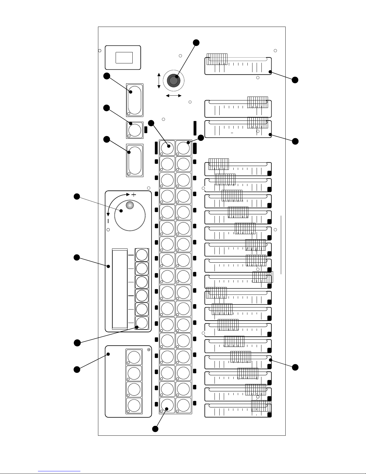
2. TOP PANEL VIEW
2
11
4
6
5
9
10
5
6
7
8 9
10 11 12
13
14 15 16
2
1
3
4
14
13
1
12
8
Page 5

3. TOP PANEL DESCRIPTION.
JOYSTICK
Its proportional function allows for precise
setting of mirrors or moving heads. Pressing
on the joystick activates default (center pan
and tilt) mirror position.
11
12
16 faders used to control 16 DMX channels of
the selected fixture.
Minimum = 0,
Maximum = 255
FADERS
CONTROLING
FIXTURE
FUNCTIONS
X-FADE AND RATE
CONTROL FADERS
These two faders control program playback
parameters in the auto mode. The RATE
fader sets program rate (speed) i.e. duration
of the scene. The X-FADE fader controls the
amount of crossfade between scenes.
Minimum = 0 crossfade
Maximum = full crossfade
13
MASTER
Controls the fade function of active fixtures.
14
10
Used to select the second bank of programs
or fixtures.
BANK SELECTOR
(33-64)
Used to select the function of the 32
PROGRAM / FIXTURE buttons.
PROGRAM /
FIXTURE
SELECTOR
9
Show playback button. Also used to record
TAP rate.
Sends blackout command to all fixtures.
LCD menu function buttons.
MENU FUNCTION
BUTTONS
Four buttons controlling programming
functions.
PROGRAMMING
SECTION
Records in controller's memory all new
programs, configurations, etc.
Encoder wheel. Controls applicable menu
functions.
ENCODER WHEEL
48 character alphanumeric LCD.
LCD DISPLAY
32 buttons used to activate programs or
fixtures. Their function is selected with the
PROGRAM / FIXTURE SELECTOR button.
PROGRAM /
FIXTURE BUTTONS
"SHOW"
BUTTON
6
BLACKOUT
BUTTON
7
2
1
"ENTER"
BUTTON
5
4
3
8
3
Page 6
4
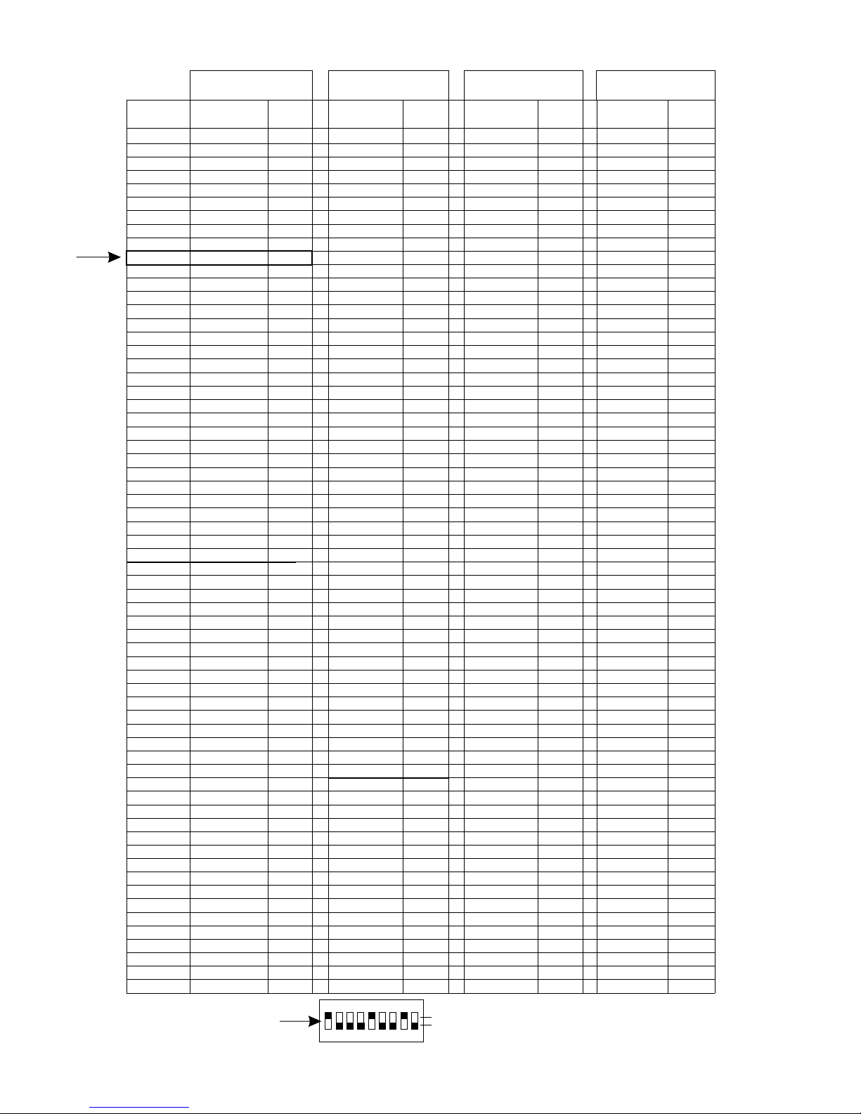
4. DMX ADDRESS TABLE
0
1
ON DIP
54321 9876
EXAMPLE
DMX Address = 145
1
2
3
4
5
6
7
8
9
10
11
12
13
14
15
16
17
18
19
20
21
22
23
24
25
26
27
28
29
30
31
32
33
34
35
36
37
38
39
40
41
42
43
44
45
46
47
48
49
50
51
52
53
54
55
56
57
58
59
60
61
62
63
64
DIP SW
MODE 1
MODE 2
MODE 3
MODE 4
100000000
100010000
100001000
100011000
100000100
100010100
100001100
100011100
100000010
100010010
100001010
100011010
100000110
100010110
100001110
100011110
100000001
100010001
100001001
100011001
100000101
100010101
100001101
100011101
100000011
100010011
100001011
100011011
100000111
100010111
100001111
100011111
Button #
100000000
100100000
100010000
100110000
100001000
100101000
100011000
100111000
100000100
100100100
100010100
100110100
100001100
100101100
100011100
100111100
100000010
100100010
100010010
100110010
100001010
100101010
100011010
100111010
100000110
100100110
100010110
100110110
100001110
100101110
100011110
100111110
100000001
100010001
100001001
100011001
100000101
100010101
100001101
100011101
100000011
100010011
100001011
100011011
100000111
100010111
100001111
100011111
100000000
100100000
100010000
100110000
100001000
100101000
100011000
100111000
100000100
100100100
100010100
100110100
100001100
100101100
100011100
100111100
100000010
100100010
100010010
100110010
100001010
100101010
100011010
100111010
100000110
100100110
100010110
100110110
100001110
100101110
100011110
100111110
100000001
100100001
100010001
100110001
100001001
100101001
100011001
100111001
100000101
100100101
100010101
100110101
100001101
100101101
100011101
100111101
100000011
100100011
100010011
100110011
100001011
100101011
100011011
100111011
100000111
100100111
100010111
100110111
100001111
100101111
100011111
100111111
100000000
101000000
100100000
101100000
100010000
101010000
100110000
101110000
100001000
101001000
100101000
111101000
100011000
101011000
100111000
101111000
100000100
101000100
100100100
101100100
100010100
101010100
100110100
101110100
100001100
101001100
100101100
101101100
100011100
101011100
100111100
101111100
100000010
100100010
100010010
100110010
100001010
100101010
100011010
100111010
100000110
100100110
100010110
100110110
100001110
100101110
100011110
100111110
100000001
100010001
100001001
100011001
100000101
100010101
100001101
100011101
100000011
100010011
100001011
100011011
100000111
100010111
100001111
100011111
1
17
33
49
65
81
97
113
129
145
161
177
193
209
225
241
257
273
289
305
321
337
353
369
385
401
417
433
449
465
481
497
1
9
17
25
33
41
49
57
65
73
81
89
97
105
113
121
129
137
145
153
161
169
177
185
193
201
209
217
225
233
241
249
257
273
289
305
321
337
353
369
385
401
417
433
449
465
481
497
1
9
17
25
33
41
49
57
65
73
81
89
97
105
113
121
129
137
145
153
161
169
177
185
193
201
209
217
225
233
241
249
257
265
273
281
289
297
305
313
321
329
337
345
353
361
369
377
385
393
401
409
417
425
433
441
449
457
465
473
481
489
497
505
1
5
9
13
17
21
25
29
33
37
41
45
49
53
57
61
65
69
73
77
81
85
89
93
97
101
105
109
113
117
121
125
129
137
145
153
161
169
177
185
193
201
209
217
225
233
241
249
257
273
289
305
321
337
353
369
385
401
417
433
449
465
481
497
DMX
addr
DIP SW
DMX
addr
DIP SW
DMX
addr
DIP SW
DMX
addr
Page 7
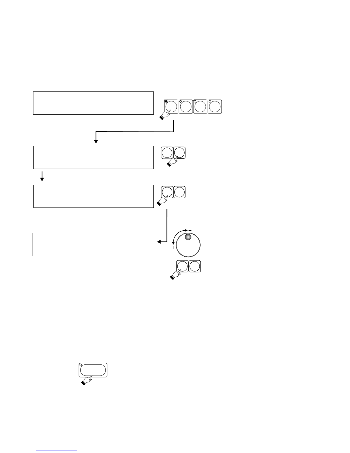
5. SET-UP / CONFIGURATION
NOTE !
Access to these functions may be blocked. See SERVICE MODE..
5
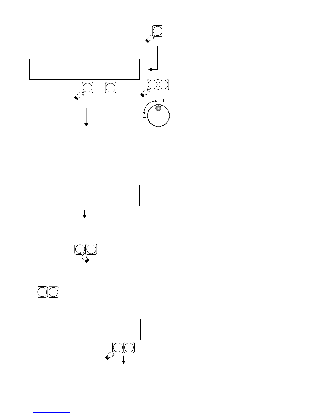
Select program...
With the "Select program.."
screen being displayed on the
LCD, press CONFIG in the
programming section. LCD will
change to the following screen
and the CONFIG LED will light up.
Ch. Assign Mode
I ( 1 ) Fixtures
Special
fnctns
!! Clear all programs !!
Continue? Yes No
A B
NOTE !
Changing DMX address mode will erase all
programming. Choose appropriate mode
before doing any programming.
Ch. assign mode : model
32 fxtr x 16 channels
Using the encoder or buttons E or F select
desired mode.
E F
E F
MIDI
CONFIG SHOWS
SCENES
5.1. DMX ADDRESS MODE
Press A or B button.
Choose appropriate DMX address mode , according to the type of fixtures ( scanners ) used.
1 - 32 x 16 channels
2 - 32 x 8 channels + 16 x 16 channels
3 - 64 x 8 channels
4 - 32 x 4 channels + 16 x 8 channels + 16 x 16 channels
ENTER
There are 4 DMX address modes.
Press ENTER button after choosing the desired mode. New
settings will be recorded in controller’s memory.
Page 8
Select fixtures to be assigned from the fixture library. They will be assigned to fixture buttons.
NOTE !
Setting DMX address on the fixtures will depend on DMX address mode previously selected. Consult DMX
ADDRESS TABLE on page 4.
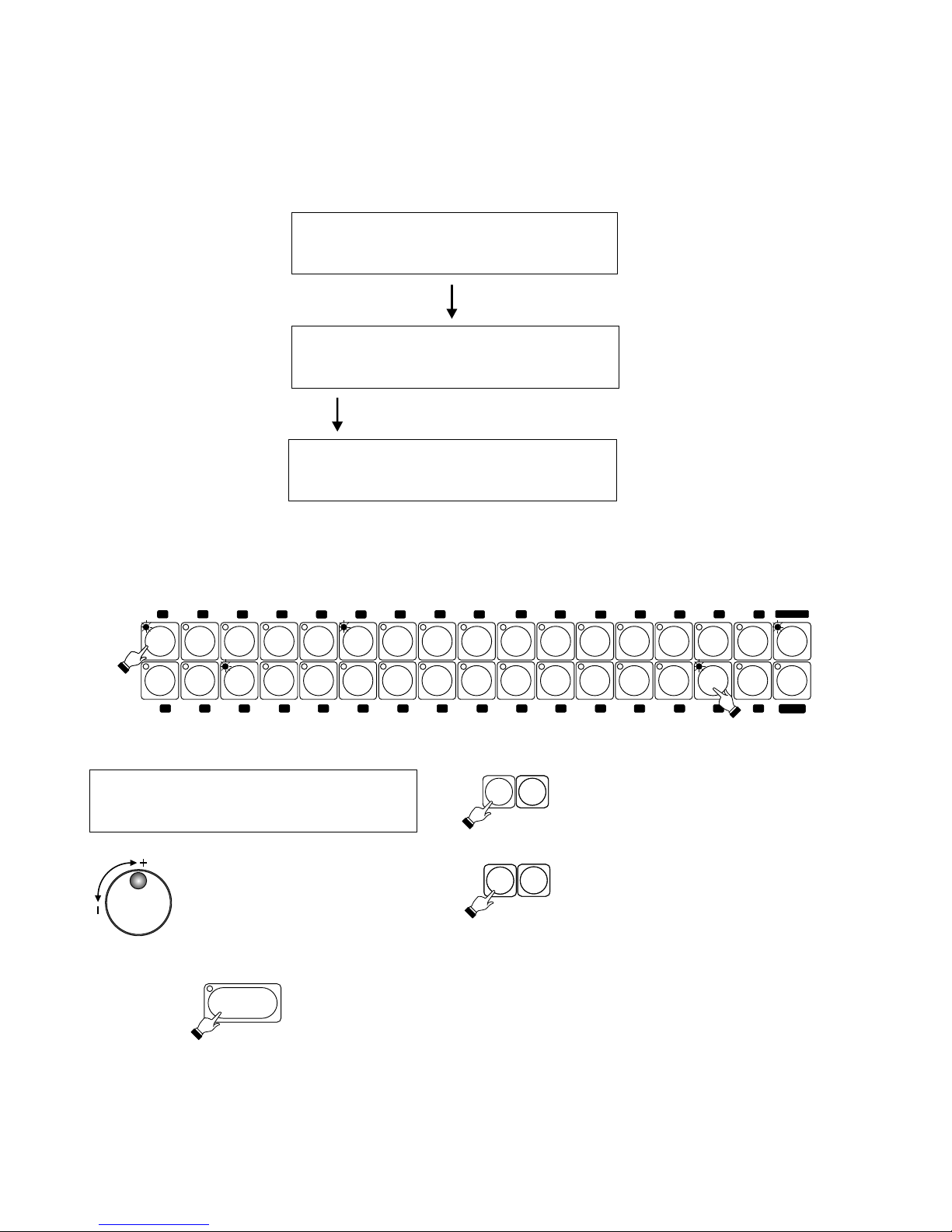
5.2. ASSIGNING FIXTURES
5.2.1. FIXTURE MODELS
Select fixtures:
( 1-32 ) review OK
Fixtures:
Models
Dip
switch
DMX
delay
Press fixture button ( s) to which you want to assign the fixture. Fixture LED will light up and a brand / fixture
model screen will appear on the LCD display.
Martin Mac 250
- + - +
Once you have selected the desired fixture, press ENTER button.
Fixture LED will go off , and fixture assignment will be saved in the
memory.
Press A or B to scroll through the
alphabetical fixture brand list.
Press D or E to scroll through the
alphabetical listing of fixture models.
Use the encoder to scroll
through the complete fixture
library.
A B
D
E
ENTER
33
2
34
3 35 4
36
5
37
6
38
7 8
40
10 42
114312
44
13 45
14
46
15 47 16
48
1
3
6
41
6
18
50
20
52
215322
54
23
55
24
562557
26
58
27
28
60
30
62 31 63 32 64
17 4
6
61
2
6
5
6
51
1
6
33 - 64
Assign other fixtures in the same manner
6
Ch. Assign Mode
I ( 1 ) Fixtures
Special
fnctns
PROGRAM
FIXTURE
Page 9
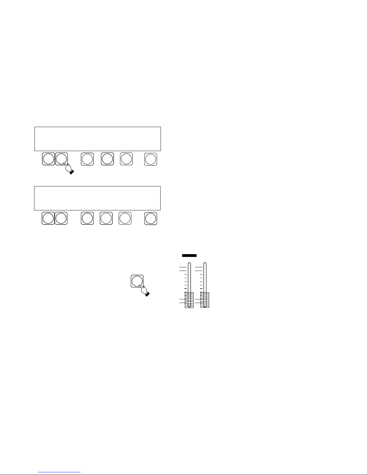
Press D to enable the review of assigned
fixtures function.
Press E (Clr.) to remove the displayed fixture
(Martin Mac 250 for ex.) from all program(s)
were it was used.
Martin Mac 250
6 - + Del. Clr. OK
Press B or C , or use the encoder to scroll
through all assigned fixtures. The LCD will
show name / model of the fixture. Below it a
fixture number will appear. At the same time
fixture LEDs will light up. A blinking fixture LED
indicates that the fixture is assigned to the
second fixture bank, i.e. 33 - 64.
D
Press D to cancel
fixture assignment.
D
CB
7
E
Not assigned !
6 - + Del. Clr. OK
With A or B select one of the assigned fixtures.
The LCD will show proper dip switch setting for
that fixture.
0 = OFF 1 = ON
C
D
A
B
5.2.2. DIP SWITCH SETTINGS
Fxtr 1 addr 100010000
- + = 17 back
Press C or D.
5.2.3. DMX DELAY
Delay = 0
- + back
The DMX DELAY function allows slowing down of the
DMX signal to match the "receive" speed of the fixture.
The DMX DELAY settings are 0 to 7.
E
F
DIP SWITCH SETTING - indicates correct dip switch
settings of assigned fixtures.
Press CONFIG in the programming section (see
page 5). With the screen shown on the left press C or
D under "Fixtures".
Select fixtures:
( 1-32 ) review back
Ch. Assign Mode
I ( 1 ) Fixtures
Special
fnctns
Fixtures:
Models
Dip
switch
DMX
delay
Fixtures:
Models
Dip
switch
DMX
delay
Page 10

Reset : select fixtures
All Cancel Execute
Setting these functions is not essential for proper operation of the console, They offer, however , some
helpful options.
FIXTURE RE-SET - Many fixtures on the market have the re-set capability , that is they can be re-set without
being turned off. Often this feature can be quite cumbersome. That is why an easy to access re-set function
has been incorporated in the controller.
TRIGGERING PROGRAMS WITH FADERS. - Groups of 16 programs may be triggered with faders. This
function lets the user choose which group of programs will be triggered with faders as well as buttons.
Select fixtures to be re-set by pressing
corresponding fixture buttons. Their LEDs will
light up. Then press E or F. The controller will send
a re-set command to selected fixtures. To re-set
all fixtures press A or B.
To cancel re-set press C or D,
NOTE !
The re-set procedure may take some time.
5.3.2 TRIGGERING PROGRAMS WITH FADERS
Using the encoder choose the group of
programs to be triggered with faders..
1. ( 1 - 16 )
2. ( 17 - 32 )
3. ( 33 - 48 )
4. ( 49 - 64 )
5. None.
Press ENTER to save, and then
press F to exit the function.
E F
5.3. SPECIAL FUNCTIONS
5.3.1. FIXTURE RE-SET.
Press A or B.
A B
8
E F
Press E or F.
Bank select ( 1 - 16)
- + back
Press E or F.
Fixtures:
Assign
faders
Reset
Fixtures:
Assign
faders
Reset
Ch. Assign Mode
I ( 1 ) Fixtures
Special
fnctns
Page 11

9
6.1. PROGRAMMING STANDARD SCENES
Pgm: 01 Scene 01 [ . . 0 ]
Pgm: 05 Scene 03 [ 137 ]
Pgm: 12 Scene 13 [ 255 ]
- + - + ED
- + - + ED
- + - + NW E
With the following screen
showing on the LCD press
SCENES in the programming
section. The PROGRAM /
FIXTURE LED will light up.
NOTE !
All LEDs in the fixture /
program section have to be
off.
A B
C
D
E
F
F
D
E
A B
The controller will call up program 1 scene 1 and set the
fixtures according to scene 1 settings. With the fixture
buttons select fixture(s) to be programmed. Adjust the
settings with the joystick and the faders. The ENTER LED
will light up indicating new settings. To cancel new settings
turn the fixture LEDs off. To CONFIRM them press ENTER.
E
To copy a scene to another scene or to another scene in
another program press E to change thje command from ED
( edit ) to NW ( new ). Then with A or B select the program
number and with C or D select the number of the scene
to be copied to. Programs may also be selected with the
encoder. Adjust fixture settings with the faders and the
joystick, and press ENTER to record the new scene.
Value of the last fader setting.
Each program may contain up to 24 scenes. If a program
has less than 24 scenes press F and then ENTER to record
the last scene. An ”E” will appear on the LCD above the F
button.
Recorded programs may be viewed and edited. The
controller should be in the edit mode - “ED” above the E
button. Press E to toggle between ED and NW
MIDI
CONFIG SHOWS
SCENES
6. SCENE PROGRAMMING.
Pgm: 05 Scene 03 [ 137 ]
- + - + ED S
E
There are 2 modes of scene programming : standard and
special
Select program ...
Press A or B to select the standard mode. Press D to select
the special mode ( page 10 )
Use the delete function ( E ) to delete previously recorded
programs. Select program to be erased and confirm by
pressing ENTER. (see 6.3)
NOTE !
This function may be blocked.
Consult SERVICE MODE section.
Scene Programming
Standard Spec. Del. OK
NOTE!
All programs containing special scenes (see 6.2.) are
denoted by "S" appearing in the bottom right hand corner.
Page 12
10
6.2. PROGRAMMING SPECIAL SCENES
The internal effects generator contains following movements : figure 8 , circle and diagonal. Special scene
programming incorporates assigning one of those movements to a selected program, and defining
parameters such as speed, diameter, and location of the center of the movement.
NOTE !
Special scene programming may only be done in programs 49-64.
NOTE!
To avoid conflict during playback of different programs controlling both scanners and dimmers, the PAN and
TILT setting should be set at neutral (128). This is done by pressing the joystick.
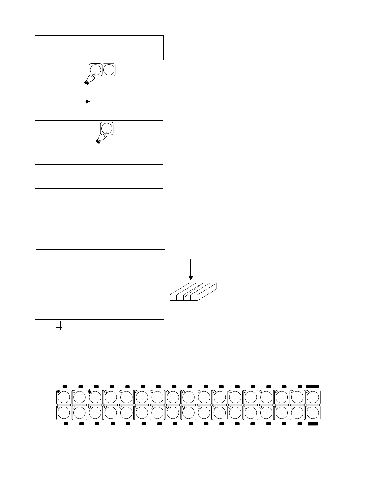
In programming different movements for a number of
fixtures it is important to know the start of the program.
Press D to activate start synchronization.
To program movement in opposite directions in the same program :
1. Select fixtures that are to move to the right
2. With the C button select O+ on LCD display..
3. Adjust speed and diameter.
4. Turn off fixture LEDs. The fixtures will continue their movement.
5. Select fixtures that are to move to the left.
6. With the C button select O- on the LCD display.
7. Adjust speed and diameter..
8. Press ENTER to record all the settings.
With C select following effects :
O+ - circle to the right
O - - circle to the left
8+ - 8 to the right
8- - 8 to the left
/+ - diagonal to the right
\- - diagonal to the left
C
Press A or B to select the program.
Select fixture(s) to be programmed by pressing
corresponding fixture buttons.
NOTE!
Each program may control up to 64 fixtures.
Set faders DIAMETER and RATE ( speed ) at 0.
NOTE!
Press E (Del) to delete any DMX values previously set
in the selected program.
Set diameter and rate (speed)
faders. Set the center of the
movement with the joystick.
Save all changes by pressing
ENTER.
DIAMETER
C
C
A B
A B
E
E
F
F
X: 0 Y: 0 D: 52 Rt: 8.1
Select fixtures
Pgm. 49 8+ ! Del. ED
Pgm. 49 8+ ! Del. ED
D
D
X
F
A
D
E
R
A
T
E
Page 13

7. MIDI PROGRAMMING
6.3. DELETING PROGRAMS
With the "Select program" screen
displayed on the LCD, press MIDI
in the programming section. The
MIDI LED will light up and the
following screen will appear.
Select note: 60
MIDI assignments
Set. Delete
and key : synchro No
Press A to enable assigning program buttons to MIDI
generated notes.
A
MIDI
CONFIG SHOWS
SCENES
When al l MIDI assignments are
completed press ENTER ( LED will go off )
to record the settings in the memory.
E
Press E after selecting the MIDI note to set program
synchronization mode.
Select note: 60
and key : ( S ) No
11
Select note:
Select note: 60
No
and key : ( S ) No
Select and press a MIDI note that you want to trigger one
of the programs with.
Select and press program button to be triggered with the
MIDI note.
Select note: 60
and key : 1 ( S ) OK
F
ENTER
Press F to confirm. Select another MIDI note and a program
to be triggered by it. Confirm by pressing F.
Select program ...
A B
D
F
E
Program 1 - erased
- + delete OK
To delete a program press SCENES (In
PROGRAMMING SECTION), press E (Del.), and
select the program to be deleted by pressing A or B.
Then press D to delete the program.
Press ENTER to confirm.
Page 14
Note 60 key 15
No notes assigned
prev next. delete OK
OK
7.1. CANCELLING MIDI ASSIGNMENTS
7.2 TRIGGERING PROGRAMS WITH MIDI
To cancel MIDI assignments press C or D.
After clearing all assignments a “No notes assigned”
screen will appear on the LCD.
Select program...
Press previously assigned MIDI
note to trigger selected program.
auto 44 12,4 Set.
1 3 All
33
2
34
3 35 4
36
5
37
6
38
7 8
40
10 42
114312
44
13 45
14
46
15 47 16
48
1
3
6
41
6
18
50
20
52
215322
54
23
55245625572658
27
28
60
30
62 31 63 32 64
17 4
6
61
2
6
5
6
51
1
6
33 - 64
The LCD will show the numbers of triggered programs.At
the same time program LEDs will light up. Each program
can be turned off by pressing the corresponding MIDI note
again, or by pressing the program button.
D
C
D
12
Press A or B to scroll through all MIDI assignments. Press D
to delete an assignment. Next assignment will appear on
the LCD.
MIDI assignments
Set. Delete
PROGRAM
FIXTURE
Page 15

8. PROGRAMMING A SHOW
MIDI
CONFIG SHOWS
SCENES
F
New s creen will appear ( as shown ) on the LCD. .With A
or B select the show number , and with C or D the step
number. With the program buttons select programs to be
included in the first step of the show.
Press E to select NW ( new show programming ) or ED
( review and editing of previously recorded show ).
Start 0,00.0 Time: 0,00.0
Show 1 Step 1 ED
Start 0,00.0 Time: 1,36.7
Start 0,00.0 Time: 4,13.7
Show 1 Step 1 ED
Show 1 Step 1 ED E
CED
A B
The clock indicates the time
elapsed from the beginning of
the show.
Each show may consist of up to 256 steps. If the show
has less than 256 steps , press F before pressing
ENTER to record the last step.
13
With the "Select program ..."
screen showing on the LCD
press S H OWS in th e
programming section.
NOTE !
All LEDs should be off in the
fixture / program section.
A show is a sequence of programs linked together. Each show
may consist of up to 256 steps. Each step may contain up to 7
programs.
NOTE !
This function may be blocked.
Consult SERVICE MODE section.
ENTER
With the encoder set the time from the
beginning of the show , when the
programs included in the first step are to
be triggered.
Setting next step number automatically
sets the end time for the previous step,
and the start time for the next step.
Press ENTER to record the step in the
memory.
Select program ...
Page 16

auto 44 12,4 set.
1 3 9 11 33 45 63 All
33
3 35
1
34
Set the position of the cursor with the
encoder. Lower line of the LCD shows
program synchronization information , of
the highlighted program.
To change synchronization parameters
press F.
auto 44 12,4 canc OK
Synchr. X-F Rate Pgm: 15
auto 44 12,4 canc OK
manual 2 canc OK
audio canc OK
MIDI canc OK
Synchr. X-F Rate Pgm: 15
Synchr. Scene Pgm: 15
Synchr. Pgm: 15
Synchr. Pgm: 15
Pl ay ba c k o f p ro gr am s i s
controlled by the internal clock.
Its parameters are rate in
seconds, and crossfade ( X-F ) in
%. They can be adjusted with the
RATE and X-FADE ( crossfade )
faders.
C D
Press C or D to control the
program manually , one scene at
a time ( forward or backward ).
The program is controlled by audio , through the
audio input at the back of the console.
NOTE !
Adjust audio sensitivity at the back of the
console. This will assure proper audio
synchronization.
The program is controlled through MIDI , by an
external MIDI controller. See detailed MIDI
instructions on page 10.
Up to 7 programs may be played back
simultaneously. Programs are played back
by pressing program buttons. To trigger
programs 33 - 64 press the “33 - 64” button
in the program button section. A flashing
program LED indicates the program is in
the other bank.
Press A or B to choose synchronization mode.
9. PROGRAM PLAYBACK
A B
14
To confirm settings for each program press F or press E to cancel. Then with the cursor select the next
program and adjust its parameters. When the parameters for all programs are set press ENTER to record the
settings in the memory..
NOTE !
By turning the program off ( program LED off ) before pressing ENTER , previous setting will be retained.
Select program ...
X
F
A
D
E
R
A
T
E
Program version : 1.10
Library : 1. 0 OK
Page 17

auto 44 12,4 set
1 3 9 11 33 45 63 All
It is possible to manually adjust active ( i.e. Fixtures which are being controlled by a program ) fixtures.
For example to change color or gobo , or to change mirror positioning.
9.2. MANUAL CONTROL OF ACTIVE FIXTURES,
15
31 63 32 64
33 - 64
15 47 16
48
Activate fixtures to be manually adjusted by pressing corresponding fixture buttons. Adjust fixture
settings using the joystick and the faders. Continue with other fixtures as necessary.
33
2
34
3 35 4
36
5
37
6
38
7 8
40
10 42
114312
44
13 45
1
3
6
41
6
18
50
20
52
215322
54
23
552456
25
572658
27
28
60
30
62
17 4
6
61
2
6
5
6
51
1
6
14
46
31 63 32 64
33 - 64
15 47 16
48
With the programs running ( display shown ) , press
PROGRAM / FIXTURE. As long as the PROGRAM /
FIXTURE LED is on, the 32 buttons control fixtures, not
programs.
With the cursor select the program and press F, to
enter the rate adjust mode. To set the same tap rate for
all programs set the cursor at "All".
Tap the TAP button 4 times to set the rate. The tap
button LED will start flashing .
To cancel the previous setting and set the new one
press and hold the TAP button for 2 seconds and tap 4
times again.
To return to previous tap setting, press E (cancel)
Press F to go back to previous screen. Adjust other
programs as needed.
Press F and then ENTER to record the new rate(s).
Program rate (speed) may also be set manualy with the TAP / SHOWS button. The TAP rate may be set for
one or more programs, depending on program selection
auto 44 12,4 set
1 3 9 11 33 45 63 All
auto 44 12,4 canc OK
Synchr. X-F Sz. Pgm: 15
9.1. SETTING TAP RATE
ENTER
BLACKOUT
SHOWS
TAP
cursor
E
F
PROGRAM
FIXTURE
PROGRAM
FIXTURE
Page 18

Programs may be triggered with both buttons and faders.
The console has to be set-up for fader triggering. See the
SET-UP / CONFIGURATION section.
S
T
A
T
I
O
N
A
R
Y
G
O
B
O
R
O
T
A
T
I
N
G
G
O
B
O
33
2
34
3 35 4
36
5
37
1
18
50
20
52
21
53
17 4
6
51
1
6
S
T
R
O
B
O
/
F
A
D
E
T
I
L
T
C
O
L
O
R
Select program ...
auto 44 12,4 set
36 All
9.3. TRIGGERING PROGRAMS WITH FADERS
NOTE !
These functions may be blocked.
Consult SET-UP / CONFIGURATION
Section.
Raising a fader will trigger corresponding program. The
program LED of the program being triggered will light up ,
and the LCD will show its number. The fader controls all
fade functions in the program which have been enabled.
The program turned on with the fader may be turned off
with its button. Conversely, a program turned on with its
button may be turned off with t he fader.
- Press PROGRAM / FIXTURE ( LED flashing ).
- Adjust selected fixture (s) with the joystick or faders.
- Activate other programs as desired ( program LEDs will NOT
light up.
- To "Solo " a particular program , press and hold its button for 1
second. All other programs will be turned off. Manual control of
fixtures remains active.
- To return to program select and edit functions , press and hold
the PROGRAM / FIXTURE button for 1 second. ( LED off ).
31 63 32 64
33 - 64
15 47 16
48
Pressing PROGRAM / FIXTURE button again ( LED flashing ) allows simultaneous manual control of the
fixture as well as activation of other programs.
FIXTURE
PROGRAM
16
Page 19

10. SHOW PLAYBACK
17
Select program ...
E
E
F
F
It is possible to synchronize your light show with music playback by using a CD player with remote start
capability. Pressing E to start the show will automatically start the CD player. The synchronization accuracy
is 0.1 second.
With the screen shown on the left press the SHOWS
button located beside ENTER.
Step 1 Time 0,00.0
Show 1 - + Start
Step 1 Time 0,00.0
Show 1 - + Start P
Step 1 Time 0,00.0
Show 1 - + Start P
C
D
During show playback the program LEDs light up ,
indicating which program is currently being played back.
With C or D select show number.
33
2
34
3 35 4
36
5
37
1
18
50
20
52
21
53
17 4
6
51
1
6
Press E to start or stop the show at any time. Press F to
pause. That will automatically stop the CD as well.
Press E to start or stop the show playback. Press F to
pause.
During show playback the LCD displays current step # ,
and time elapsed from the beginning of the show.
Program version : 1.10
Library : 1. 0 OK
Page 20

A
11. SERVICE MODE
The service mode incorporates following functions - change of password , downloading new software
releases , blocking access to functions , and confirmation of payment.
NOTE !
All functions of the controller are disabled when the service mode is being accessed.
Th e controller is equipped with a standard RS232 port , allowing the controller to be hooked
up to a PC. The port is used to download new
software releases and new fixture libraries. It
can also be used to offload controller’s
memory onto a PC. This allows the user to
save and archive programming onto floppy
diskette. Programming done on a PC can also
be transferred into controller’s memory. A
program allowing communication between the
controller and a PC is included with the
controller.
Password set-up. The password locks out
access to the service mode..
Payment confirmation.
The controller can be supplied from the
manufacturer with a password and a time limit.
Once full payment is received by the
manufacturer , the user will be supplied with a
password to confirm the payment. Otherwise
the unit will stop functioning once the time limit
has been exceded.
System restart.
Programming lockout.
Configuration lockout.
Configuration lock
System restart
A B E F
C
D
Next screen.
Previous screen.
Command
confirmation.
18
With the shown screen displayed on the LCD ,
tap A. This is the first screen to appear upon
turn on.
NOTE !
Service mode can only be accessed from
this screen.
Px 102 Nadir versjon 1.10
Proxima s.c.
User password change
next. prev. Enter
User password change
next. prev. Enter
Payment confirmation
next. prev. Enter
next. prev. Enter
next. prev. Enter
Programming lock
next. prev. Enter
Page 21

Waiting ....
OK
11.1. PC INTERFACE AND PROGRAMMING
Switch on the PC and open a new folder ( “Nadir “ ) in My Documents. Then copy program “nadir.exe” from
the supplied diskette into the new folder.
Turn on the controller and access the service mode.
Select the screen below.
NOTE !
Blinking fixture LEDs on the controller indicate
transmission of data between the controller and the
PC. Once your work has been completed and the
flashing stops , press F twice.
E F
19
Press E or F.
PC comunication
Connect COM 1 or COM 2 on your PC with the RS-232 port on tne controller , using cable supplied with the
unit.
NOTE !
Both the PC and the controller should be switched off.
In the program menu on your computer screen select
“Action “. You can now download new fixture libraries , new
programming, as well as read and create new programs.
next. prev. Enter
Page 22

Enter user password :
** _ OK
Re-enter password :
** _ OK
Password changed !
OK
11.2. USER PASSWORD SET-UP
Press E or F. A new screen will appear , and you will be able
to enter your password.
33
2
34
3 35 4
36
5
37
6
38
7 8
40
10 42
114312
44
13 45
14
46
15 47 16
48
1
3
6
41
6
18
50
20
52
215322
54
23
55245625572658
27
28
60
30
62 31 63 32 64
17 4
6
61
2
6
5
6
51
1
6
Enter the password by pressing fixture buttons. The
password contains 8 characters , that is 8 buttons have to
be pressed. Not entering any characters and pressing OK
will erase previous password.
Once the password has been entered , only the password
holder will be able to access the service mode.
Payment confirmed !
OK
11.3. PAYMENT CONFIRMATION.
Press E or F. A new screen will appear , allowing the
operator to enter payment confirmation code supplied by
the manufacturer.
Enter payment conf. code
**_ OK
Enter the code by pressing fixture buttons.”
Entering the code enables continued functioning of the
controller.
20
E F
E F
User password change
next. prev. Enter
Payment confirmation
next. prev. Enter
Page 23

Configuration lock OFF
Program lock OFF
Change Enter
Change Enter
11.4. PROGRAMMING AND CONFIGURATION LOCKOUT.
The upper line of the display shows current status. Press B
to toggle lockout on & off. Press F to confirm the entry.
B
B
NOTE !
Configuration lockout disables the CONFIG button in the programming section.
Programming lockout disables all buttons in the programming section.
SHOWS
PROGRAMMING
MIDI
CONFIG
SCENES
Programming lockout disables all buttons in
this section.
Configuration lockout disables only the
KONFIG button in this section.
21
E F
F
E F
F
Press E or F to access configuration lockout function.
The upper line of the display shows current staus. Pressing
B will toggle the lockout on & off. Press F to confirm the
entry.
With the shown screen on the LCD press E or F to access
programming lockout function.
Programming lock
next. prev. Enter
Configuration lock
next. prev. Enter
Page 24

12. CONNECTING THE FIXTURES TO THE CONTROLLER
The controller transmits a standard DMX -512 signal. To assure proper functioning of the system , dip
switches on the fixtures must be set properly. Also appropriate cabling setup must be used. Here are some
practical suggestions.
1. A microphone type cable should be used , that is , two-conductor with a shield.
2 All XLR connections should be done in the following manner.
pin 1 = shield pin 2 = DMX- pin 3 = DMX+
3. The controller and the fixtures must be connected in series , that is, the output of the controller is
connected to the input of the first fixture , the output of the first fixture is connected to the input of the second
fixture , the output of the second fixture is connected to the input of the third fixture etc. .
4. A 100 Ohm resistor MUST be installed at the output of the last fixture , between pins 2 and 3. This is
commonly called DMX TERMINATION.
5. Set dip switches on the fixtures according to the table on page 4.
NOTE !
Martin fixtures have pin 2 and pin 3 reversed. A “reversed” cable should be used so they may function
correctly.
22
RS 232
13. BACK PANEL VIEW
Power input.
The AC adapter is supplied with the unit.
RS-232 I/O
Computer Interface
MIDI Jacks
MARTIN
MARTIN
OTHER
FIXTURE
OTHER FIXTURE
CONTROLLER
1
1
1
2
2
2
3
33
DMX -
DMX +
1
2
3
1
2
3
SHIELD
SHIELD
SHIELD
SHIELD
DMX -
DMX -
DMX +
DMX +
1
2
3
1
2
3
1
2
3
1
2
3
DMX -
DMX +
TERMINATION
100 Ohm
CD Control Signal
MINI JACK
Audio Input
Stereo Jack
Audio sensitivity
adjustment.
LCD Contrast Adjustment
DMX OUT
MIDI
IN
OUT
AUDIO
775 mV
PWR
9V AC / 12 V DC
LCD
CONTRAST
CD
CONTROL SIGNAL
AUDIO
SENSITIVITY
Page 25

512
1536
64
8 (up to 256 steps each)
8 Mb
0 dB
STEREO 1/4'' JACK
5-pin DIN
9-pin D-SUB
MINI JACK
3-pin XLR
5-pin DIN
9-pin D-SUB
12V DC or 9V AC
10 VA
5 kg
483mm (19")
221mm (standard 5U)
85mm
- DMX channels
- scenes
- programs
- shows
- memory
- audio signal level:
- input:
- audio 0 dB
- MIDI
- RS 232
- audio
- output:
- DMX 512
- MIDI
- RS 232
- power
- power consumption
- weight
- dimensions:
- width
- depth
- hight
23
STERO JACK
MIXER
CD
MINI JACK
MINI JACK
JACK
start
!!! NOT Conneced!!!
stop
MINI JACK
CD Control
Ground
Audio signal
!!!NOT Connected !!!
stereo jack
AUDIO
RCA
cable
ŚREDNICA
WYCIEMNIANIESEKWENCJE
ZAPAMIĘTAJ
SEKW
SKANER
G
O
B
O
S
T
A
Ł
E
G
O
B
O
O
B
R
O
T
O
W
E
O
B
R
O
T
Y
G
O
B
O
P
R
Y
Z
M
A
T
O
B
R
O
T
Y
P
R
Y
Z
M
A
T
U
F
I
L
T
R
O
S
T
R
O
Ś
Ć
I
R
Y
S
P
O
W
I
Ę
K
S
Z
E
N
I
E
K
O
L
O
R
2
K
O
L
O
R
3
P
Ł
Y
N
N
O
Ś
Ć
S
Z
Y
B
K
O
Ś
Ć
TAKT
WYBÓR FUNKCJI
5
6 7 8 9
10 11 121314 15 16
33
2343 35 4365376387 8
40
10 42
114312
44
13 45
14
46
15 47 16
48
1
3
6
41
6
I
N
N
E
18
502052
215322
54
23
55245625572658
27
28
60
30
62 31 63 32 64
17 4
6
61
2
6
5
6
51
1
6
33 - 64
Nadir Px102 wer. 1.3
gotowy do pracy
OK
8
CENTRUM
ZASILANIE
Nadir
PX 102
POZIOMO
PROGRAMOWANIE
MIDI
KONFIG
SCENY
P
I
O
N
O
W
O
S
T
R
O
B
O
/
J
A
S
N
O
Ś
Ć
S
U
M
A
2
1
3
4
P
I
O
N
O
W
O
K
O
L
O
R
A B C D E F
14. TECHNICAL SPECIFICATIONS
Page 26

FAQ
24
Page 27

NOTE
25
 Loading...