

Page 1

Floorstanding cast iron boiler
Cascade conection possible
Output up to 150 kW
Grizzly
EN
verzion
XXXX - v.2 4/2005
Manual for instruction
and use of boiler
65, 85, 100, 130, 150 KLO
Protherm spol. s r.o.
Jurkovičova 45
909 01 Skalica
Tel.: 034 6966 101
Fax: 043 6644 017
www.protherm.sk
Page 2

2
3
Dear Client,
You have just become an owner of a KLO /
KLO EKO (Grizzly) natural gas or propane gas fired cast iron boiler. We are confident that you will be satisfied with the
service this boiler will give you. However, you’ll have to comply with at least
minimum requirements when running
the equipment. Therefore please read
these Operating Instructions carefully
and comply with their guidelines.
Please pay careful attention to the following
important information:
1. The boiler with all its accessories must
be installed and used in accordance
with an installation design, all applicable
legal regulations, technical standards
and manufacturer’s instructions.
2. The boiler may be installed only in the
environment for which it has been designed and only in a correctly ventilated
room.
3. After installation, the boiler must be put
into operation by a service organisation
authorised by the manufacturer.
4. Please also contact authorised service
if you are experiencing any problems
with the equipment – unauthorised repairs may damage the boiler (as well as
the connected equipment!).
5. The service technician when putting
the boiler into operation for the fist time
must demonstrate its controls and show
you its various parts and how to control
them.
6. Check whether the boiler is complete.
7. Check whether it is the model you have
ordered.
8. Whenever you have any doubts how to
operate the boiler, find and study the
relevant information in these Operating
Instructions and proceed in accordance
with them.
In practice, situations might occur when the
following essential measures have to be
taken:
– prevent the boiler from being (even
accidentally) switched on while inspecting the fumes exhaust and gas
and water distribution routes, by disconnecting the boiler from power
supply by another means than just
with the boiler’s switch (e.g. by pulling the power cord plug out of the
socket),
– shut the boiler down every time when
flammable or explosive vapours are
present (even temporarily) inside
the premises from which combustion air is supplied to the boiler,
– if it is inevitable to drain water from
the boiler or the heating system, the
water must not be dangerously hot,
– when water leaks from the boiler’s
heat exchanger or when the exchanger is clogged with ice, do not try to
switch the boiler on until normal running conditions have been restored,
– during (even suspected) gas leaks or
after gas supply failure, switch the
boiler and the gas supply off and call
the gas company or authorised service.
Regulations and Directives
The PROTHERM KLO boiler may be
put into operation only by an authorised
service organisation in accordance with
UBP SR Notice No. 74/1996. Installations,
putting the boiler into operation, warranty
and post-warranty service are performed
by a network of the manufacturer’s contractual service organisations, which meet
the above-specified requirements. Installations must be carried out in accordance
with a design prepared in compliance with
applicable regulations detailed below.
9. When repairing the boiler, only original
parts must be always used. Internal wiring and factory settings must not be
changed or interfered with.
10. Do not remove or damage any signs
and labels on the boiler.
11. The boiler meets regulations applicable
in Slovakia. For use in other countries,
any potential differences must be identified and resolved.
12. At the end of life of the boiler’s parts and
components (or of the entire boiler), their disposal must be carried out ecologically – metal parts must be delivered to
a metal scrap yard, plastics, seals, and
insulation materials must be sorted out
as required, or a special disposal technology used, engaging the services of
companies authorised for such operations.
13. Before a protracted shutdown we recommend to turn off the gas supply and
disconnect the boiler from power supply.
This recommendation is part of general
conditions defined in this Operating Instructions.
15. The manufacturer shall not be held liable for any damages caused by the
user’s failure to:
– abide by the conditions defined in
these Operating Instructions,
– abide by applicable regulations and
standards,
– abide by installation and operating in-
structions.
– abide by the regulations specified in
the Warranty Certificate and Service
Book.
Such damages are not covered by the pro-
duct warranty.
a ) Heating systems:
STN 06 0310 – Central heating, design
and installations
STN 06 0830 – Safety equipment for central heating and hot water heating systems.
STN 07 7401 – Water and steam for heat
energy equipment of operating pressure
up to 8 MPa
b ) Gas distribution systems:
STN 38 6420 – Industrial gas pipelines.
STN EN 1775 – Gas supply – Gas pipelines in buildings – Maximum operating
pressure below 5 bar
STN 38 6413 – Steel gas pipelines and
connections
STN 07 0703 – Gas-fired boilers
STN 38 6405 – Gas equipment. Operating
principles.
Act No. 222/94 Coll. on business conditions and public service supervision in
the energy industry and on state energy
inspection.
c ) Electrical installation:
STN 33 2180 – Wiring of electrical instruments and appliances.
STN 33 2000-3 – Electrical installation in
buildings. Part 3: Definition of basic characteristics.
STN 33 2000-7-701 – Electrical installation in buildings. Part 7: Requirements on
special installations or premises. Section
701. Rooms with a bath-tub…
STN 33 2130 – Electrical engineering regulations. Interior electrical installations.
STN 33 0160 – Electrical engineering
regulations. Labelling terminals of electrical objects.
Execution regulations.
STN 33 0165 – Electrical engineering
regulations. Colour marking or numbering
of wires.
Execution regulations.
STN 33 2350 – Regulations for electrical
equipment in difficult climatic conditions.
Page 3

4
5
STN 34 0350 – STN electrical engineering regulations. Regulations for loose cables and cords.
STN 33 1500 – Instructions for electrical
equipment.
STN EN 60 335-1 – Safety of household
and similar electrical appliances. Part 1
– General requirements.
d ) Chimney:
STN 73 4210 – Construction of chimneys
and fume exhausts and connecting fuel
appliances to them.
STN 73 4201 – Designing chimneys and
fume exhaust flues.
STN 06 1610 – Fume exhaust parts of
household appliances.
STN EN 297 – Gas-fired central heating
boilers. Boilers Type B11 and B11BS with
atmospheric burners and nominal thermal
output up to 70 KW.
e ) Fire protection regulations:
STN 92 0300 – Fire safety of local appliances and sources of heat.
STN 73 0823 – Fire technical properties
of materials. Degrees of flammability of
building materials.
f ) Utility hot water heating systems:
STN 06 0320 – Heating of utility hot water.
STN 06 0830 – Safety devices for central
heating and utility hot water heating systems.
STN 73 6660 – Internal water distribution
systems.
STN 83 0616 – Utility hot water quality.
Safety of Persons and Equipment
As products, boilers are verified for compliance with the following documents:
STN EN 437, STN EN 50165, STN EN
60335-1+A11, Act No. 513/1991 Commercial Code, Act No. 634/1992 and Ministry
of Health Public Notice No. 13/1977.
Boiler Features
The PROTHERM KLO / KLO EKO stationary, cast iron boiler is designed for heating
water for heating purposes and, if combined with an indirectly heated reservoir,
also for heating utility hot water. It is available in the following series of size:
a) 65, 85, 100, 130, 150 KLO
b) 65, 85, 100, 130, 150 KLO EKO
The boilers use as fuel natural gas and
both series have a dual-stage design (low
and high output).
Models 65 – 85 KLO/KLO EKO are single-stage and designed to run on propane
gas.
Both model series can be fitted with a Siemens Albatros RVA 43.222 equithermal
control unit. By combining it with other
RVA 43.222 control units, a cascade system can be created with multiple sources
of heat.
The central heating system water pump is
controlled by a thermostat and turned on
only when the heating water temperature
reaches a set value. This reduces the time
required to heat the water inside the boiler after a protracted break in the boiler’s
function. The heating water pump is part
of the delivery.
The boiler can work in conjunction with
an indirectly heated utility water tank. The
standard boiler configuration allows the
tank to be connected easily to the boiler’s
terminal box.
To guarantee correct functioning of the
system, we recommend using a PROTHERM reservoir heater of 95- to 200-litre
volume, equipped with a thermostat and a
switching contact. Using the RVA 43.222
control unit will allow water in the reservoir
to be topped up by a pump.
Important: For combined heaters (with
water heated also by electricity), it is essential to prevent the supply of alien volt-
The boiler (as well as its accessories)
complies with the type which has been
tested and certified by the Technical Testing Institute in Piešťany, SKTC-104, authorised to verify the compliance with the
requirements of the Slovak Bureau for
Standardisation, Metrology and Testing,
and the compliance with the technical requirements specified by Government Decrees Nos. 392/99, 393/99 and 393/99 as
set forth in Act No. 264/1999.
Hence the boilers (and their accessories)
meet the requirements of applicable technical and legal standards, a fact confirmed
in a “Certificate of Compliance” issued by
the manufacturer. Pursuant to applicable legislation, the Certificate is kept for
inspection and supervision authorities,
and for distribution purposes sufficient is
a written confirmation that the Certificate
has been issued.
When installing and using the boilers and
their accessories, other generally applicable documents must taken into account,
which also define requirements in addition
to those on the product itself, namely:
– in the areas of design and installation
(and maintenance and repairs): STN
06 0310, STN 06 0830, STN 07 0703,
STN EN 1775, STN 38 6413 and STN
38 6460, STN 73 4201and STN 73
4210, and Public Notice No. 48/1982
(in the wording of later regulations)
and binding work safety and health at
work regulations;
– . during transportation and operation:
STN 38 6405, Public Notice No. 718/
2002.
In addition to abiding with the requirements of these documents, it is necessary to proceed when using the boiler in
accordance with these Operating Instructions and other manufacturer’s documentation supplied with the boiler.
age to the boiler – i.e. the thermostat contacts must be separated from the heater’s
internal electrical wiring!!!
Utility hot water heating has priority before
heating water. This means that water in
the central heating (CH) system is heated
only after the utility hot water (UHW) has
been heated to the required temperature.
Setting this value above usual temperature (50-60°C) will result in longer heating
times and hence longer breaks in heating the building. The heating time will be
longer also when the boiler is set to low
output, or when the CH water temperature
is set too low.
Important: The boiler must not be used for
any other purposes than those described
in these Operating Instructions.
Page 4
6
7
The PROTHERM KLO boiler consists of
the following components:
1. cast iron body of the boiler with thermal
insulation and water connection pipe section;
2. burner plate with gas connection route
and ignition device;
3. collector of combustion fumes with a
chimney thrust detector and SKKT thermostat.
4. boiler covers with control panel and
boiler terminal box;
5. boiler base.
The cast iron boiler body is made of seg-
ments and serves as a combustion chamber (including combustion fumes routes),
and also as a water reservoir (including
water routes). The segments are lateral
(right and left) and central (one kind). The
boiler body of the required size (including
combustion chamber and water reservoir)
is constructed by assembling and joining
together the segments. The assembled
boiler body is fitted with pipe sections for
water connection and is insulated against
heat loss and heat radiation. It also has
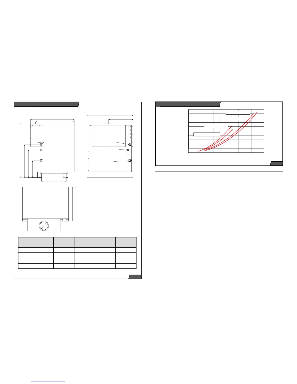
960
850
52
544
92
125
370
605
720
1195
A
B
75
111
Æ G 6/4"
G
1"
Æ G 6/4"
C
Æ D
770
objemový prùtok vody V (m /h)
3
tlaková ztráta p (Pa)
20000
18000
20
0
4681012
16000
14000
12000
10000
8000
6000
4000
2000
65, 85 KLO / KLO EKO
100 KLO / KLO EKO
130 KLO / KLO EKO
150 KLO / KLO EKO
Model 65 KLO /
KLO EKO
85 KLO /
KLO EKO
100 KLO /
KLO EKO
130 KLO /
KLO EKO
150 KLO /
KLO EKO
A 850 1010 1170 1410 1570
B 460,5 540,5 620,5 740, 5 820,5
C 860,3 850,3 840,3 825,3 825,3
D 180 200 220 250 250
brackets for fitting thermostat sensors and
a thermometer, and lugs on feet for connecting the body to the boiler base. The
KLO EKO series boilers use low-emission
burner tubes, the KLO series boilers use
standard tubes. Depending on the output,
the boiler has 7 to 16 burner tubes and a
complete gas route.
The burner plate is fitted with a gas distribution section, the actual burner tubes
and an ignition device. The gas route
consists of a gas supply pipe section terminated with a combined gas valve. The
combined gas valve controls the supply
of gas into the boiler depending on the
required and reached operating states of
the whole system (i.e. the boiler combined
with the heating system); its outlet is already the gas distribution section of the of
the burner plate, terminated with 7 to 15
jets (one for each burner tube).
Igniting the burner and watching that it is
running is done by a Polidoro low-emission ignition burner. When a request is
sent to ignite the main burner, after waiting
time T
w
= 10 seconds, the ignition burner
Accessories
Pressure loss (Pa)
Fig. 1
Basic and Connecting Dimensions
Pressure loss of the boiler´s body
Fig. 2
Flow of water volume V (m3/h)
Page 5

8
9
is automatically ignited. It is ignited by an
ignition spark and its flame is detected by
an ionisation electrode. After the ignition
burner has steadied up and the ionisation
circuit closed, the main gas supply valve
to the main burner opens. If the ignition
burner does not ignite within a safety time
T
s
= 25 seconds, the gas supply to the
main burner and to the ignition burner is
automatically shut off. If the flame during
normal boiler operation goes out, the automatic ignition system will repeat the ignition cycle of the ignition burner. If the loss
of ionisation prevails, the boiler will switch
to a fault status (the light of the “Unlock
automatic fault signalling system” button
on the control panel lights up). After a
waiting time of approximately 10 seconds,
the fault status can be manually cancelled
by pressing the RESET button.
The ignition burner remains on while the
main burner is on.
In the event of power supply failure, the
gas supply to the burner is automatically
shut off. When power supply is restored,
the boiler will automatically restart itself.
KLO
1
2
3
4
5
6
7
8
10
9
11131415
16
18
22
20
21
19
2
3
4
5
6
7
8
10
9
12131415
16
18
19
20
1
21
22
11
17
17
1. Main control panel
2. Chimney thrust detector system cover
3. Fume exhaust
4. Chimney thrust detector
5. Fume thermostat
6. Heating water outlet
7. Gas supply
8. Cast iron body segments
9. Heating water inlet
10. Combustion chamber
11. Secondary air supply
12. Supply burning air
13. Burner
14. Supply burning air
15. Jet
16. Combining pipeline gas
17. Operator burner
18. Gas armatures*
19. Boiler covering
20. Case for sensors
21. Main control panel
22. Automotive ignition
automatics
* For models 130-150 KLO / KLO EKO is used only 1 gas armature.
KLO EKO
KLO
The combustion fumes collector is connected to a chimney thrust detector and
behind it is terminated in a boiler exhaust
outlet (on a fumes flue connection). The
collector is equipped with a removable
cleaning lid, which is accessible after removing the top boiler’s cover.
The chimney thrust detector system
(SKKT) works on the principle of monitoring the combustion fumes temperature
inside the collector. A thermostat situated
inside the collector reacts to an increase
of the combustion fumes temperature
caused by a reduced chimney effect will
shut the boiler down (by shutting off gas
supply to the burner).
The boiler has covers, which are rigidly
fixed to the rear and side-wall, a removable wall and a removable top cover. The
boiler’s control panel is located in the top
section.
The boiler body base is a single steelbase on which the body of the boiler and
the covers are mounted.
Boiler Installation Guidelines
The PROTHERM KLO / KLO EKO boilers can be put into operation only by an
authorised service organisation in accordance with UBP SR Public Notice No. 74/
1996. Installations, putting into operation,
warranty and post-warranty service are
done by a network of manufacturer’s contractual service organisations, which meet
the requirements specified above.
Connecting the boiler to gas supply
The PROTHERM Series KLO - ZP / KLO
EKO – ZP boilers are designed to run on
natural gas with nominal pressure in the
distribution network 1.8 kPa (18 mbar) and
a calorific value usually claimed between
9 and 10 kWh/cum. The internal gas distribution system as well as the gas meter
must be of sufficient size, taking into account also other user’s gas appliances.
The gas supply pipe must have an internal
diameter of at least the same size as the
gas connection pipe on the boiler (which
depends on the boiler size), but preferably
one size bigger.
The PROTHERM Series 65 – 85 KLO - P /
65 - 85 KLO EKO - P boilers are designed
to run on propane gas. Propane gas calorific value is given between 12.8 and 13
kWh/kg. Because supplying boilers from
pressure cylinders is problematic, particularly from the capacity and handling point
Fig. 3
Schematic operation diagram
Page 6

10
11
of view, it is recommended that a reservoir
is installed near the building to be heated,
and refilled by an authorised organisation.
Adequately sized propane supply from
the reservoir to the boiler and to other gas
appliances will then be part of the design
and delivery of the reservoir. When installing a propane gas-fired boiler, an accurate
nominal pressure of 3.0 kPa (30 mbar)
must be secured by installing a reduction
valve (station) before the boiler.
Supply of combustion air
Ventilation must guarantee that sufficient
quantity of combustion air is supplied to
the boiler and that the maximum permissible concentrations of harmful gases
in the boiler’s vicinity are not exceeded
and that an acceptable temperature is
maintained there (all in accordance with
Ministry of Environment Public Notice No.
706/2002).
The stationary cast iron PROTHERM
KLO/KLO EKO boilers draw combustion
air from the space in which they are installed. The combustion air supplied to the
boiler must be free of dust and corrosive
and flammable substances (vapours, solvents, paints, adhesives, etc.). The supply of adequate quantity of combustion
air must meet the requirements of STN
070703 “Gas-fired boiler rooms”. Gas appliances connected to combustion fumes
flue must not be located in places where
negative pressure can be created by ventilation fans.
Combustion fumes exhaust
The boiler is designed for combustion
fumes to be removed into a chimney (via
a chimney connection point) with a stabilised thrust of at least 2 Pa. The boiler is
connected to the chimney by a flue of a
diameter corresponding to the flue diam-
quired by the water composition. Depending on the anticipated amount of sludge
trapped; is recommended to desludge the
boiler approximately a week after it has
been put into operation. Functional defects
caused by mechanical dirt are not covered
by the manufacturer’s overall warranty (refer to Warranty Terms and Conditions).
Important: When filling the boiler with
water, all air in the boiler as well as in
the heating system has to be thoroughly
bled.
Using antifreeze liquid
KLO and KLO EKO boilers may be filled
with an antifreeze liquid, namely product
called ALYCOL TERMO, produced by
Slovnaft Moravia. Using other antifreeze
products will invalidate the manufacturer’s
warranty on parts and related costs.
Properties of the heating system
and filling the system with water
The boiler must be connected to the heating system distribution pipes (G6/4”) and
to the gas supply pipe (G 1”) in such a way
that the connection end pieces are not
stressed by forces imposed by the heating system distribution pipes or by the gas
supply pipe. The connection end pieces
have an external thread.
We recommend equipping the connection
eter of the flue connection point (depends
on the boiler size). The flue is part of the
delivery.
It is forbidden to put inside the flue objects
obstructing the flow of combustion fumes
(e.g. various types of heat exchangers to
increase utilisation of the heat).
Construction of the flue and the chimney
must comply with STN 06 1610, STN 73
420 and STN 73 4201 standards.
By complying with requirements of these
standards, we prevent undesirable phenomena from occurring, such as excessive cooling of the fumes, penetration of
dampness into walls, fluctuations in the
chimney effect (thrust) and thus undesirable effects on the boiler’s functioning.
Requirements on heating water
quality
The PROTHERM KLO / KLO EKO boilers
are designed for heating water of up to
400 kPa (4 bar) gauge pressure, which is
in compliance with STN 07 7401.
The first fill as well as top up water must
be clear and colourless, and be free of
suspended substances; oil and chemically corrosive additives, under no circumstances may be acidic (i.e. have pH factor
greater than 7) and must have minimal
carbonate hardness.
For softening the first fill water can be used
trisodium phosphate or a one-off dose of
chelating agent.
It is recommended to install before the
boiler (i.e. to the return heating water pipe)
a sludge trap. Its design should allow the
device to be emptied in regular intervals
without draining a great deal of heating
water in the process. The sludge trap can
be combined with a filter, but the filter itself
would not provide adequate protection.
Both the filter and the sludge trap must
be checked regularly and cleaned, as re-
pipes with isolation valves, so that when
repairing the boiler it is not necessary to
drain water from the heating system.
The heating system should be designed
in such a way that a permanent circulation
of the heating water is possible at least
through some radiators.
The boiler does not have an expansion
vessel or a safety valve built in, therefore
these devices can be connected only to
an external system, designed in accordance with STN 06 0310 and safety features compliant with STN 06 0830.
The boiler can work in systems with both
an open and closed (pressurised) expansion vessel. However, when using the
boiler in systems with an open expansion
vessel, it is necessary to harmonise the
temperature setting of the emergency
thermostat (98°C) and limit the operation
range on the heating controls. This setting
must be done by authorised service only.
In open expansion vessels, correct water
level must be maintained (between the operating minimum and maximum). Closed
expansion vessels when being filled up
must be set according to the heating system.
For filling and draining purposes, the boiler
is equipped with a filling (draining) valve.
After being filled up, the system must be
thoroughly bled.
After reconstructions, in unsuitable building disposition, etc., the boiler may be
connected to the heating system and to
the gas supply by flexible hoses, but only
those designed for this purpose. When using flexible connections, these should be
as short as possible, protected against
mechanical and chemical stress and damage, and be always replaced before the
end of their life or before their parameters
deteriorate with new ones (as determined
by their manufacturer).
Fig. 4
Page 7

12
13
Before final installation of the boiler, the
heating system distribution pipes must be
flushed several times by pressurised water. In old, already used systems, this is
done in the opposite direction to the heating water flow.
Boiler’s location
If there are special requirement on manipulation with the boiler (e.g. in order to
prevent its covers from getting damaged,
to reduce its width, etc.), the boiler, delivered assembled, can be partially disassembled.
Enough manipulation space should be
left around the boiler and the connected
devices, to allow adequate access and
works using tools to be performed.
Leaving adequate free space around the
boiler will also satisfy the requirements for
the so-called safe (fire) distance.
Prevention against freezing
Unless the boiler is protected against
freezing by implementing technical and
organisational measures around the boiler (controls, operator), it will necessary to
shut it down possibly together with some
other equipment in the boiler’s vicinity (the
boiler room), such as for instance a water
treatment plant, water top-up equipment,
etc., or the entire heating system will have
to be shut down, i.e. the water drained,
and the supply of water, gas and electricity to the boiler shut off.
Connecting the boiler to power
supply
The boiler is designed to be hardwired to
power supply. The electric boiler’s hardwired connection must have a disconnection device built in – a main switch, with
the distance between open contacts at
least 3 mm in all poles, with all regulations
for switching the boiler being abided by.
The boiler is connected to power supply
by means of a terminal box which has
terminals for a three-wire connection. The
boiler must be wired to power supply in
accordance with STN 33 2000-4-46
[Slovak
Technical Standard Specifications]
. Its protective contact
(peg) must be always connected to the PE
or PEN wire (green and yellow).
It is prohibited to use any type of adapters,
extension cables, etc. The boiler is protected against overloading and short circuit by a T 4A / 250 V fuse, located on the
control panel. The fuse must be replaced
by authorised service only.
Boilers controlled by a room thermostat
must use only thermostats which have a
potential-free output, i.e. those which do
not feed any alien voltage into the boiler. It
is recommended that a suitable room thermostat is selected by authorised service.
The boiler must be placed on a building
base, i.e. floor (or on a pedestal). The
floor must have at least normal load-bearing capacity and must not be slippery.
The space around the boiler may be only
cleaned in a dry way (e.g. by vacuuming).
The boiler must be positioned on an inflammable mat. If the floor is constructed
of a flammable material, it must be put on
an inflammable, thermally insulating mat,
exceeding the boiler’s footprint by at least
100 mm.
When transporting the boiler with the covers on, doors must be at least 100 cm
wide.
Important: Unauthorised persons must
not interfere with the boiler’s setting (particularly those with an impact on the combustion process), to prevent an increased
generation of harmful substances in the
combustion fumes, operation noise, reduced heat utilisation or heat generation,
etc.).
Table 1: Flammability classes of building materials and products
Flammability classes
of building materials
and products
Building materials and products classified by flammability
class (selection from STN 73 0823)
A – non-flammable granite, sandstone, bricks, ceramic tiles, mortars, fire pro-
tection plasters
B – very low flammability
aluminium, Izumin, Heraklit (hardboard), Lignos, basalt felt
boards, fibre glass boards
C1 – low flammability beech wood, oak wood, Hobrex boards, plywood, Werzalit,
Umakart, Sirkolit
C2 - stredne horľavé pine wood, spruce wood, spruce boards, chipboards and
cork boards, rubber
C3 – highly flammable
tar paper, wood fibre boards, cellulose materials, polyurethane, polystyrene, polyethylene, PVC
The boiler must not be installed in an environment in which the burner tubes can get
clogged up by dirt or biological agents (small living creatures).
The boiler has an outlet for connecting
a room thermostat, located on a printed
circuit board. As an option, the boiler can
be supplied with the so called switching
kit, used to interconnect with boiler an
equithermal control unit. For a specific
control unit type must be ordered a specific kit. These switching kits support as
standard Siemens Albatros control units
RVA43.222, RVA63.242 and RVA63.280,
Important: If a different control unit is used,
it must not restrict of disable the boiler’s
safety functions.
Siemens control units
Albatros RVA43.222 is an equithermal
control unit designed for standalone boilers or cascaded boilers.
It is suitable for serial connection to the
source of heat with:
• one or two-stage burner
• hot water supply pump or bypass valve
• boiler pump, supply pump, or heating
circuit pump
Heating circuit is controlled equithermally,
hot utility water heating is controlled by
temperature in the tank and a time programme.
By combining more RVA43.222 control
units, you can create a stepped up cascades of multiple (maximum 16) sources
of heat.
Albatros RVA63.242 is an equithermal
control unit designed for serial connection
to the source of heat with:
• one or two-stage burner, 1BMU
• hot water supply pump or hot water heating bypass valve
• three-point blender drive with circulation
pump
• various multi-function outlet applications
Page 8

14
15
123 4 5 6 7
891011121314
Albatros RVA63.242 is an equithermal
control unit designed for serial connection
to the source of heat with:
• one or two-stage burner, 1BMU
• hot water supply pump or hot water heating bypass valve
• one or two heating circuits with a three-
-point blender drive and circulation
pump, or with a circulation pump only
All the above equithermal control units
can be mutually combined, allowing more
complex heating systems to be built. More
detailed documentation is supplied with
the equithermal control units, or can be
viewed on website www.siemens.cz.
Connecting room control unit
The boiler has a special terminal box for
connecting a room control unit, located
underneath the control panel. The zeropotential contact control unit is connected
by an electrical wire. If a unit requiring
230 V power supply is used (bimetal, with
heating resistor), it has to be connected
to the terminal box by a three-core cable.
The boiler’s manufacturer supplies suitable room control units as an option.
Fig. 5
1. Main boiler switch
2. “Flame out” control light
3. “Boiler overheated” control light
4. Thermometer
5. Pressure gauge
6. Equithermal control unit
1)
7. Gas leakage detection device
2)
8. Boiler output control switch
9. Pump thermostat
10. Operation heating control
11. Emergency thermostat
12. Combustion gases thermostat
13. RESET button
14. Power mains fuse (4 A)
Control panel and signallization
Locations of the boiler’s control and signalling elements are illustrated in the picture of the
boiler’s control panel (Fig. X).
The boiler has two control panels:
– Main control panel, with basic control elements for the user
– Service control panel (located under the front cover), used for service settings.
Description of control elements
Main switch – used to cut off power supply
to the boiler.
“Flame out” control light – a red light signalling a fault caused by the flame going
out. The fault may be caused by gas supply interruption during start up or while the
boiler is running.
“Boiler overheated” control light – and orange light signalling a fault triggered by:
– the combustion fumes thermostat af-
ter drop or loss of chimney effect,
– the emergency thermostat when the
heating water temperature exceeds
105°C (98°C in open systems).
Thermometer, pressure gauge – show
temperature and pressure, respectively, of
the heating water in the boiler.
Boiler output switch (two flames – one
flame) – used to switch between two op-
eration stages (LOW/HIGH).
Pump thermostat – used to protect the
cast iron body of the boiler against condensation. After igniting the burner, the
boiler pump runs until the temperature
exceeds 60°C (factory setting). This temperature setting may be changed by authorised service only.
Heating operation controls – used to set
the heating water temperature.
Important: The selected temperature
must be always higher than the temperature set on the pump thermostat. If not, the
pump will stay permanently switched off.
Emergency thermostat – used to protect
the boiler against overheating. If overheated, the thermostat will shut the boiler
down. The boiler can be restarted after
the heating water in the boiler has cooled
off by pressing an unlocking button (11),
which is sometimes located under a plastic plug.
Combustion fumes thermostat – used to
shut the boiler down when the chimney effect has been reduced or lost. The boiler
can be unlocked only after the combustion fumes thermostat has cooled off, by
pressing an unlocking button (12).
Important: The boiler must never be run
with the above described safety elements
(combustion fumes and emergency thermostat) disabled or replaced by devises
other than those specified by the manufacturer! Under no circumstances may the
user manipulate with these elements.
RESET button – by pressing this button,
the fault signalled by the “Flame out” red
control light can be fixed. If the fault is signalled repeatedly, call authorised service.
For fault statuses triggered by the combustion fumes of emergency thermostat,
using the RESET button is ineffective.
In such cases it is necessary to call authorised service, which will diagnose the
problem and after repairing the fault put
the boiler back into operation.
Power mains fuse – protects the boiler’s
electrical wiring against overloading and
short circuit.
Model KLO / KLO EKO Max. power / Low power (kW)
NATURAL GAS
Max. power (kW) PROPAN
65 65 / 49 55 / -
85 85 / 59
100 99 / 70 -
130 130 / 91 -
150 150 / 105 -
Table 2 :
Maximum and Low power of the boiler.
Fig. 5
Control panel
1)
Not a standard boiler accessory
2) Optional accessory, available with 130 - 150 KLO and KLO EKO boilers only
Page 9

16
17
Operator’s duties
In addition to setting the control elements
(including control unit), the operator must:
1) comply with the Local Operating Mode
– LOM (or, if one has not been devised
yet, proceed in accordance with operating instructions for each device and its
components (for the boiler, control unit,
pumps, expansion vessel…) – refer to the
section General Requirements,
2) maintain the area around the clean
and neat,
3) make sure that no works unrelated to
running and maintaining the boiler are
performed in its vicinity,
4) enforce and secure (e.g. by warning
signs or locking the entrance door, etc.)
that no unauthorised persons are present
near the boiler (i.e. persons without necessary knowledge, younger than 18, certified, etc.); the presence of such persons
in the boiler’s vicinity is permissible only
when accompanied by authorised persons,
5) keep passages around the boiler and
entrance door free,
6) keep important operation records (the
so called Operation Diary – OD) as laid
down in LOM.
In addition to the measures taken in practical situations – see section General Requirements – the operator must always
shut the boiler down whenever it becomes
impossible to control the boiler reliably,
even manually. Supplies must always be
shut off in the event of leaks of any media
(in particular gas, but also heating water
and electricity) and an authorised service
called.
The operator must also shut the boiler
down and close all supplies (if necessary
not only in the boiler’s vicinity but also sup-
plies to the building or at least its relevant
part) even if undesirable situations have
not occurred yet, but there is a danger that
they might occur (e.g. when fire breaks in
the building).
Preparing and starting the boiler
Preparing and starting the boiler up is part
of the process of putting the boiler into operation, which must be performed by authorised service.
First live test run
The first live test run is a short live run of
the boiler to make the last check whether
the boiler has been installed correctly and
the heating system functions properly. It
is part of the process of putting the boiler
into operation, which must be performed
by authorised service.
The actual operation
The boiler runs automatically according to
the setting of control elements, the user
performs only the following operations,
which have to demonstrated to the user
by the authorised service technician who
put the boiler into operation:
1. Switching the boiler on or off using the
power mains switch on the boiler’s control
panel.
2. Controlling the boiler’s operation using
selected control unit, which are always
supplied with separate operating instructions.
3. Setting and checking the required heating water temperature within a 0 to 85°C
range on the boiler’s thermostat.
4. Switching between nominal or reduced
output (HIGH/LOW).
5. When a fault is detected, a fault control
light will switch on. In the event of power
Running the Boiler
failure, the burner will be shut down, and
when power supply is restored, the burner
will be automatically re-ignited. The fault
state can be unlocked by pressing the RESET button in the service section of the
control panel. If the fault reoccurs, call authorised service.
6. Unlocking the emergency thermostat. If
the emergency thermostat shuts down the
boiler, the orange light on the boiler’s control panel will light up, signalling, “Boiler
overheated”. The thermostat is unlocked
by pressing button 11, situated in the
service section of the control panel. If the
fault reoccurs, call authorised service.
7. Unlocking combustion fumes thermostat (reverse fumes flow safety cut-out).
When this detector shuts down the boiler,
the orange control light on the main control panel will light up, signalling, “Boiler
overheated”. The cutout device (TS) is
unlocked by pressing button 12, situated
in the service section of the control panel.
Important: If the fault reoccurs, disconnect
the boiler from power supply and call authorised service.
Important guidelines
1. The boiler room must have a permanent
supply of air.
2. The boiler operator must be at least 18
years old.
3. The boiler must be connected to 230
V/50 Hz power supply mains with appropriate circuit breaker.
4. When putting the boiler out of operation
for a longer period of time, disconnect it
from power mains.
5. If a defect occurs in the combustion
fumes exhaust system and is triggered
by the chimney thrust detector (reverse
thrust, blocked chimney), the reverse
fumes flow cutout device will shut off the
supply of fuel into the boiler.
6. The boiler room must be kept clean
and free of dust. All sources of dirt must
be removed from the boiler room and during works, which generate dust (insulation
works, cleaning), the boiler must be shut
down. Even partially blocked burner by
dirt degrades the combustion process and
endangers economic and reliable running
of the boiler. We do not recommend keeping in the boiler room any pets (dogs, cats,
etc.).
7. Before commencing any works, which
generate flammable vapours or gases that
might penetrate the boiler room, or works
with temporary fire or explosion hazard
(gluing on floor covering material, painting
with flammable paints), the boiler must be
shut down beforehand.
8. No objects made of flammable material
may be placed on the boiler or within a
distance less than a safe distance from it.
9. Getting close to or touching the flame
checking-window may cause burns.
10. The user must have the installation,
putting into operation, regular maintenance and repairs done by a PROTHERM
authorised service. Failing to abide by this
condition will result in invalidating the warranty provided by the boiler’s manufacturer. The Certificate of Quality and Completeness of the PROTHERM KLO Boiler,
after being filled in and signed by an authorised service organisation, serves as a
Warranty Certificate.
11. The boilers must once year undergo
regular maintenance as laid down in
Chapter X.
12. The boiler must be run in accordance
with these Operating Instructions and oth-
Page 10

18
19
er applicable regulations. Incorrect use of
the boiler might result in reducing its life,
but also in damages to health and property.
Starting the boiler up
The boiler the functioning of which has already been verified by the first live test is
started up as follows:
– Set the heating water operating tempe-
rature control to approximately 2/3 of its
full range. You will set it to the required
temperature later. The heating water
temperature has an impact on the heating speed of the UHW reservoir.
– . If the boiler works in conjunction with
an indirectly heated UHW reservoir, set
the reservoir temperature to approximately ½ or its full range.
– . Check the water pressure on the boi-
ler’s pressure gauge. When the water is
cold, the pressure must not be lower
than indicated (by the pressure gauge
red hand – set by authorised service during the first live test run).
– If the boiler is controlled by either an
equithermal or room heating control
unit, set it in accordance with the device’s operating instructions.
– Set the power mains switch to the ON
position (I). The boiler will ignite itself
and start heating the water in the UHW
reservoir (if one is installed). When it
has been heated up, the boiler starts
heating the heating system water. If your
boiler is equipped with an RVA 43.222
equithermal control unit, this function is
achieved by selecting the WINTER
mode.
The boiler switches off:
– when heating the UHW, always when
the UHW temperature reaches the value set on the UHW reservoir thermostat,
– when the heating system water tempe-
rature in the boiler reaches the values
set on the operating heating water thermostat,
– when the required temperature set on
the room or equithermal control unit has
been reached.
If the boiler fails to start up and the emergency state control light is not on, it is
an operating shutdown described above.
After the heating water and UHW have
cooled down and the temperature in the
room dropped, the boiler will automatically
start up.
If the boiler does not start up even after a
longer period of time and does not react to
increasing the set values on the operating
controls or other control elements (room
and equithermal control unit), the problem
is in the boiler, and it is necessary to call
authorised service.
If the boiler has not started up and the
emergency state control light is on, proceed in accordance with the instructions
in Description and Functions of Control
Elements.
Boiler shutdown
If you wish to shut the boiler down for a
short while, use the power mains switch. If
you want to shut the boiler for longer, pull
out the power cord plug out of the socket
and shut off gas supply to the boiler. If
there is no danger of the boiler freezing,
leave the water in, otherwise drain the water from the boiler, from the UHW reservoir and from the system.
Provided the heating system configuration
allows it, when dismantling the boiler drain
the water from the boiler only and leave
it in the heating system to prevent it from
corroding.
We recommend that once a year, preferably before the start of a new heating season, you have the boiler inspected by an
authorised service. This inspection is not
part of warranty. Things to be inspected
are specified in the Service Book.
Mostly it is checking the functions and
condition of the burner, checking and adjusting the output, checking for leaks in the
flue joints (and if necessary sealing them)
and then – if necessary – also cleaning
the burner jets (caution – their interior
must not be damaged!) and cleaning the
boiler’s heat exchanger.
Particularly important is to check the functioning of the emergency and combustion
fumes thermostat. This inspection is also
carried out whenever these components
are serviced.
Maintenance performed by the user
a) Clean the boiler covers as needed,
without removing the top cover. Before
you start cleaning the boiler, disconnect if
from power mains and pull the power cord
plug from the socket. If the boiler surface
is wet, wait until it dries before reconnecting it.
b) Once a week check water pressure in
the heating system and if necessary top up
the water. Water in the heating system can
be topped up only after the temperature of
the water in the boiler has dropped below
40°C (measured on the boiler’s thermometer). Failing to abide by this requirement
may result in damaging the boiler’s block.
c) Check the combustion fumes ducting
for leaks.
d) When discovering any gas leak, shut
the boiler down, shut the gas valve off and
call authorised service.
e) Check and clean the filter and the
sludge trap:
– straight after the first live test run,
– after the first week of operation,
– regularly once a week or at least
once a quarter, depending on the degree of clogging.
Maintenance
Compliance with the requirements on boilers
Compliance of the boiler’s properties are
guaranteed and checked during the manufacturing process by a Quality Control
System which, as confirmed by Certificate
BVQI No. 69097 dated 17 May 2000, meet
the BSN EN ISO 9001:1994 quality standard.
Services of a sustained standard for installations and putting the boilers into
operation, warranty and post-warranty
service, are provided through authorised
contracted service organisations of necessary technical qualification and knowhow (see point X).
The boiler must be used exclusively in
accordance with these Operating Instructions and the accompanying documentation. Whenever you have any doubts or
insufficient information, or if you feel you
didn’t fully understand the instructions, or
if you suspect any unauthorised interference with the configuration and functioning of the boiler, always contact authorised service.
Page 11

20
21
The PROTHERM KLO/KLO EKO gas-fired
boilers are covered by a warranty specified in the Warranty Certificate, Service
Book and the conditions defined in these
Operating Instructions.
Warranty and Warranty Terms and Conditions
Completeness of the Delivery
Delivery of the actual boiler
The PROTHERM KLO/KLO EKO boilers
are delivered completely assembled and
with their functions tested.
Part of the delivery is the following documentation:
– Operating Instructions,
– Product Quality and Completeness
Certificate,
– Warranty Cer tificate,
– Service Book,
– Directory of Service Centres.
Customised delivery
The following optional accessories can be
supplied with the boiler:
– room control unit,
– RVA 43.222 equithermal control unit,
– gas leak detection system,
– UHW heating reservoir,
– three-way distribution valve.
Transportation and Storage
The manufacturer suppliers the boiler
standing on a palette, to which it is secured against moving (by screws). When
manipulating and storing the boiler, do not
apply force on the boiler’s covers! Boilers
without a palette are manipulated on the
boiler’s body base (see Chapter X).
Boilers must be stored in a room, which
meets at least the basic environmental
conditions (non-corrosive, maximum humidity 75%, temperature between 5°C
and 55°C, low dust, no biological agents).
Technical specifications of KLO Series boilers
Boiler type . . . . . . . . . . . . . . . . . . 65 KLO . . . . . . . 85 KLO . . . . 100 KLO . . . . .130 KLO . . . . . 150 KLO
Number of elements . . . . . . . . . . . . . 8 . . . . . . . . . . . 10 . . . . . . . . . . 12 . . . . . . . . . .15 . . . . . . . . . . .17
Version . . . . . . . . . . . . . . . . . . . . . . . . . . . . . . . . . . . . . . . . . . . . . . B11BS
Appliance category . . . . . . . . . . . . II2H3P I2H . . . . . . . . . I2H . . . . . . . . I2H . . . . . . . . . . I2H
Ignition . . . . . . . . . . . . . . . . . . . . . . . . . . . . . . . . . . . . . . . . . . by electric spark
Fuel/ inlet gauge pressure . . . . . . . . . . . . . . . . . . natural gas / 2 kPa, propane / 3.7 kPa
Output stage I / II - ZP (kW) . . . . .49 / 65 . . . . . . . 59 / 85 70 / 99 91 / 130 105 / 150
Output stage I / II - P(kW) . . . . . . . - / 55 . . . . . . . . . . - . . . . . . . . . . - . . . . . . . . . . - . . . . . . . . . . . . -
Input stage I / II - ZP (kW) . . . . 53,5 / 70,6 . . . . 64,7 / 92,4 . . .76,8 / 107,6 . . 98,4 / 141,3 . . . 115,3 / 163
Input stage I / II – P (kW) . . . . . . . - / 60,1 . . . . . . . . . - . . . . . . . . . . - . . . . . . . . . . - . . . . . . . . . . . . -
Efficiency ZP / P (%) . . . . . . . . . . . . . . . . . . . . . . . . . . . . . . . . . . . . 91 / 91
Consumption
Natural gas (cu.m / h) . . . . . . . . . 5,7 / 9,5 . . . . . . 6,8 / 9,8 . . . . . 8,1 / 11,3 . . . 10,4 / 14,9 . . . . 12,2 / 17,2
Propane (kg/h) . . . . . . . . . . . . . . . . 6,1 . . . . . . . . . . . - . . . . . . . . . . . - . . . . . . . . . . - . . . . . . . . . . . . -
Burner jet diameter (mm)
Natural gas / Propane . . . . . . . . . . . . . . . . . . . . . . . . . . . . . . . . . . 2,7 / 1,55
Number of burner tubes (pieces) . . . 7 . . . . . . . . . . . . 9 . . . . . . . . . 11 . . . . . . . . . 14 . . . . . . . . . . . 16
Volume of water in the heating body (l)
. . . . . . . . . . . . . . . . . . . . . . . . . . . .27,7 . . . . . . . . . 34,3 . . . . . . . . 40,9 . . . . . . . . 50,8 . . . . . . . . . 57,4
Max. operating temperature (°C) . . . . . . . . . . . . . . . . . . 85 (80°C for open systems)
Max. operating gauge pressure VV (bar) . . . . . . . . . . . . . . . . . . . . . . 4
Min. operating gauge pressure (bar) . . . . . . . . . . . . . . . . . . . . . . . . . 0,3
Test water gauge pressure (bar) . . . . . . . . . . . . . . . . . . . . . . . . . . . . .8
Power supply . . . . . . . . . . . . . . . . . . . . . . . . . . . . . . . 1/N/PE AC 230 V, 50 Hz/TN-S
Electric input (W) . . . . . . . . . . . . . . . . . . . . . . . . . . . . . . . . . . . . . . .100
Electric protection . . . . . . . . . . . . . . . . . . . . . . . . . . . . . . . . . . . . . IP 41
Noise level (dB) . . . . . . . . . . . . . . . . . . . . . . . . . . . . . . . . . . . . . . . do 55
Removal of combustion gases
Method . . . . . . . . . . . . . . . . . . . . . . . . . . . . . . . . . . . . . . . . . .through chimney
Flue diameter (mm) . . . . . . . . . . . . 180 . . . . . . . . . . 200 . . . . . . . . .220 . . . . . . . . . 220 . . . . . . . . . . 250
Minimum chimney thrust (mbar) . . . . . . . . . . . . . . . . . . . . . . . .0,025 / 2,5 Pa
TTemperature of combustion fumes at max. output ZP / P(°C) . 129 / 115
NOX class . . . . . . . . . . . . . . . . . . . . . . . . . . . . . . . . . . . . . . . . . . . Class III
Combustion fumes flow in weight terms at min./max. output
Natural gas (g/s) . . . . . . . . . . . . . 44 / 46,3 . . . . . .53 / 60,5 . . . . .63 / 70,5 . . . . . 81 / 92,6 . . . . . . 95 / 107
Propane (g/s) . . . . . . . . . . . . . . . . - / 45,7 . . . . . . . . . - . . . . . . . . . . . - . . . . . . . . . . . .- . . . . . . . . . . . . -
Connection dimensions
Gas / heating water connection . . . . . G1" / G6/4"
Boiler width (mm) . . . . . . . . . . . . . . 850 . . . . . . . . . 1010 . . . . . . . 1170 . . . . . . . .1410 . . . . . . . . . 1570
Boiler height / depth (mm) . . . . . . . . . . . . . . . . . . . . . . . . . . . . . 1195 / 960
Boiler weight (kg) . . . . . . . . . . . . . . 258 . . . . . . . . . .332 . . . . . . . . 395 . . . . . . . . . 482 . . . . . . . . . 546
Page 12

22
23
Assembling the boiler after delivery
The boilers Series KLO / KLO EKO are
for transportation reasons delivered with
the thrust breaker installed in a horizontal
position. After the boiler has been delivered to the point of installation, the thrust
breaker must be installed in the operating
position. The installation procedure is as
follows:
1. Remove the top boiler cover which is
fastened with two self-cutting screws.
2. After having removed the top cover, dismantle the thrust breaker. The thrust
breaker is attached with three self-cutting screws to the internal boiler bulkhead (Fig. 6).
3. Pull out part of the thrust breaker and
rotate it so that the combustion fumes
neck is pointing vertically upwards. Insert this part into the counter-part and
secure it with ten self-cutting screws.
The line in Fig. 7 indicates the joining of
the two thrust breaker parts.
4. After assembling the thrust breaker, you
must install a sensor (capillary) of the
combustion fumes thermostat, which is
located inside the boiler, next to the
thrust breaker. Insert the sensor in the
hole at the back of the thrust breaker
and fasten it with the clip and the self-
-cutting screw provided for this purpose
(Fig. 8).
Boiler covers
The front cover is removable. It is held
by spring clips which are attached in the
top corners. When removing the cover,
the pressure of the spring clips gripping
the holding pins must be overcome. After
dropping it down first, the cover can be
completely removed.
Technical specifications of KLO EKO Series boilers
Boiler type . . . . . . . . . . . . . . . . 65 KLO EKO . . .85 KLO EKO 100 KLO EKO 130 KLO EKO 150 KLO EKO
Number of elements . . . . . . . . . . . . . 8 . . . . . . . . . . . 10 . . . . . . . . . . 12 . . . . . . . . . .15 . . . . . . . . . . .17
Version . . . . . . . . . . . . . . . . . . . . . . . . . . . . . . . . . . . . . . . . . . . . . . B11BS
Appliance category . . . . . . . . . . . . II2H3P I2H . . . . . . . . . I2H . . . . . . . . I2H . . . . . . . . . . I2H
Ignition . . . . . . . . . . . . . . . . . . . . . . . . . . . . . . . . . . . . . . . . . . by electric spark
Fuel/ inlet gauge pressure . . . . . . . . . . . . . . . . . . natural gas / 2 kPa, propane / 3.7 kPa
Output stage I / II - ZP (kW) . . . . .49 / 65 . . . . . . . 59 / 85 70 / 99 91 / 130 105 / 150
Output stage I / II - P(kW) . . . . . . . - / 55 . . . . . . . . . . - . . . . . . . . . . - . . . . . . . . . . - . . . . . . . . . . . . -
Input stage I / II - ZP (kW) . . . . 53,5 / 70,6 . . . . . 64 / 92,4 . . .75,5 / 107,6 . . .98,4 / 141 . . . . 113,5 / 163
Input stage I / II – P (kW) . . . . . . . - / 59,8 . . . . . . . . . - . . . . . . . . . . - . . . . . . . . . . - . . . . . . . . . . . . -
Efficiency ZP / P (%) . . . . . . . . . . . . . . . . . . . . . . . . . . . . . . . . . . . . 92 / 92
Consumption
Natural gas (cu.m / h) . . . . . . . . . 5,6 / 7,5 . . . . . . 6,8 / 9,8 . . . . . 8,1 / 11,3 . . . . 10,4 / 15 . . . . 12,2 / 17,2
Propane (kg/h) . . . . . . . . . . . . . . . . 6,1 . . . . . . . . . . . - . . . . . . . . . . . - . . . . . . . . . . - . . . . . . . . . . . . -
Burner jet diameter (mm)
Natural gas / Propane . . . . . . . . . . . . . . . . . . . . . . . . . . . . . . . . . . 2,6 / 1,6
Number of burner tubes (pieces) . . . 7 . . . . . . . . . . . . 9 . . . . . . . . . 11 . . . . . . . . . 14 . . . . . . . . . . . 16
Volume of water in the heating body (l)
. . . . . . . . . . . . . . . . . . . . . . . . . . . .27,7 . . . . . . . . . 34,3 . . . . . . . . 40,9 . . . . . . . . 50,8 . . . . . . . . . 57,4
Max. operating temperature (°C) . . . . . . . . . . . . . . . . . . 85 (80°C for open systems)
Max. operating gauge pressure VV (bar) . . . . . . . . . . . . . . . . . . . . . . 4
Min. operating gauge pressure (bar) . . . . . . . . . . . . . . . . . . . . . . . . . 0,3
Test water gauge pressure (bar) . . . . . . . . . . . . . . . . . . . . . . . . . . . . .8
Power supply . . . . . . . . . . . . . . . . . . . . . . . . . . . . . . . 1/N/PE AC 230 V, 50 Hz/TN-S
Electric input (W) . . . . . . . . . . . . . . . . . . . . . . . . . . . . . . . . . . . . . . .100
Electric protection . . . . . . . . . . . . . . . . . . . . . . . . . . . . . . . . . . . . . IP 41
Noise level (dB) . . . . . . . . . . . . . . . . . . . . . . . . . . . . . . . . . . . . . . . do 55
Removal of combustion gases
Method . . . . . . . . . . . . . . . . . . . . . . . . . . . . . . . . . . . . . . . . . .through chimney
Flue diameter (mm) . . . . . . . . . . . . 180 . . . . . . . . . . 200 . . . . . . . . .220 . . . . . . . . . 250 . . . . . . . . . . 250
Minimum chimney thrust (mbar) . . . . . . . . . . . . . . . . . . . . . . . .0,025 / 2,5 Pa
TTemperature of combustion fumes at max. output ZP / P(°C) . 125 / 100
NO
X
class . . . . . . . . . . . . . . . . . . . . . . . . . . . . . . . . . . . . . . . . . . . Class V
Combustion fumes flow in weight terms at min./max. output
Natural gas (g/s) . . . . . . . . . . . . . 44 / 46,3 . . . . . .53 / 60,5 . . . . .63 / 70,5 . . . . . 81 / 92,6 . . . . . . 95 / 107
Propane (g/s) . . . . . . . . . . . . . . . . - / 45,7 . . . . . . . . . - . . . . . . . . . . . - . . . . . . . . . . . .- . . . . . . . . . . . . -
Connection dimensions
Gas / heating water connection . . . . . . . . . . . . . . . . . . . . . . . . . G1" / G6/4"
Boiler width (mm) . . . . . . . . . . . . . . 850 . . . . . . . . . 1010 . . . . . . . 1170 . . . . . . . .1410 . . . . . . . . . 1570
Boiler height / depth (mm) . . . . . . . . . . . . . . . . . . . . . . . . . . . . . 1195 / 960
Boiler weight (kg) . . . . . . . . . . . . . . 317 . . . . . . . . . .369 . . . . . . . . 421 . . . . . . . . . 499 . . . . . . . . . 550
These instructions are intended for specialised service only, and together
with Operating Instructions and Service Book provide technical guidelines
for installing, setting up and maintaining the boiler.
Installing the Boiler
a
b
c
Fig. 6
Fig. 7
Fig. 8
Page 13

24
25
The top cover can be removed after the
two self-cutting screws located at the back
of the boiler have been removed. When
the screws have been removed, lift the
cover upwards.
The boiler’s control panel front can be
dismantled after removing the two selfcutting screws in the panel’s top corners.
The remaining covers (side and rear) are
attached by three lugs and self-cutting
screws to the boiler’s chassis. The covers
are connected by protective wires to the
boiler’s electrical wiring.
Heating system pump
Select the heating system pump according to the design. Problems (e.g. insufficient heating water circulation) caused by
using a different than prescribed pump are
not covered by the manufacturer’s warranty. In addition to other aspects, the pump
delivery pressure rating must be designed
taking into account overall losses in the
heating system and in the boiler.
Properties of the heating system
and filling it with water
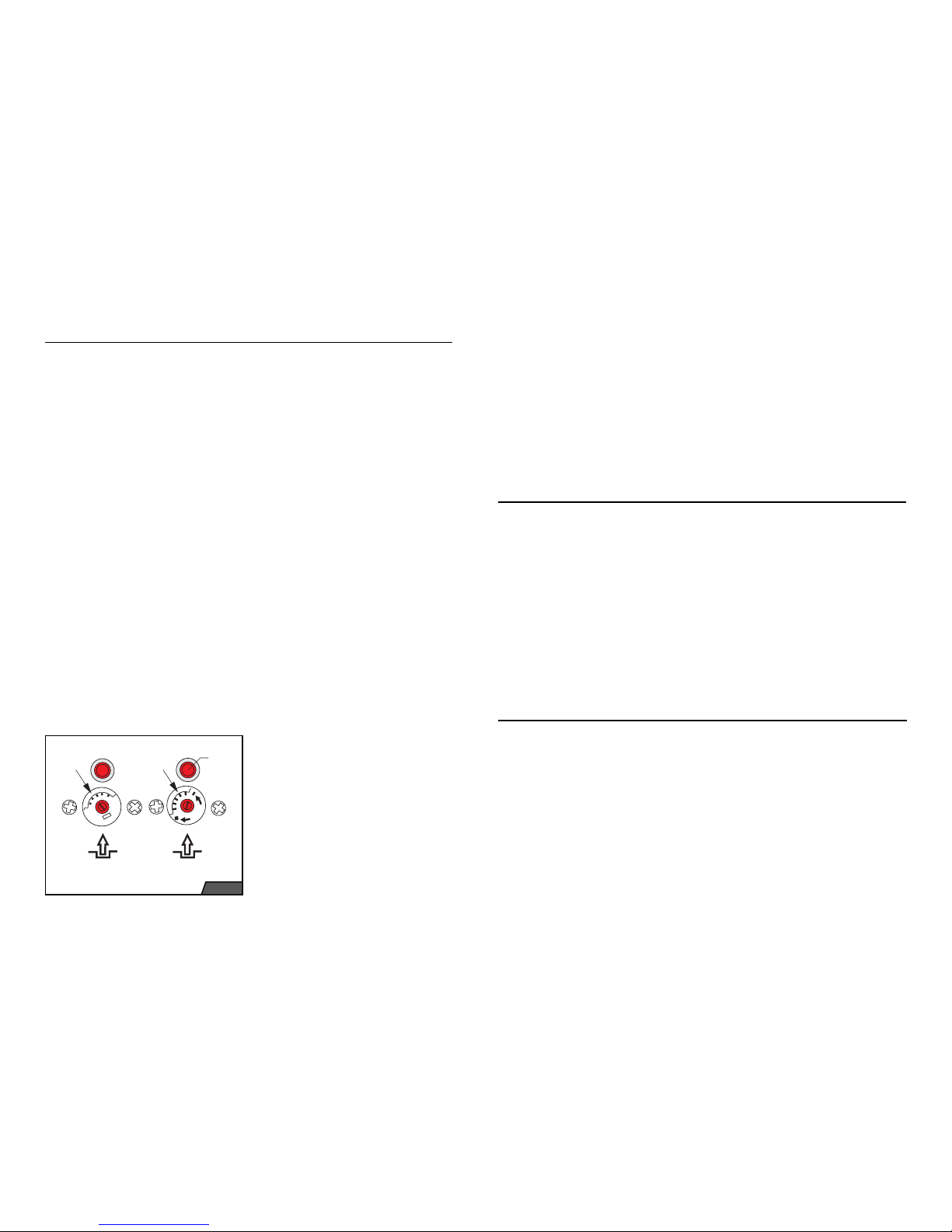
The emergency thermostat temperature
must be set depending on the expansion
vessel type (closed or open). The emergency thermostat is located under the
boiler’s front cover (see Fig. X). For open
systems, set the emergency temperature
to 98°C, for closed systems to 105°C.
In open systems it is also necessary to
limit the range of the operating heating
water control unit to not more than 85°C,
to prevent overlapping of their ranges due
to tolerances, and undesirable reactions
of the emergency thermostat.
The operating control unit limiting is done
with an arresting wire clip situated inside
the control button. The clip can be accesses after pulling the button off the thermostat shaft. The setting must be checked in
an operation test.
After filling the heating system with water,
bleeding it and adjusting the expansion
pressure vessel (if one is installed), mark
the resultant pressure of the heating water
in cold state by pointing the red (adjustable) hand of the boiler’s pressure gauge
at it.
Instructions for installing closed
expansion pressure vessels
Expansion vessels and safety pipes (connecting the boiler with the pressure vessel)
must be protected against freezing. The
maximum operating pressure in closed
expansion vessels must mot be lower than
the opening pressure of the safety valve,
and this must not be higher than the permissible operating pressure of the boiler’s
body; hence it is not recommended that
the operating pressure of the expansion
vessel exceed the operating pressure of
the boiler’s body. Closed heating systems
(with a closed expansion vessel) must be
equipped with a low water level detector; if
the water drops below the minimum level,
the boiler must be shut down in such a
way that it can be restarted only after operator intervention.
The heating water system pipes, its joints
and embedded elements (shutting valves,
meter connectors and meters, etc.) must
not be causes of leaks, i.e. they must be
able to withstand the maximum operating
pressure and temperature with a sufficient
reserve.
The boiler’s electrical compartment as
well as the service section of the control
panel is accessible after folding the top
boiler cover. After dropping the cover forward, the terminal box becomes accessible for connecting accessories. The panel
remains connected with the electrical
compartment by wires and capillaries of
meters and thermostats.
Important: the boiler must be earthed.
If the boiler is run with a room control unit,
before it can be connected, the jumper in
the terminal box must be removed. Otherwise the jumper is left in.
The room control unit’s power supply wires
are connected to terminals Pr1 and Pr2,
positions 4 and 5. Recommended wire
cross-section is 0.5 to 1.5 sq. mm.
The principle of the room control unit outlet’s zero-potential must be respected.
If a bimetal control unit, which requires
230 V power supply is used, then the
phase (L) and neutral (N) unit’s terminals
are connected to terminals Pr1 (position
4) and N of the boiler side, respectively.
The control unit’s outlet terminal is connected to terminal Pr2 (position 5) on the
boiler side. Minimum rating of the control
unit outlet terminals should be 230 VAC/2
A (induction load).
Pump wiring – if the pump’s input exceeds
the boiler’s power supply circuit breaker
rating, an additional switching element
(contactor) must be installed.
Interconnecting the boiler with an
indirectly heated reservoir
The boiler’s internal wiring allows several
ways how to interconnect the boiler with
an indirectly heated reservoir.
a) Topping-up pump.
b) A three-way, actuator-controlled valve
and the boiler thermostat using an RVA
43.222 equithermal regulator.
Connecting equithermal control unit
The boiler’s standard wiring allows the
boiler control to be extended. The so called
switching kit can be ordered, by means of
which the boilers can be connected to one
of Siemens Albatross equithermal control
units, RVA 43.222, 63.242 or 63.280. Basic properties or these equithermal control
units are detailed on page 13.
For connecting an equithermal control
unit, the printed circuit board (behind the
control panel) is equipped with a connector, “J1”, which is as standard fitted with
jumpers. The installation is performed as
follows:
1. Take out of the switching kit box the
connector which is already fitted with
wires. Connect lose ends of the wires to
relevant terminal boxes which are also
part of the switching kit, depending on
the control unit type.
Schematic wiring diagrams are shown on
pages 37 - 39.
2. Part of the RVA 63.242 and RVA 63.280
switching kit is an auxiliary printed circuit board which can be used for instance for connecting pumps and valves for
blending circuits. If you are using one of
these, connect the “J1” wire as indicated in the wiring diagram.
Important: each of these control units
requires specific wiring, and hence it is
not possible to use the ready made wiring
for a different type of equithermal control
unit.
3. Disconnect the boiler from power supply.
4. Pull the jumper off the boiler printed circuit board connector and replace it with
the connector supplied with the swit-
Electrical wiring
Page 14

26
27
ching kit of the equithermal control unit.
Check the connector and make sure
that it has not interconnected for instance also an additional opposite pin.
5. Insert the remaining terminal boxes into
the equithermal control unit as shown in
the relevant schematic diagram (pages
37 – 39).
6. Insert the equithermal control unit into
the cut-out in the boiler’s control panel
and secure it against falling out with the
lugs provided. The fixing lugs are located in the equithermal control unit’s corners.
7. If you have used the auxiliary printed
circuit board for the RVA 63.242 and
63.280 control units, connect the auxiliary device leads to corresponding terminals (see the wiring diagram on pages 37 - 39).
8. Depending on the application, connect
temperature sensors to the control unit.
9. Remove from the boiler sump (Fig. 9)
the pump thermostat capillary and replace it with the heating water temperature sensor from the equithermal control
unit.
– The boiler may be restarted only after
the sensor of the reverse fumes flow safety device has cooled off, i.e. after 10
minutes.
The heating water pump thermostat is factory-set to 60°C (recommended temperature) and secured against changes by a
wire clip.
The power mains switch serves as a protection of the boiler’s internal wiring against
overloading and short-circuiting. The boiler’s power mains fuse labelled T1.6A can
be replaced after unscrewing the fuse box
cover, located on the left-hand side of the
service panel.
Important: The fuse may not be repaired
or substituted by a different object.
“Flame out” control light – lighting up of
the red control light signals a fault caused
by unwanted outage of the flame. It can be
unlocked by pressing the RESET button.
If the light comes on repeatedly, the fault
might be caused, besides other, by the following problems:
1. gas mains supply failure,
2. blocked or damaged house gas pres-
sure regulator,
3. insufficient supply of combustion air,
4. insufficient gas jet pressure,
5. defective gas valve,
6. defective automatic ignition system,
7. broken ignition or ionisation cable,
8. defective pre-ignition burner,
9. defective ionisation electrode,
10. clogged up burner tubes.
“Boiler overheated” – lighting up of the
orange control light, signalling one of the
following faults:
1. shutdown by the fumes thermostat after loss or drop of the chimney thrust,
the fault might be caused, among other,
by the following problems:
a) ncorrect temperature setting of the fu-
mes thermostat,
b) obstacle in the chimney route,
c) chimney thrust dropping below 2 Pa,
d) faulty fumes thermostat.
2. shutdown by the emergency thermostat due to overheating which might be
caused, among other, by the following
problems:
a) shut heating water outlet and boiler
outlet valves,
b) incorrect temperature setting of the
emergency thermostat,
c) heating water pump of incorrect rating,
d) clogged up heating water filter,
e) clogged up desludging device,
f) obstacle in the heating system,
g) clogged up fumes/water heat exchan-
ger.
Description of Safety Elements
Important: The pump thermostat will
remain unused. The heating system protection function must be provided by the
equithermal control unit. With the equithermal control unit set to an appropriate mode, set the heating water system
protection temperature to 60°C.
10. Connect the boiler to power supply.
11. Set the equithermal control unit as de-
tailed in this Instruction Guide, in the
enclosed equithermal control unit documentation and in the design documen-
tation for the given application
With an approval by an authorised measurements and control technician, it is possible to use the switching kit also for other
types of control units.
Important: When using any control unit,
the boiler’s operating and safety functions
must not be disabled or by-passed.
The emergency thermostat sensor, the
operating controls sensor and the heating
water temperature pump sensor are located in an indent in the boiler’s body next
to the heating water outlet. The combustion fumes thermostat sensor is located
in the chimney thrust detector device. The
emergency thermostat, the combustion
fumes thermostat and the heating water
pump thermostat are located in the service section of the control panel (see Fig.
X). The emergency and fumes thermostat
are provided with an unlocking button and
a temperature setting scale (see Fig. X).
Unlocking can be done after unscrewing the cover by pressing the unlocking
button. The emergency thermostat can
be unlocked only after the heating water
temperature has dropped. The same applies to the combustion fumes thermostat,
which can be unlocked only after its sensor has cooled off.
Important:
– After reactions of safety devices (emer-
gency and combustion fumes thermo-
stat), the boiler may be put back into
operation only after the cause, which
lead to the shutdown has been identi-
fied.
– The boiler must never be run with the
emergency devices disabled or repla-
ced by other devices that the ones spe-
cified by the manufacturer. After every
servicing of these devices, their correct
functioning has to be checked.
Fig. 10
Fig. 9
Page 15
28
29
Preparing and starting up the boiler
Before actually starting up the boiler, the
following basic tasks have to be carried
out:
a) Fill up the heating system with water.
Check the water pressure on the boiler’s
pressure gauge.
b) Check the boiler’s connection to the fu-
mes exhaust system,
c) Open the gas isolation valve and let
gas into the boiler. Measure the supply
pressure. Bleed the gas connection
pipe.
d) Set the thermostats:
– emergency thermostat (open systems
to 97°C – factory setting, closed sys-
tems with expansion vessel may have
the temperature set to 105°C),
– fumes thermostat to 70°C (can be set
within the range 70-110°C. Setting
change must be approved by the manu-
facturer),
– operating heating water and UHW ther-
mostat (when auxiliary reservoir is used)
is set to approximately ¾ of their respe-
ctive full ranges. The operating heating
water thermostat can be set within the
range 0-85°C.
e) Press the power mains switch. When
using an RVA 43.222 control unit, set
the mode to WINTER. The boiler ignites
and starts heating the UHW. After reaching the set temperature, it starts heating the heating system water. With the
boiler running, check the entire gas route joints for leaks, e.g. using a foam-forming solution. Any leaks (caused by the
boiler’s transportation) must be repaired
and the inspection repeated.
f) At the end before starting the boiler up,
check and if necessary adjust the gas
supply pressure at the outlet from the
gas shutting-valve.
The adjustment is done using the regulation elements on the gas shutting-valve.
Putting the boiler into operation
1. Open the gas supply valve and the
heating system water supply valve.
Set the I/II switch to the II position – manual operation. Set the boiler thermostat to
the maximum temperature.
2. Turn on the main switch on the boiler’s
control panel. Connection to power supply
is indicated by the green light.
3. If everything is OK, the ignition burner
is ignited. The burner’s ignition electrode
sparks for 25 seconds by default. The ignition burner starts up the boiler in reduced
output. If the burner does not ignite within
the ignition cycle, a control light on the power mains modules will light up, signalling a
fault (see Fig. 29). If repeated attempts to
ignite the burner fail, the main switch must
be turned off and the fault diagnosed and
repaired (refer to Chapter 11), and then
the whole process repeated.
4. The boiler’s thermal output can be set
and adjusted as described in Chapter
7.3.
5. Perform a heating test:
– set the I/II switch to the I position,
– on the Albatros control unit enable func-
tion “Chimneysweep”,
– carry out the heating test.
Operation
110
8
0
50 °C100 °C
emergency
thermostat
combustion gases
thermostat
deblockationing
button
First live heating test
The first live heating test is performed by
running the boiler for a short while after its
final connection to the heating system.
Set the boiler’s controls (operating controls, room control unit) so that you reach
as high heating water temperature as possible with as few boiler shutdowns (switch
offs) as possible. Keep the entire system
(the boiler as well as the heating system)
in these conditions until it stabilises itself
(i.e. until the temperature even in the point
furthest away from the boiler stabilises),
and then let it run for at least an hour.
Shut the boiler down. Write down the boiler pressure. Once more carefully bleed
the system and then pressurise it to the
value you have written down.
Let the boiler cool off. Monitor whether
with the dropping temperature the pressure does not drop down significantly. If
the pressure does drop, look for leaks, repair them and repeat the live heating test.
Specialist Maintenance
Part of maintenance (servicing) are also
repairs. These are one-off specialised
works performed immediately whenever
a reason for them occurs (defect, error).
Errors are repaired by replacement, using
correct, exclusively manufacturer’s original or by the manufacturer recommended
parts and components.
Whenever a defect occurs, it is forbidden
to continue running the boiler on a permanent basis for the purpose for which it is
designed!!!
When maintaining and repairing the boiler
(or its parts), measures must be taken to
prevent injuries, particularly by electricity,
by fall (movement) of objects and by burning.
If mechanical maintenance is performed
by people without electrician qualification,
it is absolutely essential before works on
the equipment are commenced to disconnect it from all power supplies, and this not
only with a switch (main, power mains),
but also by disconnecting the supplies
(e.g. with circuit breakers, etc.)!!!
Apart from Operating Instructions, the
tasks performed as part of specialist preventative maintenance are detailed in the
Boiler Service Book.
Converting to Different Fuel Type
Converting to a different type of fuel (natural gas, propane gas) is possible only in
models 65 and 85 KLO / KLO EKO. The
conversion to a different fuel can be done
by the following procedure.
Important: This conversion must be done
exclusively by an authorised service.
The procedure converting to a different
type of fuel:
1. Shut the power supply before the boiler.
2. Disconnect the boiler from power supply.
3. Fold the boiler’s front panel.
4. Remove the jets from the burner console and replace them with jets of appropriate diameter depending on the boiler
type and kind of fuel (refer to the table
provided).
5. Replace the pre-ignition burner jet. Use
jets for the given type of fuel (see Table
X).
6. Honeywell gas valves have in the bottom right corner a black plug. Underneath
the plug is an adjusting valve for the start
up gas supply. Insert into the indented ar-
Fig. 11
Page 16

30
31
row in the adjusting valve a flat screwdriver and turn it by 180°. When running the
boiler on propane gas, the arrow must be
pointing in the direction of gas flow. When
running the boiler on natural gas, the arrow must be pointing in the opposite direction to gas flow.
7. When converting the boiler from natural gas to propane gas, disconnect the
modulator connector.
8. Connect the boiler to power supply
9. Open the gas supply valve before the
boiler.
10. Set the boiler output as described on
page X.
11. Check all gas route joints for leaks
and implement the following safety measures:
– stick a label in a suitable way right on
the boiler, showing on what type of fuel
the boiler now runs,
– record the change, and the name of the
person who made it in the boiler’s accompanying technical documentation.
When converting the boiler, use only original manufacturer-supplied or authorised
parts. When converting to a different type
of fuel, the requirements on the design of
threaded joints for the gas pipes inside the
boiler must be respected, i.e. they must be
sealed only with suitable material for the
installation, and resistant against the used
type of fuel. Safeguard the settings of all
elements for instance by applying a drop
of paint.
65 - 100 KLO / KLO EKO Standard –
Natural Gas (65 KLO/KLO EKO
propane)
1. Remove the gas inlet pressure measuring point screw on the gas valve and attach a pressure gauge (U-tube) to it. The
natural gas supply pressure should not be
lower than 2 kPa.
2. To reduce the supply pressure, tighten
the measuring point screw.
3. Attach a pressure gauge (U-tube) to
the outlet gas measuring point on the gas
valve.
4. Start up the boiler.
5. Let the operating pressure on the burner stabilise for a while before starting the
adjustment.
6. Fold the HIGH/LOW modulator plastic
cover.
7. Check the appropriate high and low output against the table provided.
8. Using the HIGH/LOW switch set the
boiler to nominal output (two flames).
9. Insert an 8 mm spanner on the gas valve
modulator nut and by turning it clockwise
or anticlockwise adjust the boiler’s nominal output.
10. Check the pressure gauge (U-tube)
reading.
11. Set the HIGH/LOW switch to the position LOW (one flame).
12. Adjust the output using the screw on
the modulator, using a 3.5 mm wide flat
screwdriver.
13. Check the output setting
14. Make sure that all measuring points
are properly secured and no gas leaks
from them.
130 – 150 KLO / KLO EKO Standard
– Natural Gas
These models are equipped with a pair
of Honeywell or SIT electromagnetic gas
valves.
1. Remove the gas inlet pressure measuring point screw on the gas valve.
2. Using a pressure gauge (U-tube),
measure the gas pressure supplied to the
boiler. The value should not be lower than
2 kPa.
3. Replace the measuring point screw.
4. Remove the gas outlet to the burner
pressure measuring point and attach a
pressure gauge (U-tube) to it. The meas-
Table 3: Gas valves used by the model
Model Type of gas valve Producer / number of valves
65 KLO / KLO EKO - PROPAN sigma 843, sigma 840 Sit / 2
65 - 100 KLO / KLO EKO - ZP sigma 843, sigma 840 Sit / 2
130 - 150 KLO / KLO EKO - ZP VR 400 B+B high - low Honeywell / 1
130 - 150 KLO / KLO EKO - ZP +
proof of gas-tightness
VR 400 B+B high - low + valve VE
408 AA 1007 for operator burner
Honeywell / 1 + 1 (operator burner)
For all models is used the automatic ignition system 4560 B 1055 (TS 50 sec.)
Gas pressure settings
a
b
c
d
1
3
2
Fig. 12
Fig. 13
Fig. 14
Sigma 840
Sigma 843
Page 17

32
33
uring point is situated on the burner plate
console.
5. Start up the boiler.
6. Let the operating pressure on the burner stabilise for a while before starting the
adjustment.
7. Take orientation reading of the gas
pressure (the values must correspond to
the values specified in Table X).
8. Remove the aluminium plug on gas
valve 1 and lightly turn the plastic output
adjusting screw found inside.
9. Fold the protective plastic HIGH/LOW
modulator cover on gas valve 2.
10. Using the HIGH/LOW switch, set the
boiler to nominal output (two flames).
11. Insert an 8 mm spanner on the gas
valve modulator 2 nut and by turning it
clockwise or anticlockwise adjust the boiler’s nominal output. Adjust the low output
by turning the modulator screw clockwise
or anticlockwise using a 3.5 mm wide flat
screwdriver.
12. Check the output setting.
13. Make sure that all measuring points
are properly secured and no gas leaks
from them.
k
Table 4: Pressure of gas settings for KLO – natural gas / propane.
Model 65 KLO 85 KLO 100 KLO 130 KLO 150 KLO
Low power (mbar) 7,3 / - 6,7 6,2 7,2 6,6
Maximum power (mbar) 12,4 / 31,4 12,8 11,3 12,3 12,9
Ø jet of main burner (mm) 2,7 / 1,55 2,7
Ø jet of operat. burner (mm) 0,45 / 0,24 0,45 0,45 0,45 0,45
Table 5: Pressure of gas settings for KLO EKO – natural gas / propane
Model
65 KLO EKO 85 KLO EKO 100 KLO EKO 130 KLO EKO 150 KLO EKO
Low power (mbar) 7,8 / - 7,4 6,6 7,7 7,1
Maximum power (mbar) 13,8 / 28,4 14,2 13,3 13,7 13,7
Ø jet of main burner (mm) 2,6 / 1,6 2,6
Ø jet of operat. burner (mm) 0,45 / 0,24 0,45 0,45 0,45 0,45
Fig. 15
Fig. 16
b
a
Fig. 17
Page 18

34
35
Legend of schematics see on page 36
TC
Signalizace
2
1
c
PO1
T4A
HV
Termostat
bojleru
Prostorový
regulátor
8
7
6
5
Tb/C
Tb1
1
4
2
18
3
L
Pr1NPr2
~230V
50Hz
PTTOP
N
17
15
141613
L
DT1
SP
V2`
èervená
TL1
10
ZAPALOVACí AUTOMATIKA
IONO
1
2
3
45
11
HONEYWELL S4560B 1048
DT2
Èerp.
TOP
HT
TS
J1/9
J1/10
J1/2
J1/6
J1/7
J1/8
J3/5
J3/6
J1/3
J3/2
J3/4
J1/5
J1/4
J3/3
J2/4
J2/5
modulátor
+
-
+
+
-
V1`
V1
V2
GV1
V2
V1
VK4100
Q 2003
SV1
SV2
N
L
J2/3
J2/2
J2/6
J2/1
J1/1
J3/1
mod
N
L
+
-
HT
ZA
CH
Èerp.
TUV
9
N
10
11
12
J4/1
J1/11
J1/12
J3/7
J4/2
SV3
RE1
D1-D4
VDR1
D9-D12
D5-D8
VDR3
VDR2
chod
pøehøátí
ztráta plamene
Komínová
klapka
N
222120
19
Lm
L
PE
DHW
pump
Booster
pump
Tank
thermostat
Room
thermostat
Signalization
Run
Overheating
No flame
Chimney
flap
Schematics of PROTHERM 65 - 100 KLO / KLO EKO
Schematics of PROTHERM 130 – 150 KLO / KLO EKO
DHW
pump
Booster
pump
Tank
thermostat
Room
thermostat
Signalization
Run
Overheating
No flame
Chimney
flap
TC
Signalizace
2
1
c
PO1
T4A
HV
Termostat
bojleru
Prostorový
regulátor
8
7
6
5
Tb/C
Tb1
1
4
2
18
3
L
Pr1NPr2
~230V
50Hz
PTTOP
N
17
15
14
16
13
L
DT1
SP
V2`
èervená
TL1
10
ZAPALOVACÍAUTOMATIKA
IONO
1
2
3
45
11
HONEYWELL S4560B 1055
DT2
Èerp.
TOP
HT
TS
J1/9
J1/10
J1/2
J1/6
J1/7
J1/8
J3/5
J3/6
J1/3
J3/2
J3/4
J1/5
J1/4
J3/3
J2/4
J2/5
modulátor
GV2
+
-
+
-
V1
V2
GV1
V2
V1
SV1
SV2
N
L
J2/3
J2/2
J2/6
J2/1
J1/1
J3/1
mod
N
L
+
-
HT
ZA
CH
Èerp.
TUV
9
N
10
11
12
J4/1
J1/11
J1/12
J3/7
J4/2
SV3
RE1
D1-D4
VDR1
VDR3
chod
pøehøátí
ztráta plamene
Komínová
klapka
N
222120
19
Lm
L
PE
V2
V1
Sigma 840
Sigma 843
DHW
pump
Booster
pump
Tank
thermostat
Room
thermostat
Signalization
Run
Overheating
No flame
Chimney
flap
AUTOMATIC IGNITION SYSTEM
AUTOMATIC IGNITION SYSTEM
red
red
Page 19

36
37
Legend to schematic electric diagrams for the 65 - 150 KLO / KLO EKO
boilers
HV - main switch
PO1 - power mains fuse
PT-TOP - heating operation controls
TL1 - fault reset button, RESET
DT1 - red glow tube - fault indication control
DT2 - orange glow tube - overheating indication control
HT - emergency thermostat
TS - combustion fumes thermostat
TC - pump thermostat
SP - output switch - low (in the position LOW)
RE1 - Finder 40.52 relay, 230V AC coil
D1-4 - AC to DC converter diodes
D1-12 - AC to DC converter diodes
VDR1 - varistor
VDR1-3 - varistors
GV1 - gas valve (pilot burner and modulator)
GV2 - gas valve on-off
J1/1-12 - Molex 12-termin. connector for connecting an equivalent control unit
J2/1-6 - Molex 6- termin. connector
J3/1-7 - Molex 7- termin. connector
SV1 - main terminal box
SV2 - terminal box for connecting main gas valve GV1
SV3 - terminal box for connecting gas valve GV2
Table 6: Description of connector J1
1
TC Used only when no equithermal control unit is connected
2
TOP
(heating water)
Heating circuit pump
3
TUV
(hot utility water)
Reservoir feed pump
4F5Burner stage 2 - phase
5NPower supply – neutral wire
6 reg. Used only when no equithermal control unit is connected
7F4Burner stage 1 - phase
8K4Burner stage 1
9NPower supply – neutral wire
10 SP Used only when no equithermal control unit is connected
11 K5 Burner stage 2
12 L Power supply - phase 230 V AC
Schematics of the boiler KLO / KLO EKO and thermostat RVA43.222
Page 20
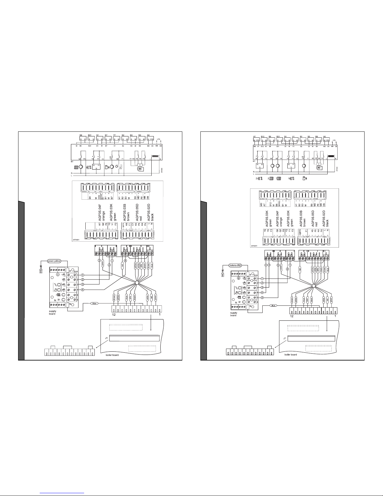
38
39
Schematics of the boiler KLO / KLO EKO and thermostat
RVA63.280
Schematics of the boiler KLO / KLO EKO and thermostat
RVA 63.242
 Loading...