


Floorstanding cast iron boiler
Cascade conection possible
Output up to 150 kW
Grizzly
EN
verzion
XXXX - v.2 4/2005
Manual for instruction
and use of boiler
65, 85, 100, 130, 150 KLO
Protherm spol. s r.o.
Jurkovičova 45
909 01 Skalica
Tel.: 034 6966 101
Fax: 043 6644 017
www.protherm.sk

2
3
Dear Client,
You have just become an owner of a KLO /
KLO EKO (Grizzly) natural gas or propane gas fired cast iron boiler. We are confident that you will be satisfied with the
service this boiler will give you. However, you’ll have to comply with at least
minimum requirements when running
the equipment. Therefore please read
these Operating Instructions carefully
and comply with their guidelines.
Please pay careful attention to the following
important information:
1. The boiler with all its accessories must
be installed and used in accordance
with an installation design, all applicable
legal regulations, technical standards
and manufacturer’s instructions.
2. The boiler may be installed only in the
environment for which it has been designed and only in a correctly ventilated
room.
3. After installation, the boiler must be put
into operation by a service organisation
authorised by the manufacturer.
4. Please also contact authorised service
if you are experiencing any problems
with the equipment – unauthorised repairs may damage the boiler (as well as
the connected equipment!).
5. The service technician when putting
the boiler into operation for the fist time
must demonstrate its controls and show
you its various parts and how to control
them.
6. Check whether the boiler is complete.
7. Check whether it is the model you have
ordered.
8. Whenever you have any doubts how to
operate the boiler, find and study the
relevant information in these Operating
Instructions and proceed in accordance
with them.
In practice, situations might occur when the
following essential measures have to be
taken:
– prevent the boiler from being (even
accidentally) switched on while inspecting the fumes exhaust and gas
and water distribution routes, by disconnecting the boiler from power
supply by another means than just
with the boiler’s switch (e.g. by pulling the power cord plug out of the
socket),
– shut the boiler down every time when
flammable or explosive vapours are
present (even temporarily) inside
the premises from which combustion air is supplied to the boiler,
– if it is inevitable to drain water from
the boiler or the heating system, the
water must not be dangerously hot,
– when water leaks from the boiler’s
heat exchanger or when the exchanger is clogged with ice, do not try to
switch the boiler on until normal running conditions have been restored,
– during (even suspected) gas leaks or
after gas supply failure, switch the
boiler and the gas supply off and call
the gas company or authorised service.
Regulations and Directives
The PROTHERM KLO boiler may be
put into operation only by an authorised
service organisation in accordance with
UBP SR Notice No. 74/1996. Installations,
putting the boiler into operation, warranty
and post-warranty service are performed
by a network of the manufacturer’s contractual service organisations, which meet
the above-specified requirements. Installations must be carried out in accordance
with a design prepared in compliance with
applicable regulations detailed below.
9. When repairing the boiler, only original
parts must be always used. Internal wiring and factory settings must not be
changed or interfered with.
10. Do not remove or damage any signs
and labels on the boiler.
11. The boiler meets regulations applicable
in Slovakia. For use in other countries,
any potential differences must be identified and resolved.
12. At the end of life of the boiler’s parts and
components (or of the entire boiler), their disposal must be carried out ecologically – metal parts must be delivered to
a metal scrap yard, plastics, seals, and
insulation materials must be sorted out
as required, or a special disposal technology used, engaging the services of
companies authorised for such operations.
13. Before a protracted shutdown we recommend to turn off the gas supply and
disconnect the boiler from power supply.
This recommendation is part of general
conditions defined in this Operating Instructions.
15. The manufacturer shall not be held liable for any damages caused by the
user’s failure to:
– abide by the conditions defined in
these Operating Instructions,
– abide by applicable regulations and
standards,
– abide by installation and operating in-
structions.
– abide by the regulations specified in
the Warranty Certificate and Service
Book.
Such damages are not covered by the pro-
duct warranty.
a ) Heating systems:
STN 06 0310 – Central heating, design
and installations
STN 06 0830 – Safety equipment for central heating and hot water heating systems.
STN 07 7401 – Water and steam for heat
energy equipment of operating pressure
up to 8 MPa
b ) Gas distribution systems:
STN 38 6420 – Industrial gas pipelines.
STN EN 1775 – Gas supply – Gas pipelines in buildings – Maximum operating
pressure below 5 bar
STN 38 6413 – Steel gas pipelines and
connections
STN 07 0703 – Gas-fired boilers
STN 38 6405 – Gas equipment. Operating
principles.
Act No. 222/94 Coll. on business conditions and public service supervision in
the energy industry and on state energy
inspection.
c ) Electrical installation:
STN 33 2180 – Wiring of electrical instruments and appliances.
STN 33 2000-3 – Electrical installation in
buildings. Part 3: Definition of basic characteristics.
STN 33 2000-7-701 – Electrical installation in buildings. Part 7: Requirements on
special installations or premises. Section
701. Rooms with a bath-tub…
STN 33 2130 – Electrical engineering regulations. Interior electrical installations.
STN 33 0160 – Electrical engineering
regulations. Labelling terminals of electrical objects.
Execution regulations.
STN 33 0165 – Electrical engineering
regulations. Colour marking or numbering
of wires.
Execution regulations.
STN 33 2350 – Regulations for electrical
equipment in difficult climatic conditions.

4
5
STN 34 0350 – STN electrical engineering regulations. Regulations for loose cables and cords.
STN 33 1500 – Instructions for electrical
equipment.
STN EN 60 335-1 – Safety of household
and similar electrical appliances. Part 1
– General requirements.
d ) Chimney:
STN 73 4210 – Construction of chimneys
and fume exhausts and connecting fuel
appliances to them.
STN 73 4201 – Designing chimneys and
fume exhaust flues.
STN 06 1610 – Fume exhaust parts of
household appliances.
STN EN 297 – Gas-fired central heating
boilers. Boilers Type B11 and B11BS with
atmospheric burners and nominal thermal
output up to 70 KW.
e ) Fire protection regulations:
STN 92 0300 – Fire safety of local appliances and sources of heat.
STN 73 0823 – Fire technical properties
of materials. Degrees of flammability of
building materials.
f ) Utility hot water heating systems:
STN 06 0320 – Heating of utility hot water.
STN 06 0830 – Safety devices for central
heating and utility hot water heating systems.
STN 73 6660 – Internal water distribution
systems.
STN 83 0616 – Utility hot water quality.
Safety of Persons and Equipment
As products, boilers are verified for compliance with the following documents:
STN EN 437, STN EN 50165, STN EN
60335-1+A11, Act No. 513/1991 Commercial Code, Act No. 634/1992 and Ministry
of Health Public Notice No. 13/1977.
Boiler Features
The PROTHERM KLO / KLO EKO stationary, cast iron boiler is designed for heating
water for heating purposes and, if combined with an indirectly heated reservoir,
also for heating utility hot water. It is available in the following series of size:
a) 65, 85, 100, 130, 150 KLO
b) 65, 85, 100, 130, 150 KLO EKO
The boilers use as fuel natural gas and
both series have a dual-stage design (low
and high output).
Models 65 – 85 KLO/KLO EKO are single-stage and designed to run on propane
gas.
Both model series can be fitted with a Siemens Albatros RVA 43.222 equithermal
control unit. By combining it with other
RVA 43.222 control units, a cascade system can be created with multiple sources
of heat.
The central heating system water pump is
controlled by a thermostat and turned on
only when the heating water temperature
reaches a set value. This reduces the time
required to heat the water inside the boiler after a protracted break in the boiler’s
function. The heating water pump is part
of the delivery.
The boiler can work in conjunction with
an indirectly heated utility water tank. The
standard boiler configuration allows the
tank to be connected easily to the boiler’s
terminal box.
To guarantee correct functioning of the
system, we recommend using a PROTHERM reservoir heater of 95- to 200-litre
volume, equipped with a thermostat and a
switching contact. Using the RVA 43.222
control unit will allow water in the reservoir
to be topped up by a pump.
Important: For combined heaters (with
water heated also by electricity), it is essential to prevent the supply of alien volt-
The boiler (as well as its accessories)
complies with the type which has been
tested and certified by the Technical Testing Institute in Piešťany, SKTC-104, authorised to verify the compliance with the
requirements of the Slovak Bureau for
Standardisation, Metrology and Testing,
and the compliance with the technical requirements specified by Government Decrees Nos. 392/99, 393/99 and 393/99 as
set forth in Act No. 264/1999.
Hence the boilers (and their accessories)
meet the requirements of applicable technical and legal standards, a fact confirmed
in a “Certificate of Compliance” issued by
the manufacturer. Pursuant to applicable legislation, the Certificate is kept for
inspection and supervision authorities,
and for distribution purposes sufficient is
a written confirmation that the Certificate
has been issued.
When installing and using the boilers and
their accessories, other generally applicable documents must taken into account,
which also define requirements in addition
to those on the product itself, namely:
– in the areas of design and installation
(and maintenance and repairs): STN
06 0310, STN 06 0830, STN 07 0703,
STN EN 1775, STN 38 6413 and STN
38 6460, STN 73 4201and STN 73
4210, and Public Notice No. 48/1982
(in the wording of later regulations)
and binding work safety and health at
work regulations;
– . during transportation and operation:
STN 38 6405, Public Notice No. 718/
2002.
In addition to abiding with the requirements of these documents, it is necessary to proceed when using the boiler in
accordance with these Operating Instructions and other manufacturer’s documentation supplied with the boiler.
age to the boiler – i.e. the thermostat contacts must be separated from the heater’s
internal electrical wiring!!!
Utility hot water heating has priority before
heating water. This means that water in
the central heating (CH) system is heated
only after the utility hot water (UHW) has
been heated to the required temperature.
Setting this value above usual temperature (50-60°C) will result in longer heating
times and hence longer breaks in heating the building. The heating time will be
longer also when the boiler is set to low
output, or when the CH water temperature
is set too low.
Important: The boiler must not be used for
any other purposes than those described
in these Operating Instructions.
6
7
The PROTHERM KLO boiler consists of
the following components:
1. cast iron body of the boiler with thermal
insulation and water connection pipe section;
2. burner plate with gas connection route
and ignition device;
3. collector of combustion fumes with a
chimney thrust detector and SKKT thermostat.
4. boiler covers with control panel and
boiler terminal box;
5. boiler base.
The cast iron boiler body is made of seg-
ments and serves as a combustion chamber (including combustion fumes routes),
and also as a water reservoir (including
water routes). The segments are lateral
(right and left) and central (one kind). The
boiler body of the required size (including
combustion chamber and water reservoir)
is constructed by assembling and joining
together the segments. The assembled
boiler body is fitted with pipe sections for
water connection and is insulated against
heat loss and heat radiation. It also has
960
850
52
544
92
125
370
605
720
1195
A
B
75
111
Æ G 6/4"
G
1"
Æ G 6/4"
C
Æ D
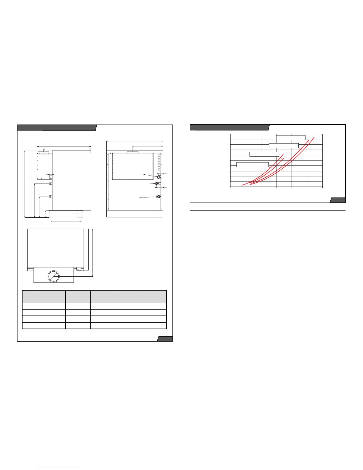
770
objemový prùtok vody V (m /h)
3
tlaková ztráta p (Pa)
20000
18000
20
0
4681012
16000
14000
12000
10000
8000
6000
4000
2000
65, 85 KLO / KLO EKO
100 KLO / KLO EKO
130 KLO / KLO EKO
150 KLO / KLO EKO
Model 65 KLO /
KLO EKO
85 KLO /
KLO EKO
100 KLO /
KLO EKO
130 KLO /
KLO EKO
150 KLO /
KLO EKO
A 850 1010 1170 1410 1570
B 460,5 540,5 620,5 740, 5 820,5
C 860,3 850,3 840,3 825,3 825,3
D 180 200 220 250 250
brackets for fitting thermostat sensors and
a thermometer, and lugs on feet for connecting the body to the boiler base. The
KLO EKO series boilers use low-emission
burner tubes, the KLO series boilers use
standard tubes. Depending on the output,
the boiler has 7 to 16 burner tubes and a
complete gas route.
The burner plate is fitted with a gas distribution section, the actual burner tubes
and an ignition device. The gas route
consists of a gas supply pipe section terminated with a combined gas valve. The
combined gas valve controls the supply
of gas into the boiler depending on the
required and reached operating states of
the whole system (i.e. the boiler combined
with the heating system); its outlet is already the gas distribution section of the of
the burner plate, terminated with 7 to 15
jets (one for each burner tube).
Igniting the burner and watching that it is
running is done by a Polidoro low-emission ignition burner. When a request is
sent to ignite the main burner, after waiting
time T
w
= 10 seconds, the ignition burner
Accessories
Pressure loss (Pa)
Fig. 1
Basic and Connecting Dimensions
Pressure loss of the boiler´s body
Fig. 2
Flow of water volume V (m3/h)

8
9
is automatically ignited. It is ignited by an
ignition spark and its flame is detected by
an ionisation electrode. After the ignition
burner has steadied up and the ionisation
circuit closed, the main gas supply valve
to the main burner opens. If the ignition
burner does not ignite within a safety time
T
s
= 25 seconds, the gas supply to the
main burner and to the ignition burner is
automatically shut off. If the flame during
normal boiler operation goes out, the automatic ignition system will repeat the ignition cycle of the ignition burner. If the loss
of ionisation prevails, the boiler will switch
to a fault status (the light of the “Unlock
automatic fault signalling system” button
on the control panel lights up). After a
waiting time of approximately 10 seconds,
the fault status can be manually cancelled
by pressing the RESET button.
The ignition burner remains on while the
main burner is on.
In the event of power supply failure, the
gas supply to the burner is automatically
shut off. When power supply is restored,
the boiler will automatically restart itself.
KLO
1
2
3
4
5
6
7
8
10
9
11131415
16
18
22
20
21
19
2
3
4
5
6
7
8
10
9
12131415
16
18
19
20
1
21
22
11
17
17
1. Main control panel
2. Chimney thrust detector system cover
3. Fume exhaust
4. Chimney thrust detector
5. Fume thermostat
6. Heating water outlet
7. Gas supply
8. Cast iron body segments
9. Heating water inlet
10. Combustion chamber
11. Secondary air supply
12. Supply burning air
13. Burner
14. Supply burning air
15. Jet
16. Combining pipeline gas
17. Operator burner
18. Gas armatures*
19. Boiler covering
20. Case for sensors
21. Main control panel
22. Automotive ignition
automatics
* For models 130-150 KLO / KLO EKO is used only 1 gas armature.
KLO EKO
KLO
The combustion fumes collector is connected to a chimney thrust detector and
behind it is terminated in a boiler exhaust
outlet (on a fumes flue connection). The
collector is equipped with a removable
cleaning lid, which is accessible after removing the top boiler’s cover.
The chimney thrust detector system
(SKKT) works on the principle of monitoring the combustion fumes temperature
inside the collector. A thermostat situated
inside the collector reacts to an increase
of the combustion fumes temperature
caused by a reduced chimney effect will
shut the boiler down (by shutting off gas
supply to the burner).
The boiler has covers, which are rigidly
fixed to the rear and side-wall, a removable wall and a removable top cover. The
boiler’s control panel is located in the top
section.
The boiler body base is a single steelbase on which the body of the boiler and
the covers are mounted.
Boiler Installation Guidelines
The PROTHERM KLO / KLO EKO boilers can be put into operation only by an
authorised service organisation in accordance with UBP SR Public Notice No. 74/
1996. Installations, putting into operation,
warranty and post-warranty service are
done by a network of manufacturer’s contractual service organisations, which meet
the requirements specified above.
Connecting the boiler to gas supply
The PROTHERM Series KLO - ZP / KLO
EKO – ZP boilers are designed to run on
natural gas with nominal pressure in the
distribution network 1.8 kPa (18 mbar) and
a calorific value usually claimed between
9 and 10 kWh/cum. The internal gas distribution system as well as the gas meter
must be of sufficient size, taking into account also other user’s gas appliances.
The gas supply pipe must have an internal
diameter of at least the same size as the
gas connection pipe on the boiler (which
depends on the boiler size), but preferably
one size bigger.
The PROTHERM Series 65 – 85 KLO - P /
65 - 85 KLO EKO - P boilers are designed
to run on propane gas. Propane gas calorific value is given between 12.8 and 13
kWh/kg. Because supplying boilers from
pressure cylinders is problematic, particularly from the capacity and handling point
Fig. 3
Schematic operation diagram

10
11
of view, it is recommended that a reservoir
is installed near the building to be heated,
and refilled by an authorised organisation.
Adequately sized propane supply from
the reservoir to the boiler and to other gas
appliances will then be part of the design
and delivery of the reservoir. When installing a propane gas-fired boiler, an accurate
nominal pressure of 3.0 kPa (30 mbar)
must be secured by installing a reduction
valve (station) before the boiler.
Supply of combustion air
Ventilation must guarantee that sufficient
quantity of combustion air is supplied to
the boiler and that the maximum permissible concentrations of harmful gases
in the boiler’s vicinity are not exceeded
and that an acceptable temperature is
maintained there (all in accordance with
Ministry of Environment Public Notice No.
706/2002).
The stationary cast iron PROTHERM
KLO/KLO EKO boilers draw combustion
air from the space in which they are installed. The combustion air supplied to the
boiler must be free of dust and corrosive
and flammable substances (vapours, solvents, paints, adhesives, etc.). The supply of adequate quantity of combustion
air must meet the requirements of STN
070703 “Gas-fired boiler rooms”. Gas appliances connected to combustion fumes
flue must not be located in places where
negative pressure can be created by ventilation fans.
Combustion fumes exhaust
The boiler is designed for combustion
fumes to be removed into a chimney (via
a chimney connection point) with a stabilised thrust of at least 2 Pa. The boiler is
connected to the chimney by a flue of a
diameter corresponding to the flue diam-
quired by the water composition. Depending on the anticipated amount of sludge
trapped; is recommended to desludge the
boiler approximately a week after it has
been put into operation. Functional defects
caused by mechanical dirt are not covered
by the manufacturer’s overall warranty (refer to Warranty Terms and Conditions).
Important: When filling the boiler with
water, all air in the boiler as well as in
the heating system has to be thoroughly
bled.
Using antifreeze liquid
KLO and KLO EKO boilers may be filled
with an antifreeze liquid, namely product
called ALYCOL TERMO, produced by
Slovnaft Moravia. Using other antifreeze
products will invalidate the manufacturer’s
warranty on parts and related costs.
Properties of the heating system
and filling the system with water
The boiler must be connected to the heating system distribution pipes (G6/4”) and
to the gas supply pipe (G 1”) in such a way
that the connection end pieces are not
stressed by forces imposed by the heating system distribution pipes or by the gas
supply pipe. The connection end pieces
have an external thread.
We recommend equipping the connection
eter of the flue connection point (depends
on the boiler size). The flue is part of the
delivery.
It is forbidden to put inside the flue objects
obstructing the flow of combustion fumes
(e.g. various types of heat exchangers to
increase utilisation of the heat).
Construction of the flue and the chimney
must comply with STN 06 1610, STN 73
420 and STN 73 4201 standards.
By complying with requirements of these
standards, we prevent undesirable phenomena from occurring, such as excessive cooling of the fumes, penetration of
dampness into walls, fluctuations in the
chimney effect (thrust) and thus undesirable effects on the boiler’s functioning.
Requirements on heating water
quality
The PROTHERM KLO / KLO EKO boilers
are designed for heating water of up to
400 kPa (4 bar) gauge pressure, which is
in compliance with STN 07 7401.
The first fill as well as top up water must
be clear and colourless, and be free of
suspended substances; oil and chemically corrosive additives, under no circumstances may be acidic (i.e. have pH factor
greater than 7) and must have minimal
carbonate hardness.
For softening the first fill water can be used
trisodium phosphate or a one-off dose of
chelating agent.
It is recommended to install before the
boiler (i.e. to the return heating water pipe)
a sludge trap. Its design should allow the
device to be emptied in regular intervals
without draining a great deal of heating
water in the process. The sludge trap can
be combined with a filter, but the filter itself
would not provide adequate protection.
Both the filter and the sludge trap must
be checked regularly and cleaned, as re-
pipes with isolation valves, so that when
repairing the boiler it is not necessary to
drain water from the heating system.
The heating system should be designed
in such a way that a permanent circulation
of the heating water is possible at least
through some radiators.
The boiler does not have an expansion
vessel or a safety valve built in, therefore
these devices can be connected only to
an external system, designed in accordance with STN 06 0310 and safety features compliant with STN 06 0830.
The boiler can work in systems with both
an open and closed (pressurised) expansion vessel. However, when using the
boiler in systems with an open expansion
vessel, it is necessary to harmonise the
temperature setting of the emergency
thermostat (98°C) and limit the operation
range on the heating controls. This setting
must be done by authorised service only.
In open expansion vessels, correct water
level must be maintained (between the operating minimum and maximum). Closed
expansion vessels when being filled up
must be set according to the heating system.
For filling and draining purposes, the boiler
is equipped with a filling (draining) valve.
After being filled up, the system must be
thoroughly bled.
After reconstructions, in unsuitable building disposition, etc., the boiler may be
connected to the heating system and to
the gas supply by flexible hoses, but only
those designed for this purpose. When using flexible connections, these should be
as short as possible, protected against
mechanical and chemical stress and damage, and be always replaced before the
end of their life or before their parameters
deteriorate with new ones (as determined
by their manufacturer).
Fig. 4
 Loading...