

Page 1
.
E-MU Systems 1
Page 2

Operation Manual
© 2006-2007 E-MU Systems
All Rights Reserved
Software Version: 2.0.1 - PTSB4
E-MU World Headquarters
E-MU Systems
1500 Green Hills Road
Scotts Valley, CA 95066
USA
Asia Pacific, Africa, Middle East
Creative Technology Ltd
31 International Business Park
Creative Resource. Singapore 609921
SINGAPORE
2 Proteus VX Operation Manual
Europe
Creative Labs
Ballycoolin Business Park
Blanchardstown
Dublin 15
IRELAND
E-MU Japan
Creative Media K K
Kanda Eight Bldg., 3F
4-6-7 Soto-Kanda
Chiyoda-ku, Tokyo 101-0021
JAPAN
Page 3

Table of Contents
1 - Introduction & Installation ....................................... 9
Introduction ......................................................................................................................... 9
Proteus VX ..........................................................................................................................9
Before you Begin… .........................................................................................................9
Notes, Tips and Warnings ...........................................................................................10
System Requirements ......................................................................................................... 10
Software Installation ..........................................................................................................10
Programs installed .......................................................................................................10
Optimizing Your Computer for Proteus VX .................................................................11
Setting up Cubase LE4 and Proteus XVSTi ...................................................................... 11
Running Proteus VX VSTi from Cubase LE4 ................................................................... 13
On Your Own ..................................................................................................................16
Troubleshooting Checklist .............................................................................................17
No MIDI Keyboard Control? ......................................................................................17
No Audio? .....................................................................................................................17
Setting up the Preferences ................................................................................................. 18
Audio Preferences ..............................................................................................................19
Audio Setup .....................................................................................................................19
Use Optimal Buffer Size ..............................................................................................19
Buffer Size .....................................................................................................................19
Sample Rate ..................................................................................................................19
CPU Cap .......................................................................................................................19
Headroom/Boost .........................................................................................................20
Ultra-High Precision Interpolation Button ...............................................................20
VST Output Buses .........................................................................................................20
MIDI .................................................................................................................................20
MIDI Inputs ..................................................................................................................21
MIDI Response .............................................................................................................21
Controllers .......................................................................................................................22
Other Settings ..................................................................................................................23
Appearance Settings in Windows ..................................................................................24
Proteus VX Question & Answer ........................................................................................ 25
2 - Guided Tours .......................................................... 27
Exploring the Tree .............................................................................................................. 27
Multisetup Page .................................................................................................................. 28
Changing Presets (from Single View) ...........................................................................29
Channel 1-16 View .........................................................................................................30
Changing Presets (from the 1-16 view) ........................................................................30
Adjusting the Controllers ...............................................................................................31
Create Your Own Custom Bank ....................................................................................... 32
Save and Save As .............................................................................................................33
Proteus VX Bank Structure ..............................................................................................33
The Librarian ...................................................................................................................... 34
E-MU Systems 3
Page 4

3 - Multisetup / Global Controls ................................... 37
The Multisetup .................................................................................................................... 37
Changing Presets (from Single View) ...........................................................................38
16 Channel View .............................................................................................................39
Saving your Multisetup ...................................................................................................39
The Current MIDI Channel .........................................................................................40
MIDI Channel ..............................................................................................................40
Preset Assignment ........................................................................................................40
Channel Volume ..........................................................................................................40
Channel Pan .................................................................................................................40
Output Assignment ......................................................................................................40
Output View Button .....................................................................................................41
Aux FX View Buttons ....................................................................................................41
Aux Send On/Off .........................................................................................................41
Preset FX Enables .........................................................................................................41
Select Effect ...................................................................................................................41
TwistaLoop Override ...................................................................................................41
Global Controls .................................................................................................................. 42
Master Volume Control & VU Meter ..........................................................................42
Tempo Control .............................................................................................................42
Master Tune ..................................................................................................................42
Master Transpose .........................................................................................................42
Limiter ...........................................................................................................................42
Aux Outputs ..................................................................................................................43
Filter Override ..............................................................................................................44
Filter Descriptions ...........................................................................................................44
Filter Types ....................................................................................................................44
MIDI Controllers & Scribble Strips ............................................................................46
Preroll RAM Used .........................................................................................................46
CPU Meter ....................................................................................................................47
Number of Samples Playing .......................................................................................47
Current Channel ..........................................................................................................47
Working with Multisetups ................................................................................................. 48
Saving FX & Multisetups ..............................................................................................48
VSTi Multisetups ...........................................................................................................48
4 - Preset Editor .......................................................... 51
Preset Globals ..................................................................................................................... 52
Transpose & Volume .......................................................................................................52
Initial Controllers A-P .....................................................................................................52
Capture MIDI Controllers ..............................................................................................53
TwistaLoop Lock To Tempo ...........................................................................................53
Initial Tempo ...................................................................................................................53
Tuning Tables ..................................................................................................................54
Preset Modulators ...........................................................................................................56
Templates .........................................................................................................................56
Channel Lag 1 & 2 Rate ...............................................................................................57
Poly Key Timer .............................................................................................................57
Channel Ramp .............................................................................................................58
Preset PatchCords ........................................................................................................58
4 Proteus VX Operation Manual
Page 5

5 - Effects .................................................................... 59
Overview ............................................................................................................................. 59
Programming Effects .......................................................................................................... 60
Adding an Aux Effect in the Multisetup ........................................................................60
Adding an Effect to a Preset ............................................................................................61
Block Diagram of the Effects Routing ........................................................................62
FX Routing .......................................................................................................................... 63
Block Diagram of the Effects Screens .........................................................................63
Effects Overhead ..........................................................................................................64
Typical Effects Usage ....................................................................................................64
VSTi Bus Outputs .........................................................................................................64
Main Output Window ....................................................................................................... 65
Main Output Window .................................................................................................65
Proteus X Composer FX Template .................................................................................... 66
Aux FX Screen ..................................................................................................................... 67
Aux Effects .....................................................................................................................67
Preset FX Screen .................................................................................................................. 68
Preset Effects .................................................................................................................68
Preset FX Modulation Parameters .................................................................................69
Creating, Deleting & Reordering Templates .................................................................70
Effects Listing ...................................................................................................................... 72
Effects Descriptions ............................................................................................................ 72
Background: Reverb .....................................................................................................72
Reverb ...............................................................................................................................73
Early Reflections Reverb .................................................................................................73
Reverb Lite (mono) .........................................................................................................74
Chorus ..............................................................................................................................75
Background: Chorus ....................................................................................................75
Chorus / Delay ................................................................................................................76
Compressor .....................................................................................................................77
Basic Controls ...............................................................................................................77
Delay ................................................................................................................................79
Background: Delay .......................................................................................................79
Discrete stereo ..............................................................................................................79
Ping Pong, stereo ..........................................................................................................80
Ping Pong, mono L->R .................................................................................................80
Delay (BPM) ....................................................................................................................82
Early Reflections ..............................................................................................................83
1-Band Para EQ ...............................................................................................................83
4-Band EQ ........................................................................................................................84
Flanger ..............................................................................................................................85
Growl ................................................................................................................................86
Limiter ..............................................................................................................................87
Phaser ...............................................................................................................................88
Pitch Shifter (mono) .......................................................................................................89
Ring Modulator ...............................................................................................................90
SP12-ulator ......................................................................................................................91
Tremulator BPM ..............................................................................................................92
Tube ..................................................................................................................................94
Twin ..................................................................................................................................95
E-MU Systems 5
Page 6

6 - Controls ................................................................. 97
The Toolbars ....................................................................................................................... 97
Viewing and Hiding the Toolbars ..................................................................................98
Drag & Drop ....................................................................................................................... 98
Changing Settings ..............................................................................................................98
Entering Numeric Values ................................................................................................98
View Menu .......................................................................................................................... 99
Main Display View ....................................................................................................... 100
Tree View ....................................................................................................................... 100
Tree Navigation using the Keyboard .......................................................................... 101
Cursor Keys ................................................................................................................ 101
Find Items .................................................................................................................. 101
Refresh (F5) .................................................................................................................. 101
Context Sensitive Menus ............................................................................................. 101
Undo/Redo ................................................................................................................... 101
7 - Synthesizer Basics ................................................ 103
Editing Presets .................................................................................................................. 103
Modulation ....................................................................................................................... 104
Modulation Sources ..................................................................................................... 104
Keyboard Key ............................................................................................................. 104
Key Velocity ............................................................................................................... 104
Release Velocity ......................................................................................................... 104
Gate ............................................................................................................................ 104
Key Glide .................................................................................................................... 104
Pitch and Mod Wheels ............................................................................................. 104
Keyboard Pressure (mono aftertouch) ................................................................... 105
Pedal ........................................................................................................................... 105
Miscellaneous Controllers A -P ................................................................................ 105
Low Frequency Oscillators (2 per voice) ................................................................ 105
Envelope Generators (3 per voice) .......................................................................... 105
Function Generators (3 per voice) .......................................................................... 105
Noise & Random Generators ................................................................................... 105
T-switch and Footswitches ....................................................................................... 105
Modulation Cords ........................................................................................................ 105
Envelope Generators ........................................................................................................ 106
Retriggering ................................................................................................................ 106
Complete Mode ......................................................................................................... 106
Low Frequency Oscillators (LFOs) ................................................................................. 107
Random Sources .............................................................................................................. 108
Clock Modulation ............................................................................................................ 108
Syncing an LFO to the Clock .................................................................................... 108
Function Generators ........................................................................................................ 109
Modulation Destinations ................................................................................................ 110
Modulation Processors .................................................................................................... 111
Dynamic Filters ................................................................................................................112
What is a Filter? ......................................................................................................... 112
Parametric Filters ....................................................................................................... 115
The Z-Plane Filter ......................................................................................................... 116
MIDI Channels & Real-time Controls ............................................................................ 117
MIDI Program Change Commands ............................................................................... 119
MIDI Bank Select Commands ..................................................................................... 119
Background: Bank Select Commands ..................................................................... 119
MIDI Modes ...................................................................................................................... 119
6 Proteus VX Operation Manual
Page 7

8 - Appendix ............................................................. 121
Keyboard Shortcuts .......................................................................................................... 121
Right Click Shortcuts ....................................................................................................... 121
Toolbar Functions ............................................................................................................ 122
MIDI Implementation Chart .......................................................................................... 123
MIDI Implementation Chart (part 2 - Controllers) ............................................... 124
Special Notes: ............................................................................................................ 127
Controller Functions .................................................................................................... 128
Index ........................................................................ 129
E-MU Systems 7
Page 8

8 Proteus VX Operation Manual
Page 9

1 - Introduction & Installation
Introduction
The Proteus VX is a professional desktop sound module based on the Proteus sound
modules and Emulator samplers. The engineers and designers at E-MU Systems have
brought their years of experience and expertise together to create the most comprehensive and flexible software instrument ever.
Proteus VX uses the renowned Emulator 4 Ultra/Proteus 2000 synthesis architecture as
its synthesis engine. Although not all the modules are user-programmable in the VX
version, they are working behind-the-scenes to provide you with truly awe-inspiring
sound.
Proteus VX
Proteus VX allows quick and easy creation of multitimbral setups on up to 16 different
MIDI channels. The Proteus VX sound engine contains the following features:
1 - Introduction & Installation
Introduction
• 24-bit playback
• Up to 192 kHz sample rate
• 32-bit floating point internal processing
• Drag and drop preset selection
• Phase Locked Stereo signal path
• Ultra High Precision Pitch Interpolation (user selectable)
• High Voice Polyphony (system dependent)
• Real-time controllers for all important control points
• 54 different filter types including multi-pole resonant filters, phasers, flangers, vocal
filters and multi-parameter morphing filters.
Note: The following features are not user-programmable in Proteus VX.
• Extremely powerful voice and sample zones can be crossfaded by position, velocity
or real-time controller up to 128 layers deep.
• Three multi-stage envelopes, three 64-stage function generators, two lag
processors and two multi-wave LFO’s per voice.
• Super-flexible PatchCord modulation matrix allows any modulation source to be
connected to any destination.
Before you Begin…
You should have a good working knowledge of your computer’s operating system. For
example, you should know how to use the mouse, standard menus and commands.
You should also know how to cut, copy, paste, open and close files.
E-MU Systems 9
Page 10

1 - Introduction & Installation
System Requirements
Notes, Tips and Warnings
Items of special interest are presented in this document as notes, tips and warnings.
Notes provide additional information related to the topic being discussed. Often,
notes describe the interaction between the topic and some other aspect of the
system.
Tips describe applications for the topic under discussion.
War n ings are especially important, since they help you avoid activities that can
cause damage to your files, your computer or yourself.
System Requirements
To use Proteus VX you will need at least:
• Pentium III 1GHz or equivalent CPU (P4, 2 GHz or faster recommended)
• 512 MB RAM (1 GB DDR or greater recommended)
• Windows XP or Windows Vista
• (optional) A VST host application capable of running VST instruments (VSTi)
Software Installation
Programs installed
• Proteus VX standalone application
• Proteus VX VSTi application (virtual instrument used in a host sequencer application)
• Proteus X Composer Sound Bank
1. Insert the CD or DVD labeled E-MU Audio Production Tools into your CD-ROM
drive.
2. If Windows AutoPlay mode is enabled for your CD-ROM drive, the CD starts
running automatically. If not, from your Windows desktop, click Start->Run and
type d:\setup.exe (replace d:\ with the drive letter of your CD-ROM drive).
3. The installation splash screen appears. Check the box labelled, Install Proteus VX
and click OK.
4. Follow the instructions on the screen.
The Proteus VX applications have been installed inside “Program Files/Creative
Professional/ProteusVX.”
5. Look for any “ReadMe” files in the Proteus VX folder or in the Start menu and read
these before continuing. The readme files may contain important last minute
information that didn’t make it into this manual.
6. Remove the E-MU Audio Production Tools disk from the CD-ROM drive.
10 Proteus VX Operation Manual
Page 11
Setting up Cubase LE4 and Proteus XVSTi
Optimizing Your Computer for Proteus VX
Windows: The following suggestions can help you configure your windows machine
for optimal performance. Since systems vary, we recommend that you note the original
settings of any system parameters you alter so that you can restore them in the event
that unexpected problems occur as you seek to optimize your system for Proteus VX:
• Seriously consider dedicating a computer as your audio workstation. This
computer can be optimized for best audio performance.
1 - Introduction & Installation
• If possible, avoid assigning slower devices to the IDE controller used by your audio
drive.
• Get the fastest hard disk drive you can afford. Many drives now offer an 8MB 16MB data buffer, which can also improve performance.
• Defragment your hard drive often.
• Perform a “clean” install of your operating system with only the minimum components and programs installed.
• Use the System Restore feature of Windows XP or other restoration programs such
™
as “Norton Ghost”
to make backups of your system for easy recovery and system
maintenance.
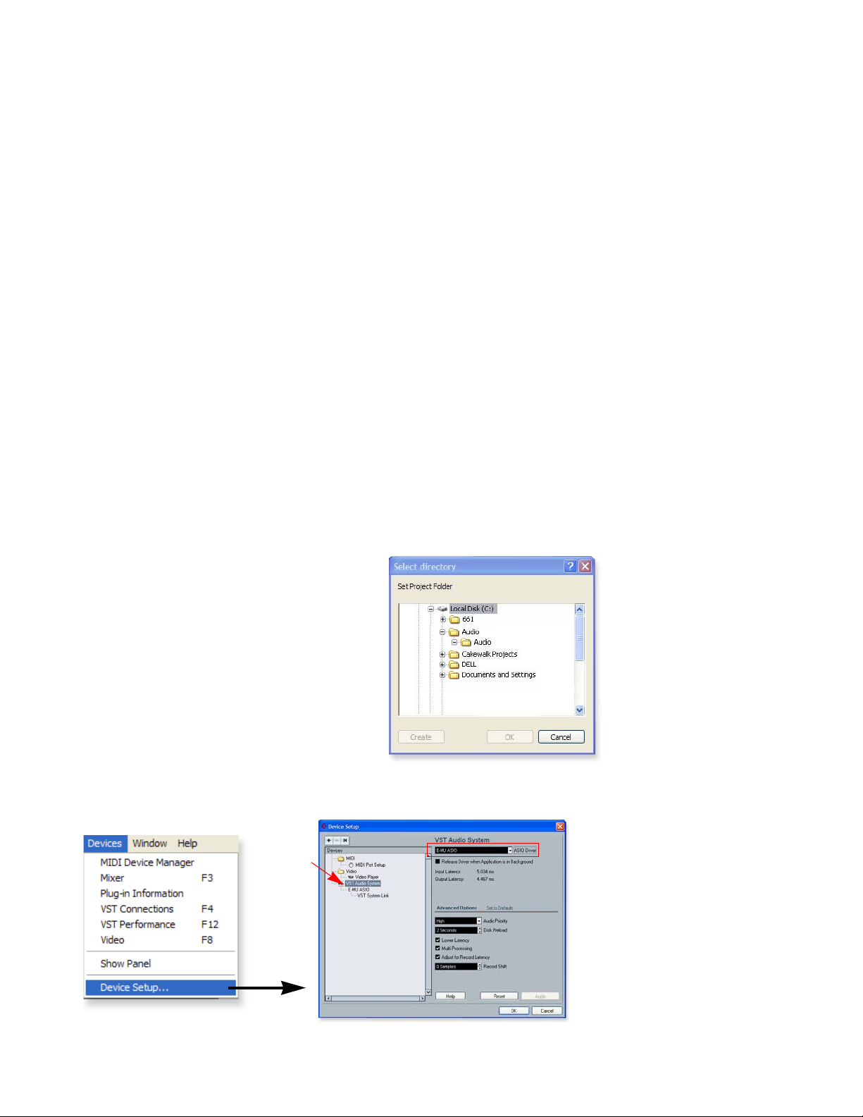
Setting up Cubase LE4 and Proteus XVSTi
Proteus VX VSTi is a VSTi (Virtual Studio Technology instrument) which means that it
“lives” inside of a VST “host”application such as Cubase LE. These instructions pertain
to Cubase LE 4 since it is supplied in the “E-MU Audio Production Tools” software
bundle. This information can be applied to other applications as well.
1. Open Cubase LE 4 from the Start menu. An
ASIO multimedia driver test dialog box will
pop up to ask if you want to run the ASIO
test. Choose No, because you won’t be using
the driver anyway.
2. Select New Project from the File menu.
3. Select Empty and click OK.
4. A Select Directory pop-up dialog box will
appear. Choose a location on your hard disk
where you want to store your audio files,
then click OK.
5. The Cubase LE 4 Project window appears.
Proteus VX is a
“Lite” version of our
standalone Proteus X2
and Emulator X2
products. Proteus VX
allows basic preset and
effects programming.
Proteus X2 provides
extensive synthesizer
preset programming.
Emulator X2 contains
all features of Proteus X2
and adds intelligent
sampling and a host of
powerful sample editing
features.
TIP . . .
If you have two or more
hard disks, it’s better to
store audio files on a disk
that isn’t running your
OS.
6. Select Device Setup… from the Devices menu.
Step 10:
VST
Audio
E-MU Systems 11
Page 12
1 - Introduction & Installation
Setting up Cubase LE4 and Proteus XVSTi
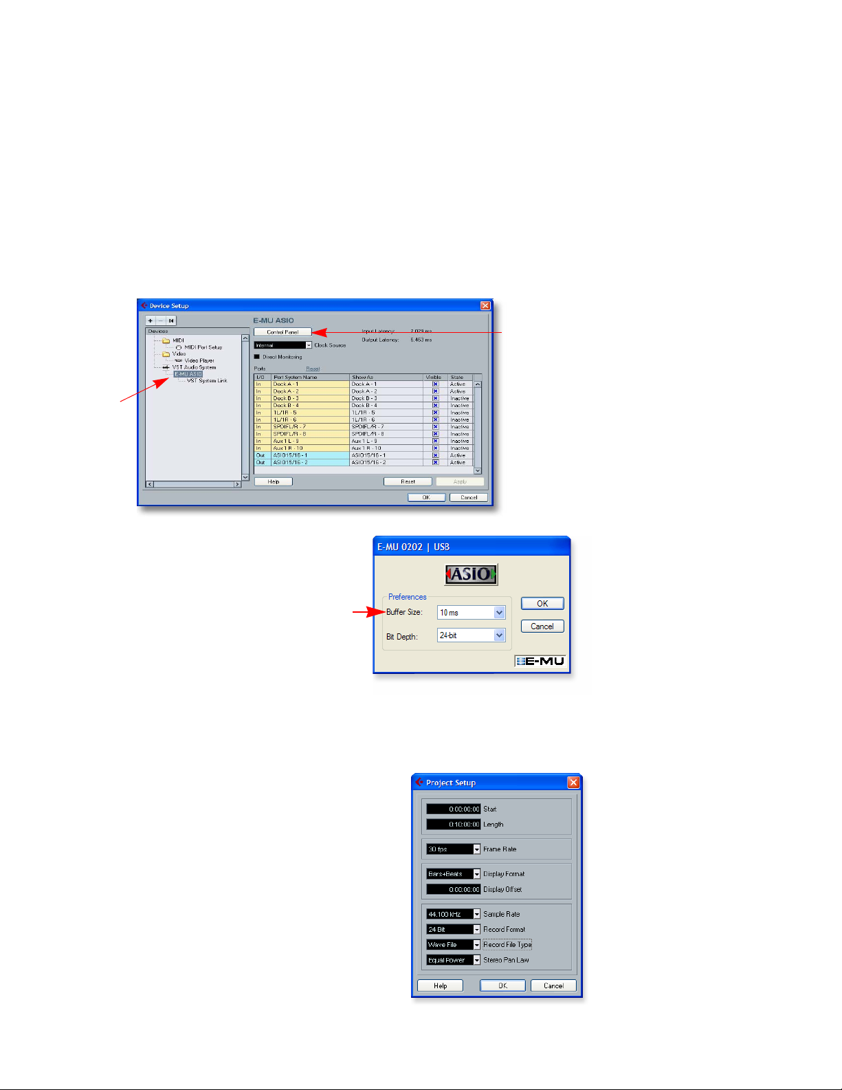
7. Select VST Audio System from the left pane.
8. Select the ASIO Driver. Choose your E-MU interface from the list. Choose:
E-MU ASIO (0404, 1212, 1820, 1616 Digital Audio Systems), ASIO E-MU
0404|USB, ASIO E-MU 0202|USB, or ASIO E-MU TRACKER Pre|USB.
9. A pop up dialog box asks you if you want to keep or switch the ASIO driver. Select
Switch.
Buffer Latency Setting
10. Click on the name of your E-MU interface that appears immediately below VST
Audio System in the Devices pane. Refer to the following screen.
Step 11
Control
Panel
Step 10
VST
Audio
WARNING!
DO NOT select the “ASIO
Multimedia Driver” or the
“ASIO Direct X Full Duplex
Driver.”
11. Click the Control Panel button. The
pop-up dialog box shown at right
appears.
12. Set the ASIO Buffer Latency as low as
your computer will allow and click OK.
(10ms is a good starting point.)
A low latency setting is important to
assure fast response when using virtual
instruments and to minimize delay
when monitoring through Cubase. If
you hear crackles or other audio
problems, try increasing the Buffer Size.
13. Close the Device Setup screen by clicking OK.
Setting up a New Project
14. Select New Project from File menu in Cubase LE
4. A pop-up Template selection dialog box
appears. Select Empty, then click OK.
15. Another pop-up dialog box appears asking you
to select the directory in which your audio files
will be stored. Choose a location to store your
audio files and click OK.
NOTE
E-MU 0202 Control Panel
is shown at left. The Bit
Depth field does not
appear with 0404PCI,
1212, 1820 or 1616.
WARNING!
If the Cubase LE 4 application crashes for any
reason, it is recommended that you re-boot
the computer.
16. Select Project Setup (Shift +S) from the Project
menu. This is where you set the Sample Rate and
Record Format (bit depth), among other things.
Set the Record Format to 24 Bit and the Sample
Rate to 44.100 kHz.
12 Proteus VX Operation Manual
Page 13
Running Proteus VX VSTi from Cubase LE4
Optional - Add Additional Input Busses
If you are using an audio interface that has more than two inputs (0404 USB, 0404,
1212, 1616, 1820), the following instructions will allow you to select these extra inputs
to feed your audio tracks.
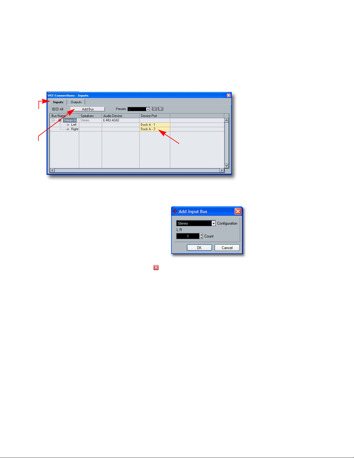
17. Select VST Connections (F4) from the Devices menu.
Step
18
1 - Introduction & Installation
Step
19
PatchMix Inputs
18. Select the Inputs Tab, revealing the window shown above.
19. Click the Add Bus button. The pop-up dialog
box shown at right appears.
20. Select the number of mono or stereo input
busses you want, then click OK.
21. Additional mono or stereo busses appear in the
list. Note that the actual PatchMix input label
appears in the Device Port field.
22. Close the window by clicking the close box. The inputs you added will now be
available for selection in the Track Input field of the Inspector pane.
Running Proteus VX VSTi from Cubase LE
4
These instructions explain how to start Proteus VX from within Cubase LE 4. If you
have a MIDI keyboard, you should connect it now using the setup diagrams and
instructions that came with your E-MU Audio Interface. Without a keyboard, you will
only be able to play one note at a time using the mini keyboard on Proteus VX.
You’ll need a MIDI interface and a MIDI keyboard (or other MIDI input device) for
this tutorial. Please refer to the Proteus VX manual for the complete set of instructions
(located under the Help menu item).
TIP . . .
You can also Rename your
Input Busses here to avoid
confusion when assigning
Inputs to tracks.
Make the Connections
1. Connect the MIDI out of your MIDI keyboard to the MIDI input of your MIDI
interface.
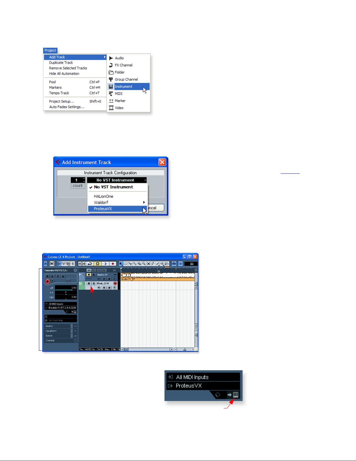
2. From the Project menu, select Add Track, Instrument.
E-MU Systems 13
Page 14
1 - Introduction & Installation
Running Proteus VX VSTi from Cubase LE4
3. A pop-up dialog box appears asking you to select a VST Instrument. Select Proteus
VX. Select a Count of 1. Click OK.
After a short delay, the Cubase Project Window should now look more or less like
the one below with one or more Audio tracks and one Instrument track:
NOTE
Selecting a Count of 2 or
more, instantiates multiple
copies of Proteus VX, which
results in very inefficient
usage of your CPU. (See the
note on page 16
NOTE #2
If you have Proteus X or
Emulator X, you can select
these in place of Proteus
VX.
.)
Instrument
Track
The Inspector
Open VX & Load a Bank
4. Since Proteus VX uses samples as the basis of
its sound, you need to load a bank of samples
before it can be played. The Edit Instrument
button, located in the Inspector section of the
window, allows you to edit the virtual
instrument.
Edit Instrument Button
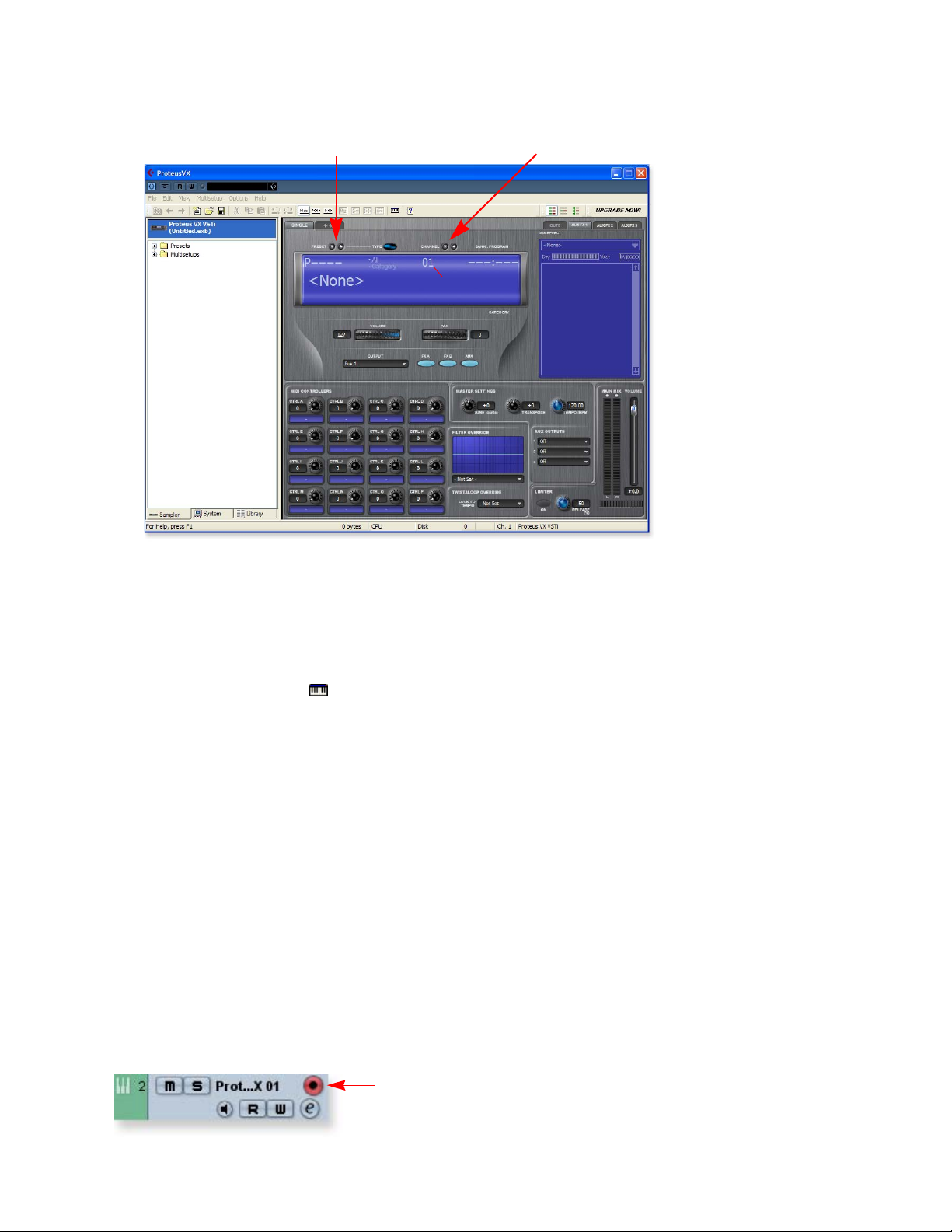
5. Click the Edit Instrument button. The Proteus VX main window appears.
14 Proteus VX Operation Manual
Page 15
MIDI Channel SelectionPreset Inc/Dec Keys
MIDI Channel
1 - Introduction & Installation
Running Proteus VX VSTi from Cubase LE4
6. Now we can load the Proteus X Composer bank. Select Proteus X Composer from
the File menu. The bank is installed here: “Program Files\Creative Professional\EMU Sound Central\Proteus X Composer.” Loading takes a few seconds.
7. Change the Preset using the Inc/Dec keys. You also have to select a preset before
you can hear anything. There are 1024 different presets (sounds) in this huge
bank.
8. Bring up the mini keyboard by clicking the icon on Proteus VX and play a few
notes. You should be hearing sound.
• If the sound volume is very low, you can decrease the Headroom of Proteus VX.
(Options, Preferences, Headroom/Boost) Keep in mind that with less
headroom, the Proteus VX will be more prone to clipping when multiple
channels are played.
9. Play your MIDI controller and verify that it plays Proteus VX. If not, check to
make sure your MIDI keyboard is set to the same MIDI channel number as Proteus
VX (probably channel 1).
10. Try out the MIDI Controller knobs on your MIDI keyboard. In order for these to
work, the continuous controller numbers of your keyboard knobs must match
those on Proteus VX. (Options, Preferences, Controllers tab).
11. Feel free to play around for awhile and don’t worry about losing anything.
Nothing is made permanent until you Save the bank, so have fun.
To Record a MIDI Track
TIP . . .
Increase the headroom
setting (more positive) to
increase the volume and
decrease the amount of
available headroom.
12. Make sure the Record Enable button on the MIDI track is on (it should be on by
default).
Record Enable
E-MU Systems 15
Page 16
1 - Introduction & Installation
Running Proteus VX VSTi from Cubase LE4
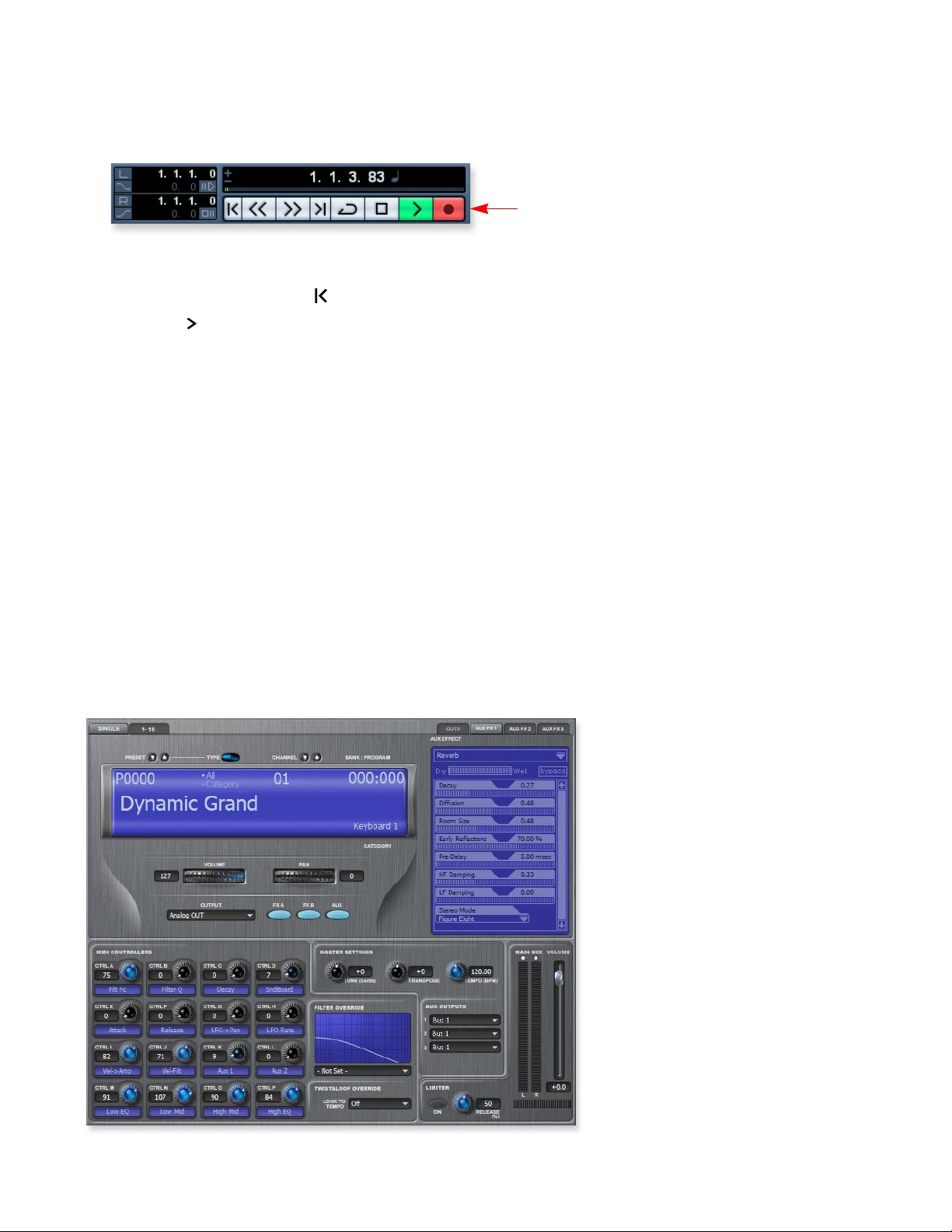
13. Click Record on the Cubase LE Transport control and start playing your MIDI
controller.
Record
14. Press Stop when you’re finished recording the first track.
15. Press the Go To Start button.
16. Press Play on the Cubase Transport to play back your track.
To Record a MIDI Track on another MIDI Channel
NOTE: Proteus VX VSTi can play back up to 16 MIDI tracks at once, however, the LE
version of Cubase 4 only supports a single MIDI channel per VSTi. You could load
another instance of the Proteus VX for each channel, but this is a very inefficient usage
of your CPU resources and is NOT recommended. The full version of Cubase 4 does
support multiple MIDI channels on a single VSTi.
Program Changes
Cubase LE 4 allows you to insert MIDI Program Change messages in the MIDI
sequence. (Key Editor, List Editor, Insert Program Change) This trick makes it possible
to use more than one Proteus VX preset in a song.
On Your Own
Feel free to play around for awhile and don’t worry about losing anything. Nothing is
made permanent until you Save the bank, so have fun. When you’re ready, look over
the rest of this manual. If you want a tour of the Proteus VX, be sure and check out
Chapter 2 - Guided Tours.
Proteus VX
Main Window
16 Proteus VX Operation Manual
Page 17

Running Proteus VX VSTi from Cubase LE4
Troubleshooting Checklist
No MIDI Keyboard Control?
• Is the MIDI Track input set to the proper MIDI port?
• Does the MIDI indicator on Cubase SE light up when you play?
• Check the Cubase LE “Devices” menu
No Audio?
• Do you see activity on the Main Mix meters of Proteus VX when you play the mini
keyboard?
• Is your audio device selected in the Proteus VX Preferences?
1 - Introduction & Installation
E-MU Systems 17
Page 18
1 - Introduction & Installation
Setting up the Preferences
Setting up the Preferences
The preferences dialog box contains a variety of important controls used to configure
Proteus VX for your audio hardware and to customize the controls to suit the way you
work.
To Access the Preferences Dialog Box
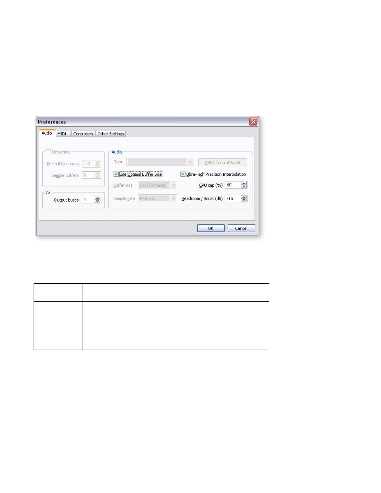
1. Select Preferences from the Options dialog box. The following screen appears.
2. The preferences dialog box is divided into four main groups. Click on the tab
heading to select one of the four sets of controls.
Audio
MIDI
Controllers
Other
Audio Hardware Setup & Pitch Shift Algorithm selection, number of
VST Output buses.
Receive/Ignore Program Changes, Internal/External Tempo Source
select, Velocity Response Curve, Volume Curve, Volume Sensitivity
This section allows you to set up the MIDI Continuous Controllers
you want the Proteus VX to receive.
Clear clip indicators after 10 seconds
18 Proteus VX Operation Manual
Page 19
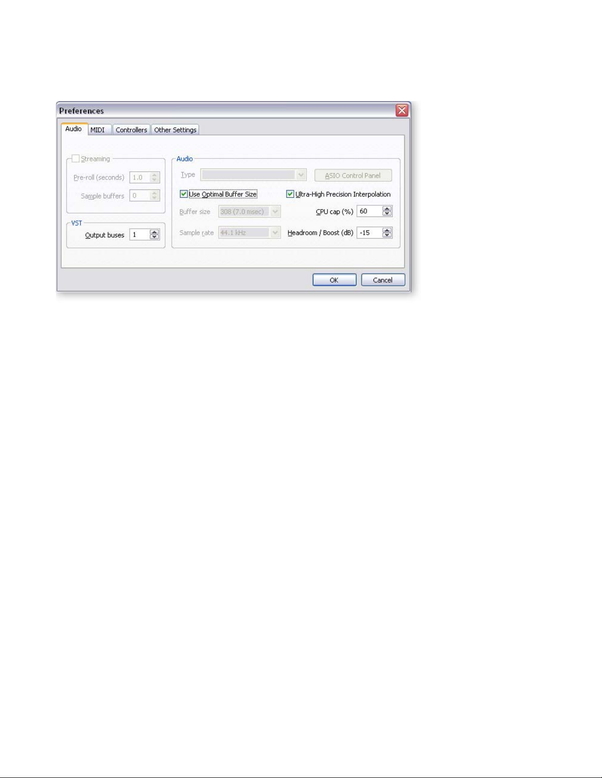
Audio Preferences
1 - Introduction & Installation
Audio Preferences
Audio Setup
These controls let you set audio quality parameters related to Proteus VX and your
sound card.
Use Optimal Buffer Size
When this box is checked, the Proteus VX will choose the best buffer size based on the
ASIO Buffer Latency setting (located in the ASIO control panel). You should normally
leave this feature enabled for best audio performance. In certain rare cases you may
want to manually set the buffer length to improve MIDI or synth performance.
Buffer Size
This control sets the number of sample periods between updates of the synthesizer
parameters. The buffer size can be adjusted according to the speed of your computer’s
CPU. A faster CPU can handle a lower buffer size. The default buffer size changes with
the latency setting when “Optimal Buffer Size”is checked.
Sample Rate
This control displays the output sample rate of the Proteus VX, and will always match
the sample rate of your sound card. The default setting is 44.1kHz.
CPU Cap
This important control sets the percentage of CPU resources that will be used by
Proteus VX and consequently the maximum number of samples that can be played at
the same time. Depending on the design of the preset, a single Proteus VX voice may
contain multiple samples which play simultaneously. The maximum setting is 80%
CPU usage. If you hear notes being “stolen” in your sequence or as you play the
keyboard, or if the disk meter readout at the bottom of the window goes into the red,
increase the value of this control. If you have other applications running, you may
want to reduce the setting of this control to free up more CPU for them.
Warning: Sounds
with long release times
will exhibit “voice
stealing” more than short
percussive sounds.
Tip: When running
multiple VSTi’s, distribute
the CPU Cap among the
VSTi’s. Example: If one
VSTi does not glitch at
60%, set the CPU Cap of
two VSTi’s so they add up
to 60%.
E-MU Systems 19
Page 20
1 - Introduction & Installation
Audio Preferences
Headroom/Boost
Headroom is the amount of dynamic range remaining before clipping occurs.
The amount of headroom is adjustable from 12 dB to -30 dB in 1 dB increments.
A headroom setting of 12dB provides the hottest output level, (and the highest signal
to noise ratio) but may produce “clipping” if too many notes are played at once. The
default headroom setting is -7 dB, which maintains an excellent signal to noise ratio
while keeping a reasonable amount of headroom in reserve. If you hear the signal
clipping or breaking up, decrease the headroom value. In practice, you can think of
this control as adjusting the control range of the Master Volume control.
Ultra-High Precision Interpolation Button
This button allows you to select between E-MU’s ultra-high precision pitch shifting
algorithm or a lower quality pitch shifting scheme which uses fewer CPU resources.
If you are using presets with a sample placed on every key, as is the case on many
banks, you can switch high precision off to free up CPU with no penalty in audio
quality. No pitch shifting is occurring anyway. High quality pitch interpolation is only
needed when you are playing presets which have a few samples mapped across the
entire keyboard. In this case, the Proteus VX shifts the pitch of the available samples to
fill in the keyboard.
VST Output Buses
This setting allows you to add additional VST buses (stereo pairs). Proteus VX channel
outputs can be assigned to VST buses in the Multisetup, Output field. These outputs are
sent to the VST Mixer in your recording application. You must restart the VSTi for the
changes to take effect.
Unlike some VSTi’s, Proteus VX is multitimbral, able to play up to 16 MIDI channels at
once. It’s far more CPU-efficient to have multiple MIDI channels playing on one
instance of Proteus, rather than have multiple VSTi’s running. Using VST Output buses,
you can route each MIDI channel to a separate bus in Cubase.
Note: The “Audio
Type” and “ASIO Control
Panel” parameters cannot
be edited in Proteus VX.
They will always appear
“greyed-out”.
MIDI
This group of preferences allows you to set up the MIDI inputs, adjust the master MIDI
volume and velocity curves.
Note: The
“Intelliedit” feature is not
applicable to Proteus VX.
The field will always
appear “greyed-out”.
20 Proteus VX Operation Manual
Page 21

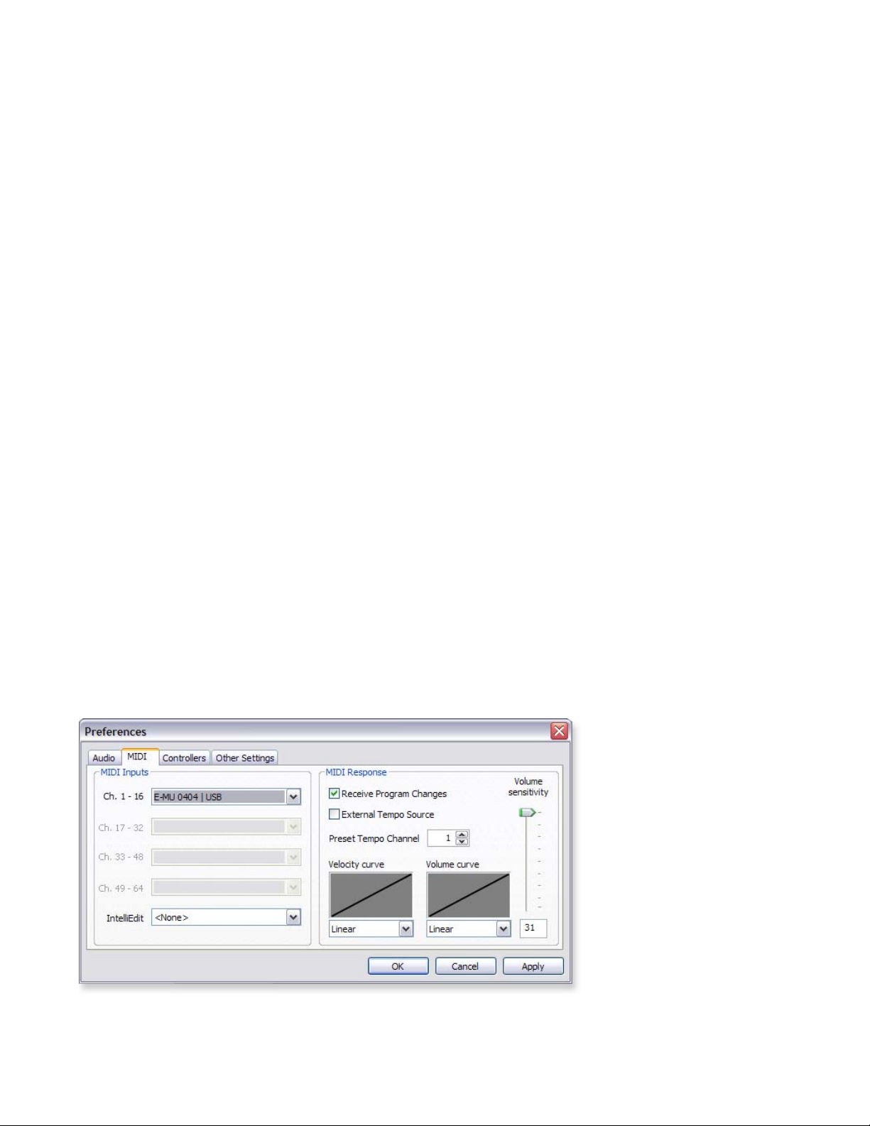
MIDI Inputs
Receive Program Changes
This check box selects whether or not MIDI Program Change messages from your MIDI
controller or sequencer will be received or ignored by the Proteus VX. Place an X in the
check box to receive program changes.
External Tempo Source
This check box selects between internal tempo clock or MIDI clock as the tempo
source. The Proteus VX uses a global master tempo for Tempo-based Envelopes,
Tempo-based LFOs, and clock modulation. When this check box is selected, MIDI
clock will be used for the global tempo and the tempo control in the Multisetup
window will be disabled.
Preset Tempo Channel
The tempo of Proteus VX can be specified in the preset so that selecting a preset on a
specific MIDI channel changes the tempo. This option selects the MIDI channel whose
preset will be used for Tempo Control. This feature allows the proper tempo to be set
when a Tempo-based or Twistaloop preset is selected.
For example, suppose you have this field set to channel 1 and the preset on MIDI
channel 1 has its Tempo Control set to 122.22 BPM. When the bank is loaded, the
Tempo will be set to 122.22 BPM. If you change the preset on channel 1, the tempo will
change to follow the “Initial Tempo” setting in the new preset. (See page 53
.)
1 - Introduction & Installation
Audio Preferences
Important!
If External Tempo Source
is set to external, the
tempo control in the
Voice Editor will be
“greyed-out” and nonfunctional.
If the preset on the Preset Tempo channel has its Tempo Control set to “Off”, (or if this
option is set to “Off”) no tempo change occurs when the preset is selected.
MIDI Response
These controls allow you to customize the MIDI response of the Proteus VX to match
your MIDI Controller or other instruments.
Vel ocity Cur v e
Incoming velocity values can be scaled by one of 24 curves to better adapt to your
playing style or MIDI controller. Selecting “linear” leaves the velocity data unaltered.
The shape of the selected curve is displayed in the window. Select the curve that feels
best with your MIDI keyboard.
Vol ume Curve
This is an adjustment to help match MIDI controller #7 volume response to other
manufacturers’ equipment. Three curves are provided: Linear, Inverse Square or
Logarithmic. The action of this control is displayed in the window.
Volume Sensitivity
This control allows you to modify the response curve for MIDI continuous controller
#7 (Volume). This allows you to match the Proteus VX’s response to other manufacturers’ equipment. Low numbers compress the volume control range, raising the
volume level at lower controller #7 values.
E-MU Systems 21
Page 22
1 - Introduction & Installation
Audio Preferences
Controllers
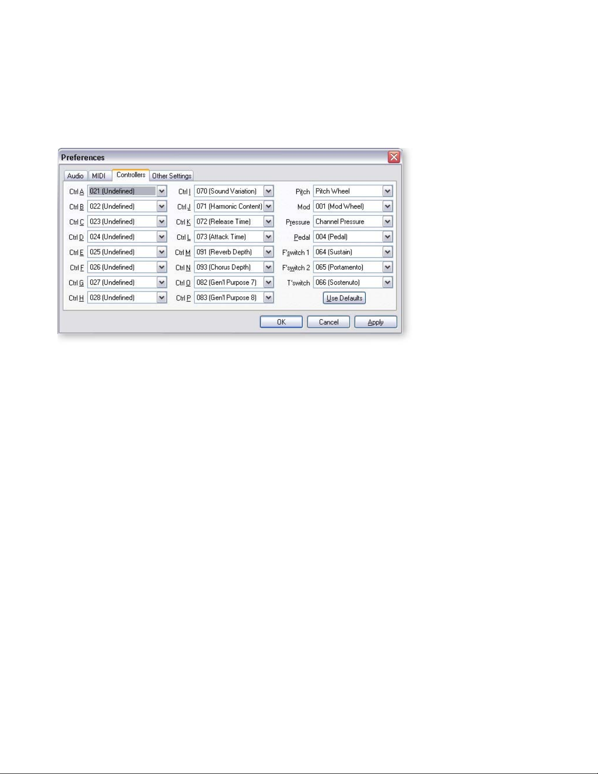
This is where you set up which MIDI Continuous Controllers the Proteus VX will
receive. Match these controls to the MIDI continuous controller numbers that your
keyboard or sequencer transmits. What the controllers actually do is pre-programmed
in each preset.
As you can see, MIDI Continuous Controller numbers are assigned to letters (A-P) or
labels (Pitch, Mod, Pressure, Pedal, etc.) in this screen. When a preset is programmed,
these letter or name labels are assigned to control various parameters such as filter
frequency or attack time.
The name labels such as pitch and mod wheels are so commonly used that they have
their own assigned name, but these can also be freely assigned in any way you choose.
If you’re just getting started, it’s probably best to use the default settings. Press the “Use
Default” button to restore the default settings which are shown above.
22 Proteus VX Operation Manual
Page 23
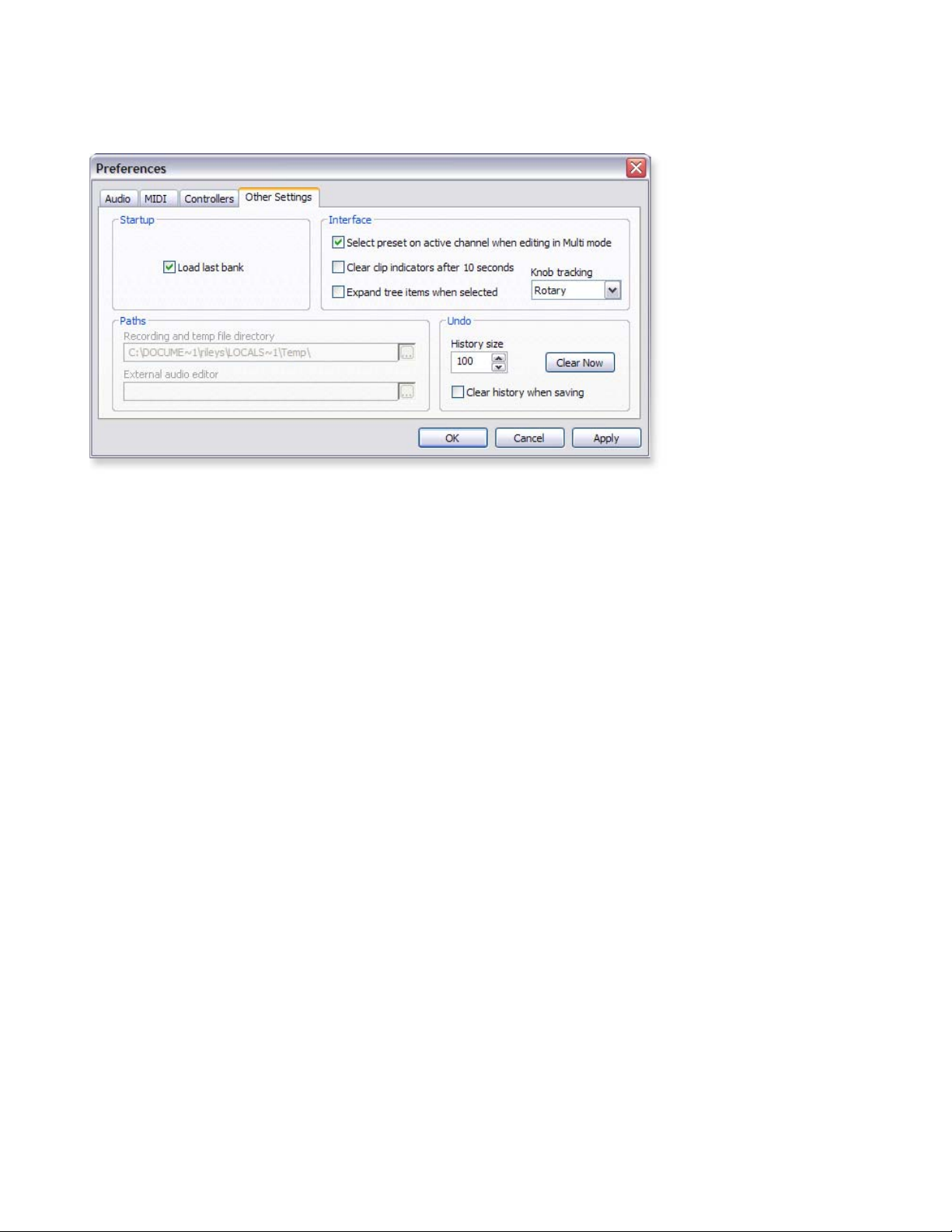
Other Settings
1 - Introduction & Installation
Audio Preferences
Startup
• Load last bank - This feature automatically loads the last bank you had loaded
whenever you start the Proteus VX application.
Interface
• Select preset on active channel when editing in Multimode - When checked,
selecting a preset for editing in the Tree selects that preset on the active channel
in the multisetup. This is what you want if you’re editing a preset and playing a
MIDI keyboard.
If you’re playing back a multi-timbral sequence and want to make a quick edit to
a preset, you might want this feature Off so as not to alter your multisetup.
• Clear clip indicators after 10 seconds - This feature automatically clears the
main output meter clip indicators. If this function is set to Off, the clip indicators
will stay on until you manually click on them.
• Expand tree items when selected - If this option is checked, selecting presets
from the Tree will automatically open the selected preset for editing. When
unchecked, selecting presets from the Tree will select the preset for playing, but
not open it for editing.
• Knob Tracking - This control allows the rotary knobs to be manipulated with
either Rotary, Horizontal, or Vertical motion. The setting affects all rotary
controls.
Undo
• History size - The maximum number of stored undo steps.
• Clear history when saving - Clears all undo history when you save a bank. If
you have this box unchecked, you can undo even when you save and re-open a
bank.
• Clear now - Clears the undo history immediately.
E-MU Systems 23
Page 24

1 - Introduction & Installation
Audio Preferences
Appearance Settings in Windows
Adjusting the “Performance Options” in Windows will make the Preference buttons
much easier to read and increase the smoothness when dragging windows around on
the screen.
To Improve the Appearance Settings:
1. Open the Windows Control Panel. (Start, Settings, Control Panel)
2. Select System.
3. Select the Advanced Settings tab.
4. Select Settings in the Performance section
5. Under Visual Effects, select Adjust for Best Performance.
6. Click OK.
24 Proteus VX Operation Manual
Page 25

Proteus VX Question & Answer
The Controller knobs on my keyboard don’t work with Proteus VX
A The controller numbers sent by your MIDI keyboard must match the controller
numbers that Proteus VX is receiving. See “
on page 117. Also see “Controllers”on page 22 to change the MIDI controllers
that Proteus VX receives.
There is a huge delay when I play Proteus VX from a MIDI keyboard
A Lower the ASIO Buffer Latency setting on your host application. An ASIO Buffer
setting of 10ms or below will be acceptable for most players.
Parts are cutting out in my sequence
A#1: You may be exceeding the capacity of your computer’s CPU. When multi-
tracking using VSTi’s and VST effects, it might be a good idea to “Render” or
“Freeze” the tracks to free up CPU resources.
A#2: You might try increasing the CPU Cap parameter in the Preferences menu
page 19). This setting controls the amount of CPU resources that Proteus VX is
(
allowed to use.
A#3: Turning Ultra High Interpolation Off in the Preferences menu frees up
CPU resources at the expense of audio quality. Use your ears to decide.
A#4: Are you running multiple instances of Proteus VX? Don’t. Proteus VX was
designed to be run as a single instance using multiple MIDI channels. Running
more than one instance of VX is extremely wasteful of your CPU resources.
MIDI Channels & Real-time Controls”
1 - Introduction & Installation
Proteus VX Question & Answer
Can I play SoundFonts with the Proteus VX?
A No, but the full versions of Proteus X2 (and Emulator X2) include a File Converter
program which converts SoundFonts to the Emulator format used by Proteus VX.
Can I play General MIDI files using the Proteus VX?
A No, but the full versions of Proteus X2 (and Emulator X2) include a General MIDI
bank. This bank will load into Proteus VX.
Can I send different MIDI channels to separate outputs?
A Yes. T h e VST Output Bus setting (page 20
), lets you add additional VST buses.
After additional buses are created, Proteus VX channel outputs can be assigned
to VST buses in the Multisetup, Output field.
How do I find out the number of samples used per note?
A Play a single note on the keyboard and look at the “Samples Playing” display at
the bottom of the window. Please refer to the diagram on page 28
.
E-MU Systems 25
Page 26

1 - Introduction & Installation
Proteus VX Question & Answer
26 Proteus VX Operation Manual
Page 27
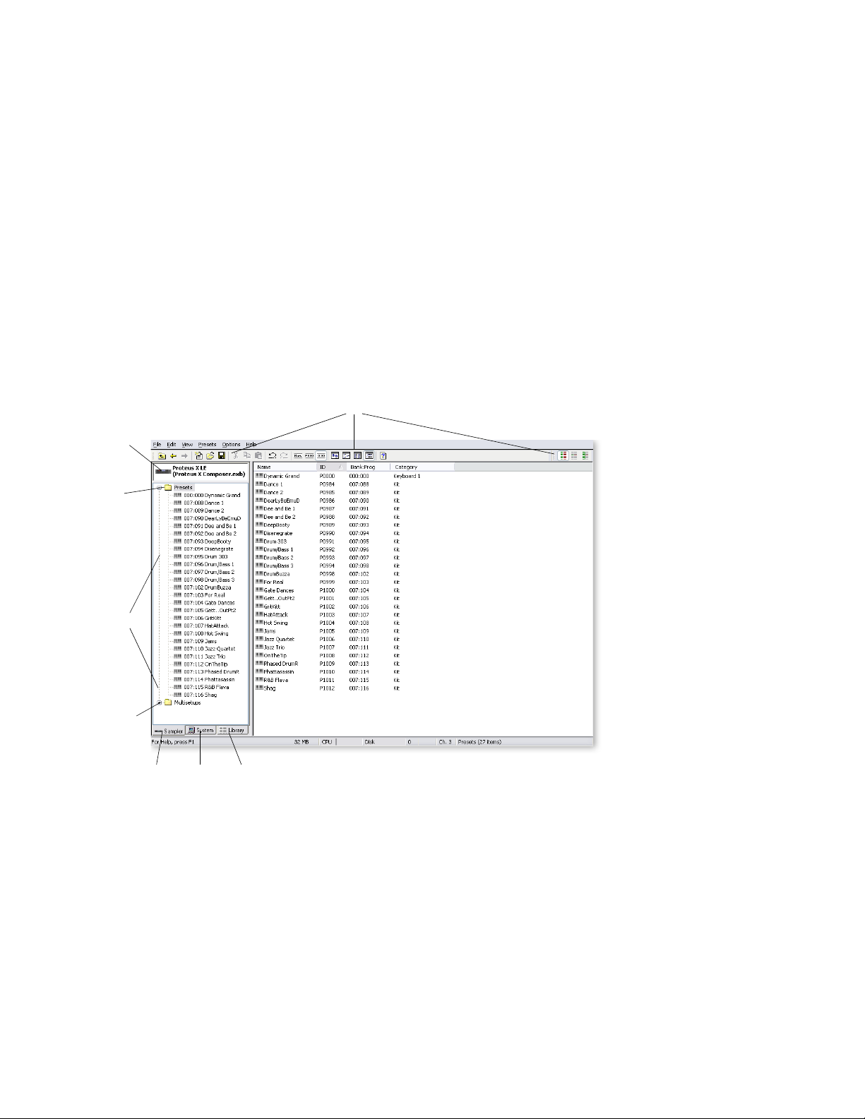
2 - Guided Tours
Exploring the Tree
In this section you’ll learn how to navigate around Proteus VX using the Tree. Don’t
worry if you don’t know what everything does just yet. All the details will be explained
later on.
1. With the Proteus VX application running, a bank is loaded by selecting Open from
the File menu. Click on the Presets Folder in the Tree and a screen, similar to the
one shown below, appears.
Toolbars
Bank
2 - Guided Tours
Exploring the Tree
Presets
Folder
Presets
Multisetup
Folder
The
Tre e
Sampler/System/Library Tabs
List View
The Tree is the section shown on the left of the screen. There are three tabs at the
bottom of the Tree labeled Sampler, System and Library.
Sampler
Allows you to see the contents of the current Proteus VX bank.
This tab gives you access to your entire computer system: PC, hard disks,
System
CD-ROM drives, network, etc. Presets and Multisetups can be browsed,
then Merged into the current Bank. Load Emulator IV banks from
this tab.
E4/E3 CDs use a
proprietary format and
can only be read using
SCSI/ATAPI drives. They
cannot be read using
firewire and USB drives.
The Library shows you all Emulator X and Proteus VX related files,
Library
wherever they may be located on hard disks, CD-ROM or network.
Presets and Multisetups can be browsed in the Library, then Merged into
the current Bank.
E-MU Systems 27
Page 28
2 - Guided Tours
Multisetup Page
Multisetup Page
The Multisetup is the top level of the Proteus VX hierarchy and is the place where you
choose presets and assign them to each of the MIDI channels.
A multisetup assigns a preset, volume, pan position and output routing to each of the
16 MIDI channels. Multisetups can be saved and recalled for use with a particular song
or sequence so that all the MIDI channels play the proper preset.
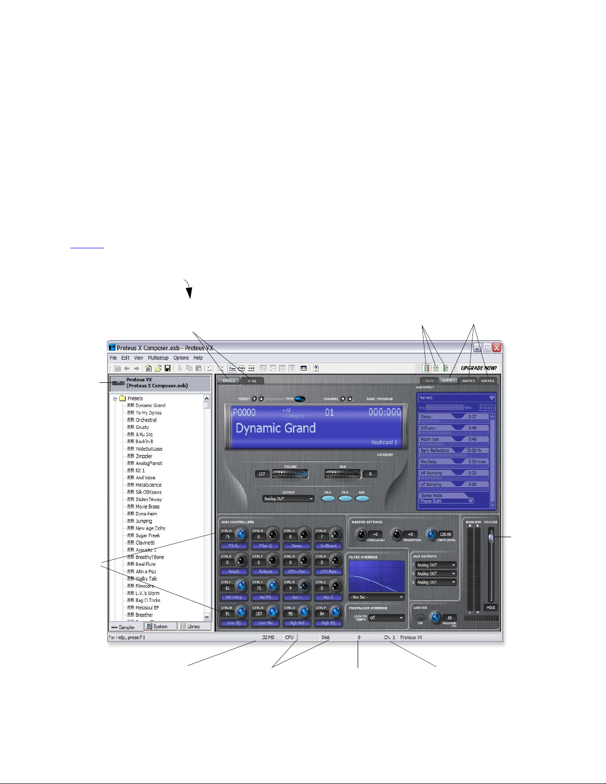
Click on the Proteus VX icon to display the Multisetup page.
There are two views in the Multisetup page. The Multisetup View buttons change the
current view. The Single channel view is shown below.
• Single................ Displays the preset for the currently selected MIDI channel.
• Channels 1-16.. Displays the preset, volume and pan for MIDI channels 1-16.
See page 37
for a complete description of the Multisetup screen.
Single Channel View
Single-Multi
Click
Here
View
Tabs
MIDI
Mode
Select
Aux FX
Display
Tab s
Master
Vol ume
MIDI
Controllers
Preroll
RAM Used
28 Proteus VX Operation Manual
CPU & Disk
Usage Meters
Samples
Playing
Current
Channel
Page 29
Changing Presets (from Single View)
Single View is the default view when you first run Proteus VX. This view is convenient
for performing live or when you’re only playing one preset at a time. All the main
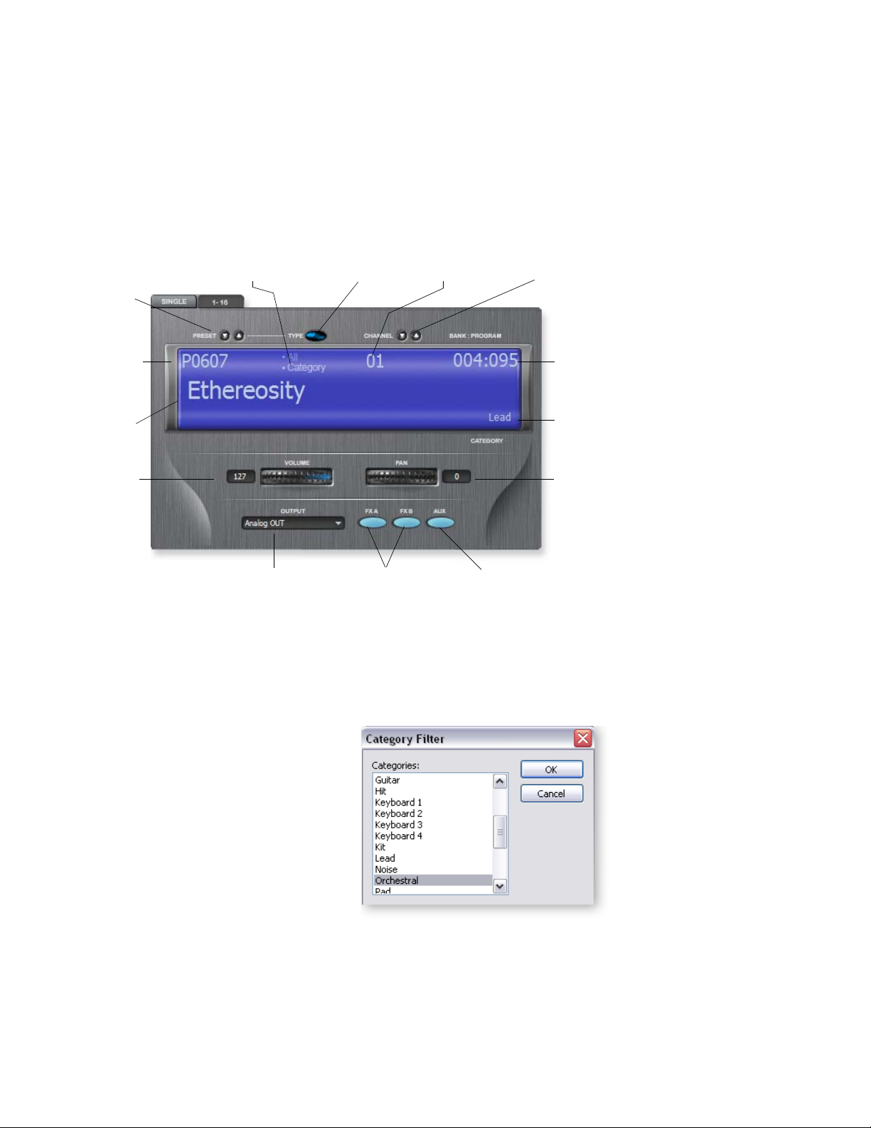
parameters for the selected MIDI channel are displayed in Single View and a convenient Category mode allows you to quickly select presets in a certain category. A closeup of the current channel settings is shown below.
Single View Close-up
2 - Guided Tours
Multisetup Page
Note that Single View
only changes the display
and does not affect the
currently selected MIDI
mode (i.e. Omni, Poly or
Multi).
Select All or Select
by Category
Preset
Inc/Dec
Select/View
Preset
Number
Preset
Name
Channel
Volume
Main Output
Select
To Select Presets by Number
Select
Category
FXA/FXB
Enables
Select/View
MIDI Channel
Aux Output
MIDI Channel
Inc/Dec
Bank/
Program
Display
Selected
Category
Channel
Pan
Enable
1. Click on the Preset Increment/Decrement buttons to move up or down the presets
by number.
2. Highlight the Preset Number field and type in the desired preset number.
The Bank/Program
Display shows the Bank
and Program number
you would use to select
the preset from a
sequencer.
To Select Presets by Category
1. Click on the Select Category button.
The pop-up dialog box at right appears.
2. Select the desired preset category, then
press OK.
3. Choose Select By Category from the
Single view screen above.
4. Use the Increment or Decrement
buttons to select presets. Note that only
presets of the selected category are
selected.
Changing the Current MIDI Channel
The Current MIDI Channel is simply the MIDI channel you are currently working with.
To change the current MIDI channel, simply increment or decrement the channel
number using the buttons, or click on the channel number and type in the desired
number.
E-MU Systems 29
Page 30
2 - Guided Tours
Multisetup Page
Channel 1-16 View
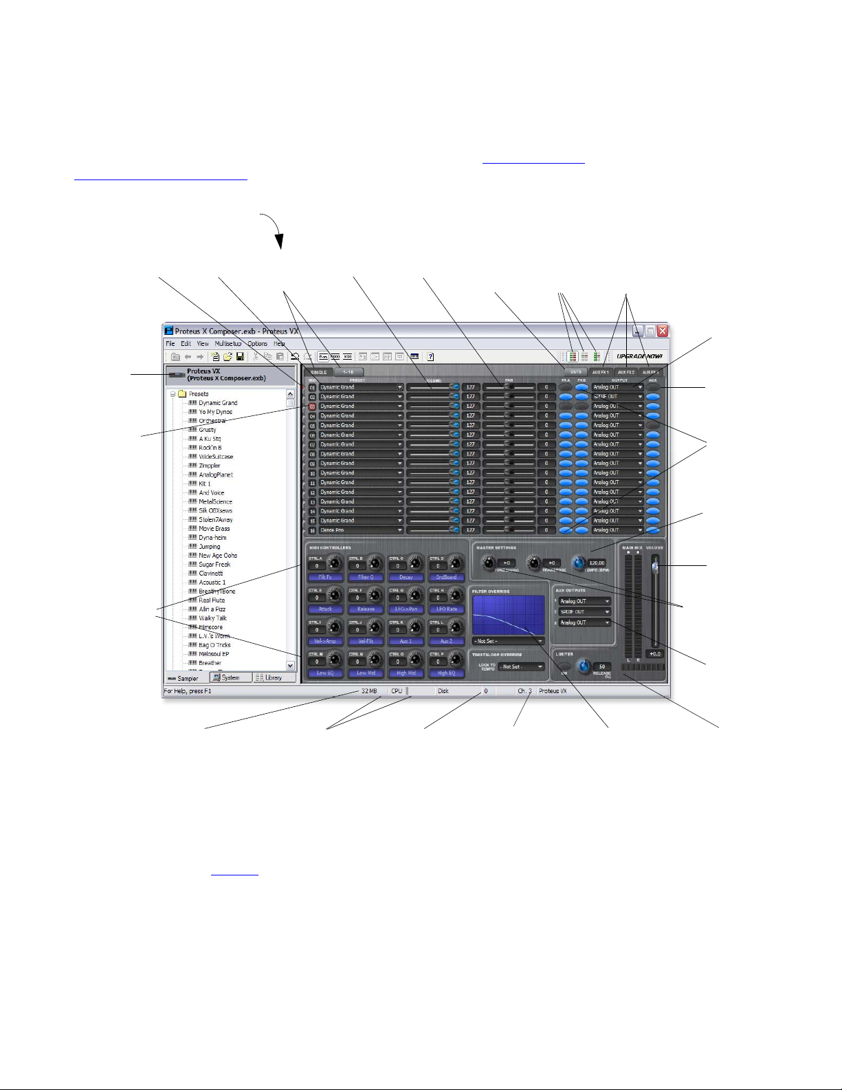
Press the Multisetup View 1-16 button to view channels 1-16 at the same time.
This page view is particularly useful when sequencing as you can see 16 MIDI channels
at once. Note that the Output Display button is now active. See also “
3 - Multisetup /
Global Controls” on page 37.
Channel 1-16 View
Click
Here
Current
Channel
Continuous
Controllers
MIDI
Activity
Preset
Select
Multisetup
View
Tab s
Channel
Volume
Channel
Pan
Output
Display
Tab
MIDI
Mode
Select
Aux FX
Display
Tabs
Main
Output
Routing
Aux Send
Enable
Preset FX
Enables
Master
Tempo
Master
Volume
Channel Tune
& Transpose
Aux
Output
Select
Preroll
RAM Used
CPU & Disk
Use Meters
Samples
Playing
Current
Channel
Filter
Override
Limiter
Changing Presets (from the 1-16 view)
Play your MIDI keyboard and note that one of the MIDI activity LEDs comes on. This is
the channel on which your MIDI keyboard is transmitting. If you don’t see MIDI
activity, check your MIDI connection and make sure MIDI is set up properly in the
Preferences menu. See page 20
To Audition and Select Presets
1. Click once on the Preset Select button on the channel used by your MIDI
keyboard. The complete list of all presets in the bank appears.
2. Click once on a preset to audition it. Play your keyboard to hear it.
3. Try out a few more presets. When you find one you like, double-click on it to select
it and return to the Multisetup screen.
30 Proteus VX Operation Manual
.
Page 31

2 - Guided Tours
Multisetup Page
4. Change the current channel by clicking on the number to the left of the preset. The
number you selected turns yellow.
5. Play the small keyboard at the bottom of the screen. Notice that the MIDI Activity
LED of the current preset now plays along with whatever sound is selected for that
channel. (Your MIDI keyboard still plays on the channel to which it is set.)
6. Change the channel on your MIDI keyboard then play it. The Proteus now plays
the preset on that channel.
Selecting Presets from the Tree
1. When you click on a preset in the tree, you have just selected it for the current MIDI
channel. This action also calls the Preset Global page.
2. To go back to the Multisetup page click the back arrow or click on the Proteus VX
icon at the top of the tree.
Changing the Current MIDI Channel
1. The Current MIDI Channel is simply the MIDI channel you are currently working
with.
2. To change the current MIDI channel, click on the channel number in the Multisetup page. The selected channel number turns yellow. Note also that the channel
number at the bottom of the window changes to reflect the current channel.
Selecting “None” in
the Preset field, disables
the MIDI Channel.
Adjusting the Controllers
Each preset has a set of 16 continuous controllers which are used to adjust and control
the sound as you play. Your MIDI keyboard may have several knobs or sliders that are
transmitted over MIDI. These can be used to control the Proteus VX if you match the
CC numbers your MIDI keyboard transmits to the same CC numbers on the Proteus
VX. These global settings are located under Options, Preferences, Controllers.
See page 22
See page 128
To Modify the Sound using the Controllers
1. Play your MIDI keyboard as you adjust the controller knobs on the screen. Notice
that the sound changes. If the sound doesn’t change, make sure the current preset
(red number) is the same one that your keyboard is playing.
2. If you have controller knobs on your MIDI keyboard and have set up the
Controllers (Options, Preferences, Controllers) to match your keyboard, you can
use these knobs to modify the sound. Notice that the on-screen knob follows the
movement of the hardware knob.
3. Try changing the filter type. Click on the selector to the right of the filter name and
select one of the 53 different filter types.
4. Adjust the Tone and Presence controls while playing the keyboard to hear your
changes.
5. Change the Volume and Pan controls for the MIDI channel you are using. These
settings can be adjusted remotely using MIDI controller #7 (volume) and
controller #10 (pan).
6. If you want to save the changes, you must set the Initial Controller Amounts in
the Preset Globals page to match the settings you made in the Multisetup page,
then save the bank.
and page 117 for additional information about MIDI controllers.
to see a chart of the Proteus VX MIDI controller functions.
E-MU Systems 31
Page 32
2 - Guided Tours
Create Your Own Custom Bank
Create Your Own Custom Bank
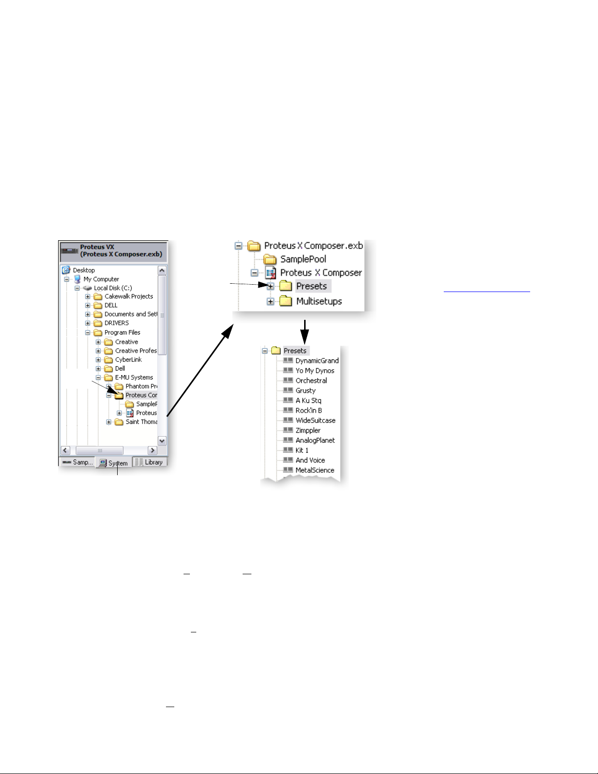
It’s easy to create your own custom sound banks by simply “dragging and dropping”
the presets you want onto the Proteus VX icon in the tree.
To Create a New Custom Bank
Locate the Presets on your Computer
1. Select New from the File menu. This creates a new empty bank. (You can also
merge presets into an existing bank if you wish.)
2. Select the System Tab. The Desktop icon will appear in the tree.
3. Locate the presets you wish to include in your new bank. These will be located in
the “Creative Professional” folder located in “Program Files”.
Click to
Open
Many other great
banks of sounds are
available from E-MU
Systems. Please visit our
web page at:
http://www.emu.com
Click to
Open
System Tab
Audition the Presets
4. After you have located the Presets folder, click on the Proteus VX icon in the Tree
to view the Multisetup page.
5. Find a preset in the Tree or List View and Right-click over it. A pop-up menu
appears with two options, A
6. Select Audition (or press “A” on your computer keyboard). Notice that the preset
name is now flashing in the Multisetup screen.
7. Play your MIDI keyboard to audition the preset from the hard disk.
8. Right-click again and select S
keyboard). The preset name stops flashing in the Multisetup screen.
9. Continue auditioning until you find a preset you like.
udition and Merge.
top Audition (or press “S” on your computer
Tip: You can als o
audition presets from the
library.
Merge the Preset
10. When you have found a preset you want to include, Right-click over it in the Tree
or List View and select M
erge from the menu (or press “M” on your computer
The List View allows
you to select multiple
presets to merge.
keyboard). The preset is added to the current bank.
32 Proteus VX Operation Manual
Page 33

Another Method of Merging Presets
11. Simply click (left mouse button) and drag the preset over the Proteus VX icon at
the top of the tree. The cursor changes to a plus sign as you pass over the icon.
Release the mouse button and a pop-up progress bar will inform you that the
preset is being loaded.
12. If you change your mind and don’t want to merge the preset after all, choose Undo
from the Edit menu to un-merge the preset.
Continue to Create the Bank
13. Continue to add presets to your new bank.
14. Save the bank when you are satisfied.
Alternate Method using the Librarian to find Presets
1. Select the Library Tab instead of the System Tab in step 3 above.
2. If you haven’t done so already, Update the Library.
3. Choose presets from the Library, then drag and drop them on top of the Proteus
VX icon at the top of the tree.
Save and Save As
When you choose “Save” or “Save As” from the file menu, the entire bank (except for
the samples) is re-written to the hard disk. Since presets don’t take up much memory,
this operation is fast.
Be sure to rename your bank when using Save As… to save an edited bank, otherwise
you may overwrite data you wanted to keep.
2 - Guided Tours
Create Your Own Custom Bank
Proteus VX Bank Structure
Banks are comprised of two distinct entities which need to be kept in the same folder
on your computer hard disk. The SamplePool contains the raw sample data used. The
Bank file contains all the voice, preset and multisample data that makes up the Proteus
VX bank.
E-MU Systems 33
Page 34
2 - Guided Tours
The Librarian
The Librarian
As your sound library grows so does the problem of managing all your banks and
presets. As you’ve probably already discovered, a single bank can contain literally
hundreds of presets.
The Library is accessed by clicking the Library tab at the bottom of the Tree. To use the
librarian, you first “Update” from the File menu. This creates a searchable database of
all your presets and banks which can be quickly searched.
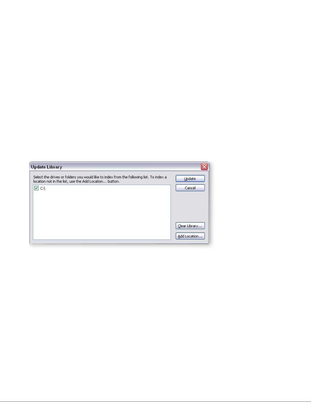
You can select which drives you wish to add to the catalog or manually “Add
Locations” to narrow down the selection range to speed the update process. The Add
Location button also allows you to specify network drives to catalog. Only the selected
targets are overwritten with new data when the update process is performed.
Unselected targets remain as they were. The “Clear Library” button erases the entire
library so you can start from scratch.
Using the Librarian
Catalog your Disks
1. Select Update from the File menu. A popup dialog box appears asking you to select
the disks you wish to catalog.
Update
Updates the Library with the selected items, leaving non-checked
targets intact.
Cool Tip: Categorize
multiple Presets:
1. Go to the Tree
2. Click the Presets folder.
3. Select multiple presets.
4. Right-click and choose
category.
5. Select category.
Clear Library
Add Location
Erases Library database.
Allows you to manually select targets to speed update time or select network
drives to catalog.
2. Select any disk drives that contain the banks and presets that were included when
you installed the Proteus VX application. Using the Add Location button, you can
select network drives to add to the Library catalog. The Add Location button also
allows you to select specific folders or locations for cataloging.
3. Click the Update button to begin cataloging. The display will read: “Updating”.
This process may take a few minutes depending on how many files need to be
cataloged.
34 Proteus VX Operation Manual
Page 35
Find your Files
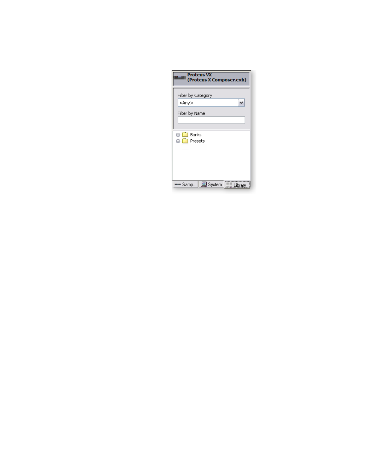
4. Select the Library tab at the bottom of the Tree. All Proteus VX Banks and Presets
can now be accessed here. This can take a few seconds, especially with large banks.
5. Click on the Presets folder to view all the
presets on your hard disks.
6. Select a Category of presets using the Filter by
Category option.
7. Browse through the Bank, and Preset folders to
find the sounds you want.
8. Right-click on a Preset to Audition the Preset
from disk. You must play the keyboard while
Auditioning to hear presets.
Load your Files
9. To add a file to the bank, Left-click and Drag
the desired object in the Library over the
Proteus VX icon at the top of the tree and
release the mouse button. The file is added to
the bank.
10. Or… Select the object you want from the
Library and Right-click. Then select Merge to merge the object into the current
bank.
2 - Guided Tours
The Librarian
Tip: You can add
Category tags to
your own presets by
Right-clicking on
them.
E-MU Systems 35
Page 36

2 - Guided Tours
The Librarian
36 Proteus VX Operation Manual
Page 37
3 - Multisetup / Global Controls
The Multisetup
The Multisetup is the top level of the Proteus VX hierarchy and is the place where you
choose and assign presets to each of the MIDI channels.
A multisetup assigns a preset, volume, pan position and output routing to each of the
16 MIDI channels. Multisetups can be saved and recalled for use with a particular song
or sequence so that all the MIDI channels play the proper preset.
To Select the Current Multisetup:
1. Click on the Proteus VX icon at the top of the Tree. The current multisetup
appears.
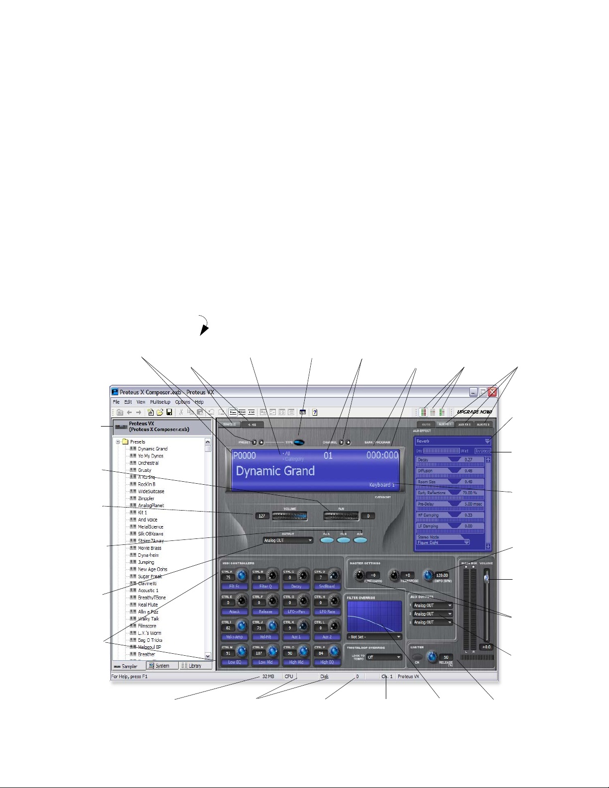
2. The Single Mode view is shown below. This view is convenient for performing live
or when you’re only playing one preset at a time.
Single Channel View
3 - Multisetup / Global Controls
The Multisetup
The MIDI Controller
settings and Filter
Override are not stored
with the Multisetup.
These settings are stored
with each Preset.
Click
Here
Channel
Pan
Channel
Volume
FXA, FXB,
Aux Output
Enables
Main
Output
Select
MIDI
Controllers
Preset
Select
Multisetup
View
Tabs
Select All or
by Category
Select
Category
Channel
Select
Bank &
Preset
Display
MIDI
Mode
Select
Aux FX
Display
Tabs
Select
Effect
Effect
Bypass
Preset
Category
Display
Master
Tempo
Master
Volume
Master
Tune &
Transpose
Aux
Output
Select
RAM Used CPU & Disk
Usage Meters
E-MU Systems 37
Samples
Playing
Current
Channel
Filter
Override
Limiter
Page 38
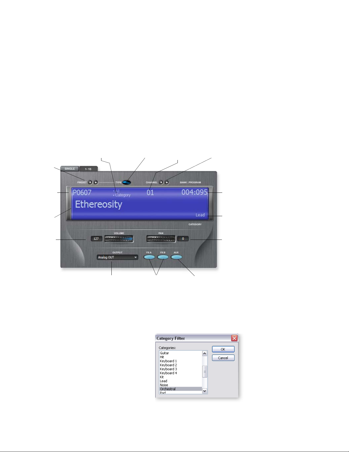
3 - Multisetup / Global Controls
The Multisetup
There are two views in the Multisetup page. The Multisetup View buttons change the
current view.
• Single................ Displays the preset for the currently selected MIDI channel.
• Channels 1-16.. Displays the preset, volume and pan for MIDI channels 1-16.
Changing Presets (from Single View)
Single View is the default view when you first run Proteus VX. This view is convenient
for performing live or when you’re only playing one preset at a time. All the main
parameters for the selected MIDI channel are displayed in Single View and a convenient Category mode allows you to quickly select presets in a certain category. A closeup of the current channel settings is shown below.
Single View Close-up
Note that Single View
only changes the display
and does not affect the
currently selected MIDI
mode (i.e. Omni, Poly or
Multi).
Select All or Select
by Category
Preset
Inc/Dec
Select/View
Preset
Number
Preset
Name
Channel
Volume
Main Output
Select
To Select Presets by Number
Select
Category
FXA/FXB
Enables
Select/View
MIDI Channel
Aux Output
Enable
MIDI Channel
Inc/Dec
Bank/
Program
Display
Selected
Category
Channel
Pan
1. Click on the Preset Increment/Decrement buttons to move up or down the presets
by number.
2. Highlight the Preset Number field and type in the desired preset number.
To Select Presets by Category
1. Click on the Select Category button. The
pop-up dialog box at right appears.
2. Select the desired preset category, then
press OK.
3. Choose Select By Category from the Single
view screen above.
4. Use the Increment or Decrement buttons
to select presets. Note that only presets of
the selected category are selected.
The Bank/Program
Display shows the Bank
and Program number
you would use to select
the preset from a
sequencer.
You can also use the
up/down arrow keys on
your computer keyboard
to inc/dec presets when
the preset number field
has the cursor.
38 Proteus VX Operation Manual
Page 39
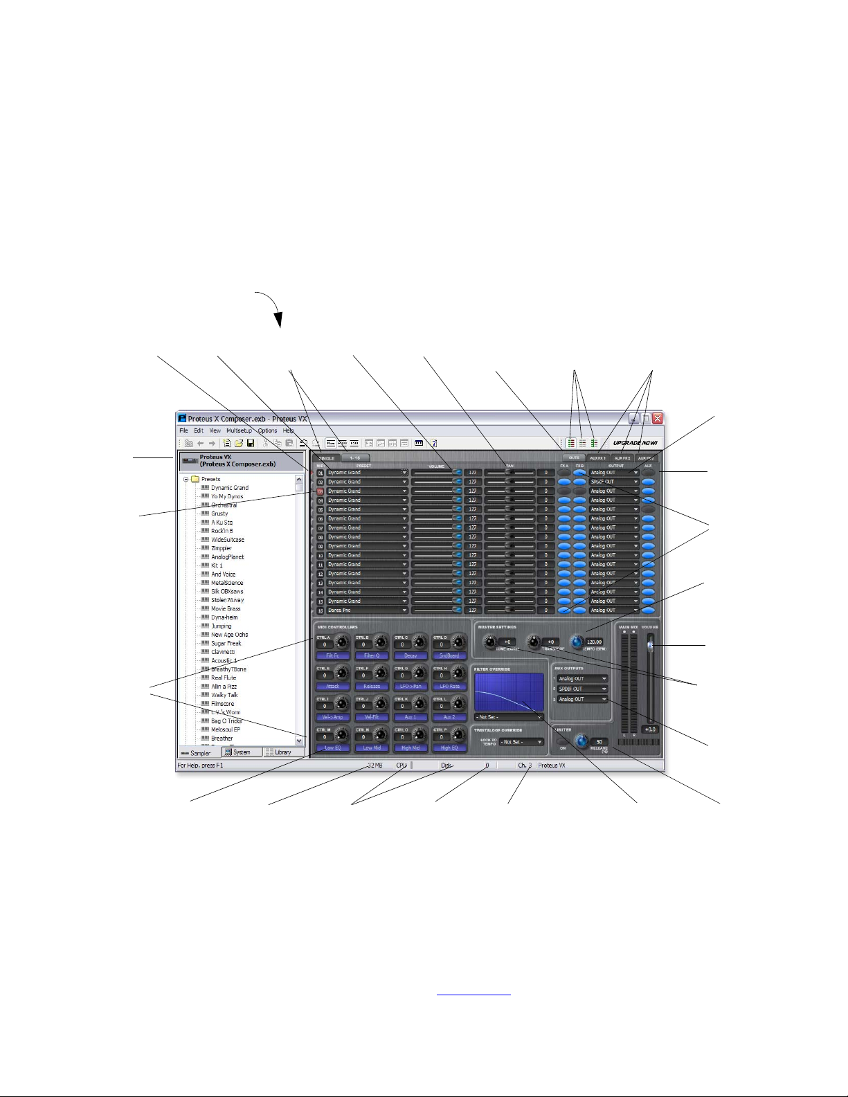
Changing the Current MIDI Channel
The Current MIDI Channel is simply the MIDI channel you are currently working
with. To change the current MIDI channel, simply increment or decrement the
channel number using the buttons, or click on the channel number and type in
the desired number.
16 Channel View
Press the 1-16 Multisetup View button to view 16 channels at once. This mode is useful
for sequencing or when playing multiple MIDI channels.
Channel 1-16 View
3 - Multisetup / Global Controls
The Multisetup
Click
Here
Current
Channel
MIDI
Controllers
MIDI
Activity
Preset
Select
Single-Multi
View
Tabs
Channel
Volume
Channel
Pan
Output
Display
Tab
MIDI
Mode
Select
Aux FX
Display
Tabs
Main
Output
Routing
Aux Send
Enables
Preset FX
Enables
Master
Tempo
Master
Volume
Master Tune
& Transpose
Aux
Output
Select
Definable
Labels
Preroll
RAM Used
CPU & Disk
Use Meters
No. of
Samples
Playing
Current
Channel
Filter
Override
Limiter
Saving your Multisetup
The current Multisetup is automatically saved when you save your Project in the
recording application (Cubase, Sonar, etc.).
• Simply set up the Multisetup the way you want it, or select one from the Tree or List
View, then Save your project. The Multisetup will be saved along with your song.
• You can also save multisetups with the bank of sounds. See page 48.
E-MU Systems 39
Page 40

3 - Multisetup / Global Controls
The Multisetup
The Current MIDI Channel
Change the current channel by clicking anywhere on the desired horizontal channel
strip. The yellow indicator displays the currently selected channel number. The MIDI
Controllers change to show the settings of the currently selected MIDI channel.
To Select a Preset:
1. Click on the Preset Select button for the desired MIDI channel. The Select Preset
dialog box appears.
2. Click on the presets in the list to audition them. Presets can be viewed by large
icon, small icon, by list, or by detailed list. Presets can also be sorted by name, ID,
bank/program number, or category when in Detail View mode.
3. To choose a preset, select it and press OK, or double-click on the preset in the list.
To Select a Preset from the Tree or List View:
1. Set the Current Channel by clicking anywhere on a horizontal channel strip in the
Multisetup window.The channel number turns yellow, indicating that this is the
current channel.
2. Choose the preset you want in the tree or list view and Right-Click on its preset
icon.
3. Choose Select on Current Channel. The preset is now selected for that channel.
4. You can also select a preset for the current channel by simply clicking the preset’s
keyboard icon from the tree or list view.
MIDI Channel
Each channel only responds to MIDI data on its particular channel. Use the small
keyboard at the bottom of the window to audition presets on the currently selected
channel. Select the current channel by clicking anywhere on the desired channel strip.
The yellow indicator displays the currently selected channel number.
Preset Assignment
Assign presets to MIDI channels by clicking on the selector button to the right of the
preset field. A pop-up dialog box appears with the list of presets in the bank. Select a
preset, then click OK to select.
Channel Volume
This control sets the relative volume of the MIDI channel. This is equivalent to MIDI
controller #7 (channel volume) and changes made over MIDI will be shown here.
Channel Pan
This control sets the stereo position of the MIDI channel. This is equivalent to MIDI
controller #10 (channel pan) and changes made over MIDI will be shown here.
Output Assignment
This control selects the Main Output assignment for the MIDI
channel. 100% of the stereo output signal is sent to the selected
output bus.
The number of outputs available in this field depends on the number of stereo
channels you have allocated. By default, you’ll only have Bus 1.
• Add VST Output Buses in the Proteus VX Preferences to increase the number of
available outputs.
40 Proteus VX Operation Manual
Page 41
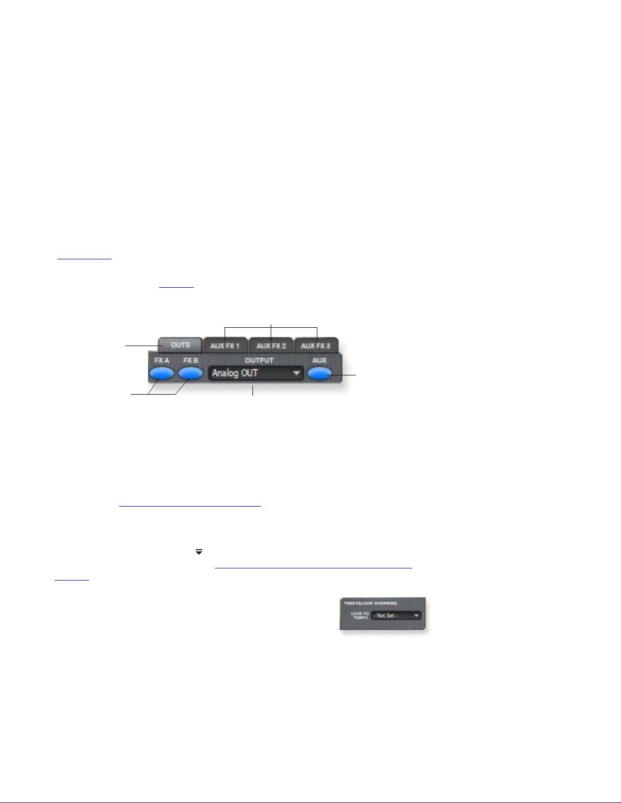
Output View Button
This button allows you to view the Aux Send On/Off, Main Output Routing, and Preset
FXA/FXB Bypass buttons when not in Single Mode. (The button is disabled in Single
mode.)
You may want to bypass the Preset Effects on certain channels in order to free up CPU
power or to hear the presets dry.
Aux FX View Buttons
The buttons above the TV display select which of the three possible Aux Effect is
currently displayed. Note: The Output View button is disabled in Single mode.
Aux Send On/Off
These buttons enable (blue) or disable (grey) the inputs to the Aux Sends for each
MIDI channel. These buttons also enable/disable the Aux Outputs for each channel.
See page 43.
These buttons disable the Aux Sends whether the Aux FX are being used or not. Please
refer to the diagram on page 62
path.
The Main Output is unaffected by these buttons.
to see the exact location of this switch in the signal
Aux Effect View Buttons
3 - Multisetup / Global Controls
The Multisetup
The Output View
button is only available
when the 1-16 view is
selected. In Single mode
you can only control the
current channel.
Output View
Button
Aux Send
Preset FX
Enable Buttons
Main Output
Routing
On/Off
Preset FX Enables
These two rows of buttons marked FXA and FXB, enable or disable the preset effects for
each MIDI channel. These work differently than the Aux Send On/Off buttons in that
they bypass the effects instead of turning them on or off. These buttons are useful to
bypass any preset effects which may have been programmed in the preset.
Please refer to Chapter “5 - Effects” on page 59
for detailed information about the
output and effects routing.
Select Effect
Click on the Effect Select icon at the top right corner of the Effects TV screen. A list
of available effects drops down. See “Adding an Aux Effect in the Multisetup” on
page 60 for complete details on how to add aux effects.
TwistaLoop Override
This three-way switch determines if the beat looping features
are locked to Master Tempo. The three modes are as follows:
• On: . . . . . . Beats on the channel are locked to the Global
Master Tempo. This control overrides the “Sync To Master Clock”
setting in the preset.
• Off: . . . . . Beats on the channel are NOT locked to the Global Master Tempo. This
control overrides the “Sync To Master Clock” setting in the preset.
• Not Set: . . The “Sync To Master Clock” button in the Preset Globals page determines whether or not the Beats are locked to the Global Master Tempo.
E-MU Systems 41
Page 42
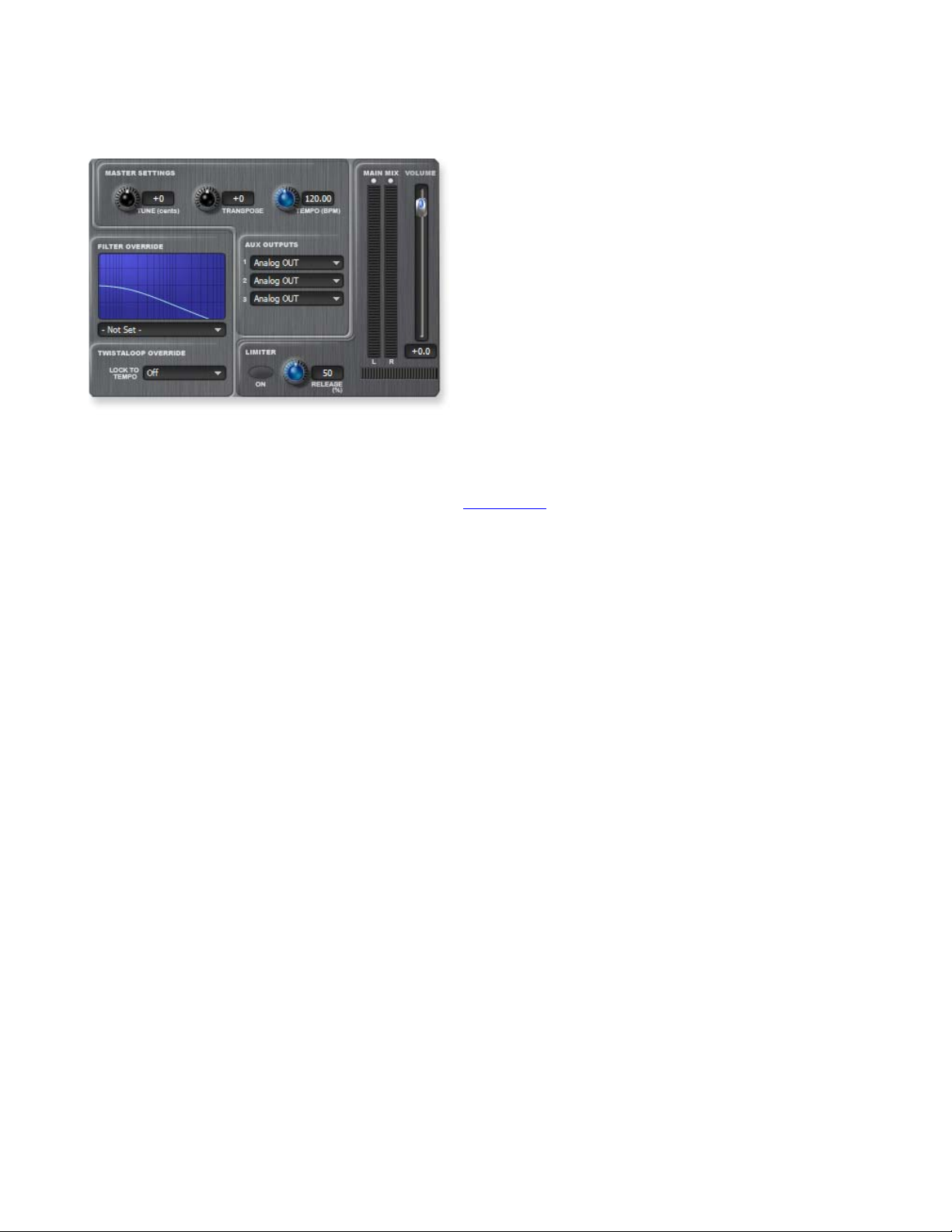
3 - Multisetup / Global Controls
Global Controls
Global Controls
Master Volume Control & VU Meter
This is the master volume control for the Proteus VX. This slider controls the output
volume of all MIDI channels.The range of this control can be adjusted using the
Headroom/Boost control in the Preferences dialog box. See page 20.
The VU meter indicates the overall output level of the Proteus VX Main Outputs. It
serves as a handy indicator to show clipping or to troubleshoot audio output
problems.
Tempo Cont ro l
This control and associated display sets the master tempo when the Proteus is chosen
as the tempo source. Proteus VX contains a global master clock which is used for
Tempo-based Envelopes, the Twistaloop features, Tempo-based LFOs, and clock
modulation.
IMPORTANT: “External Tempo Source” in the MIDI Preferences dialog must be OFF
for this control to operate.
When “External Tempo Source” in the preferences dialog box is On, and an external
MIDI device or application is generating MIDI clock, the Proteus VX tempo will lock to
the MIDI clock tempo.
Master Tune
Master Tune adjusts the overall tuning of all presets so you can tune Proteus VX to
other instruments. The master tuning range is ±1 semitone in one cent steps (1/100th
of a semitone). A master tune setting of 0¢ indicates that the Proteus VX is precisely
tuned to concert pitch (A=440 Hz).
Master Transpose
The master transpose parameter transposes the key of all presets in semitone intervals.
The transpose range is ±12 semitones (1 octave).
Limiter
When playing the Proteus VX you may sometimes hear digital clipping. This clipping
occurs in the digital hardware and is not caused by the Proteus VX, which uses high
resolution floating point processing and has tremendous internal headroom.
To avoid the clipping, you could always lower the volume controls, but there’s a better
way. The Limiter monitors the signal ahead of the output stage and automatically turns
down the volume before clipping can occur.
42 Proteus VX Operation Manual
Page 43
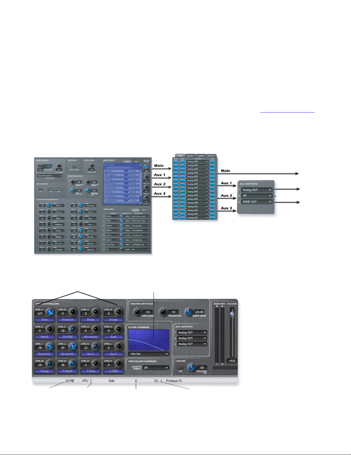
To Use the Limiter
1. Press the Enable button, illuminating the button.
2. Set the Release knob to about 30% to start. Release controls how fast the limiter
turns the volume back up after reducing it to avoid the clipping peaks.
3. Increase the release time if you hear obvious volume changes (pumping). Reduce
the release time for percussive playing.
Aux Outputs
These three output assignments assign the Aux Sends to buses going to the Host application. The Aux Output Assignment section of the Multisetup allows you to assign each
of the three Aux Sends to a separate Bus to the Host Application if you so desire.
Important: You must select the number of available buses in the Proteus VX
Preferences menu before they become available.
Proteus VX Aux Bus Routing
3 - Multisetup / Global Controls
Global Controls
See Chapter
“5 - Effects” on page 59
for complete descriptions
of the effects routing.
Main Out
Main Out
PRESET
IDI real-time Controllers & Scribble Strips
Off
S/PDIF Out
Aux Out
Assignment
MULTI
(only visible in 1-16 view)
Filter Override
Preroll RAM CPU Meter Number of Samples Current Channel
E-MU Systems 43
Page 44
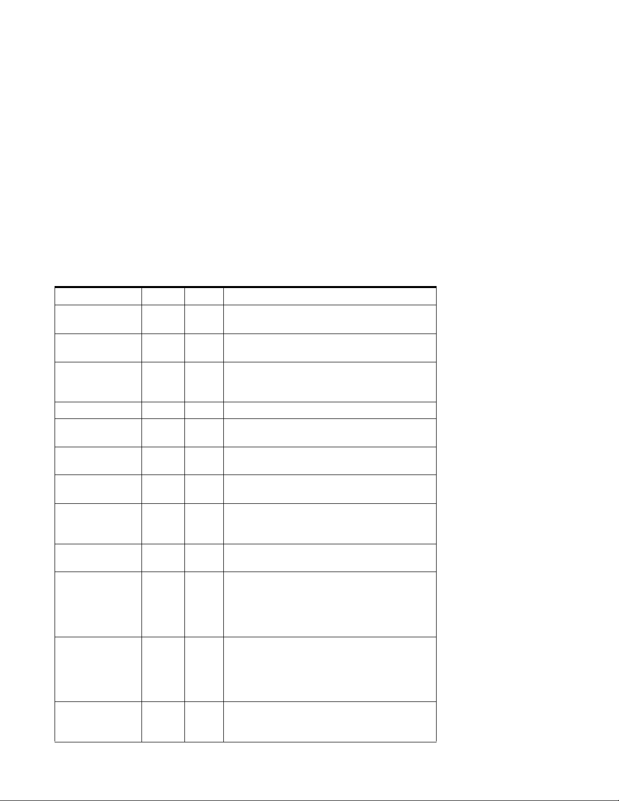
3 - Multisetup / Global Controls
Global Controls
Filter Override
The filter type of the first voice in the preset (on the currently selected channel) is
shown in this display. If you change the filter type in this field, ALL the voices in the
preset will change to the filter type you select. When the display reads, - Not Set - the
filters programmed in each voice will be used. The filters may be set differently for each
voice.
You can choose from 55 different filter types or choose “No Filter”, which bypasses the
filter section.
The frequency response curve of the filter is accurately shown in the display.
Frequency is shown on the horizontal axis, with amplitude on the vertical axis.
You will notice an increase in voice count when the filters are bypassed as the filters
steal cycles from your computer’s CPU. 12th order filters use more CPU and therefore
decrease the maximum voice count.
Filter Descriptions
Filter Name Order Type Description
2-pole Lowpass 02 LPF Typical OB type low-pass filter with a shallow
12 dB/octave slope.
4-pole Lowpass 04 LPF 4-pole low-pass filter, the standard filter on
classic analog synths. 24 dB/octave rolloff.
6-pole Lowpass 06 LPF 6-pole low-pass filter which has a steeper
slope than a 4-pole low-pass filter. 36 dB/
octave rolloff!
2-pole Highpass 02 HPF 2-pole high-pass filter. 12 dB/octave slope.
4-pole
Highpass
2-pole
Bandpass
4-pole
Bandpass
Contrary
Band pass
SweptEQ
1 octave
Swept EQ
2->1 octave
Swept EQ
3->1octave
Phaser 1 06 PHA Recreates a comb filter effect typical of phase
04 HPF Classic 4-pole high-pass filter. Cutoff sweep
progressively cuts 4th Order High-pass.
02 BPF Band-pass filter with 6 dB/octave rolloff on
either side of the passband and Q control.
04 BPF Band-pass filter with 12 dB/octave rolloff on
either side of the passband and Q control.
06 BPF A novel band-pass filter where the frequency
peaks and dips midway in the frequency
range.
06 EQ+ Parametric filter with 24 dB of boost or cut
and a one octave bandwidth.
06 EQ+ Parametric filter with 24 dB of boost or cut.
The bandwidth of the filter is two octaves
wide at the low end of the audio spectrum,
gradually changing to one octave wide at the
upper end.
06 EQ+ Parametric filter with 24 dB of boost or cut.
The bandwidth of the filter is three octaves
wide at the low end of the audio spectrum,
gradually changing to one octave wide at the
upper end.
shifters. Frequency moves position of notches.
Q varies the depth of the notches.
Filter Types
BPF Band-pass filter
EQ+ EQ boost filter
EQ- EQ cut filter
FLG Flanger filter
HPF High-pass filter
LPF Low-pass filter
PHA Phaser filter
PROG Programmable
REZ Highly Resonant
SFX Special Effect
VOW Vow el / form ant
WOW Wah-Wah pedal
44 Proteus VX Operation Manual
Page 45
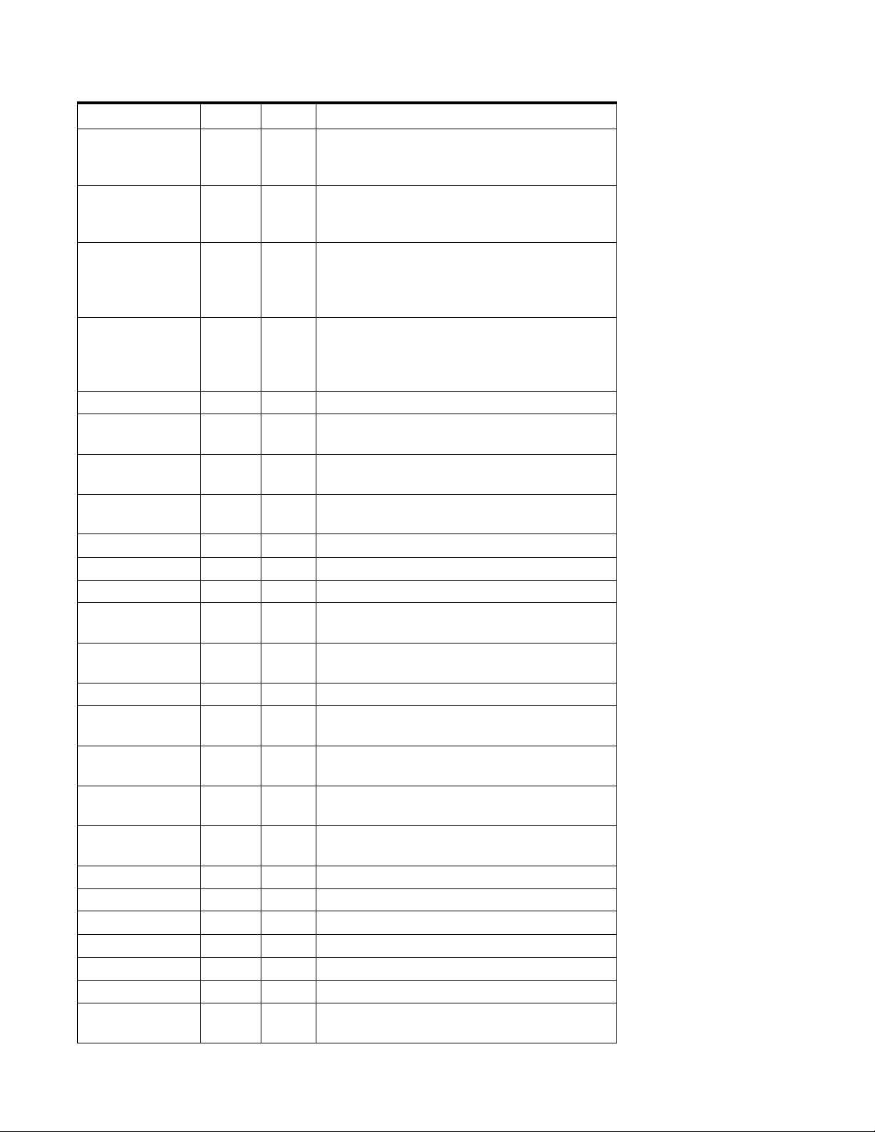
Filter Name Order Type Description
Phaser 2 06 PHA Comb filter with slightly different notch
frequency moving the frequency of notches.
Q varies the depth of the notches.
FlangerLite 06 FLG Contains three notches. Frequency moves
frequency and spacing of notches.
Q increases flanging depth.
Vocal
Aah-Ay-Eeh
06 VOW Vowel formant filter which sweeps from “Ah”
sound, through “Ay” sound to “Ee” sound at
maximum frequency setting. Q varies the
apparent size of the mouth cavity.
Vocal Ooh-Aah 06 VOW Vowel formant filter which sweeps from “Oo”
sound, through “Oh” sound to “Ah” sound at
maximum frequency setting. Q varies the
apparent size of mouth cavity.
Dual EQ Morph 06 PROG As programmed in the Voice
Dual EQ +
06 PROG As programmed in the Voice
Lowpass Morph
Dual EQ Morph
06 PROG As programmed in the Voice
+ Expression
Peak/Shelf
06 PROG As programmed in the Voice
Morph
Morph Designer 2 - 12 PROG As programmed in the Voice
Ace of Bass 12 EQ+ Bass-boost to bass-cut morph
MegaSweepz 12 LPF “Loud” LPF with a hard Q. Tweeters beware!
EarlyRizer 12 LPF Classic analog sweeping with hot Q and
Low-end.
Millennium 12 LPF Aggressive low-pass filter. Q gives you a variety
of spiky tonal peaks.
MeatyGizmo 12 REZ Filter inverts at mid-Q.
KlubKlassik 12 LPF Responsive low-pass filter sweep with a wide
spectrum of Q sounds
BassBox-303 12 LPF Pumped up lows with TB-like squelchy Q
factor.
FuzziFace 12 DST Nasty clipped distortion. Q functions as
mid-frequency tone control.
DeadRinger 12 REZ Permanent “Ringy” Q response.
Many Q variations.
TB-OrNot-TB 12 EQ+ Great Bassline “Processor.”
Ooh-To-Eee 12 VOW Oooh to Eeee formant morph.
BolandBass 12 EQ+ Constant bass boost with mid-tone Q control.
MultiQVox 12 VOW Multi-Formant, Map Q To velocity.
TalkingHedz 12 VOW “Oui” morphing filter. Q adds peaks.
ZoomPeaks 12 REZ High resonance nasal filter.
DJAlkaline 12 EQ+ Band accentuating filter, Q shifts “ring”
frequency.
3 - Multisetup / Global Controls
Global Controls
E-MU Systems 45
Page 46

3 - Multisetup / Global Controls
Global Controls
Filter Name Order Type Description
BassTracer 12 EQ+ Low Q boosts bass. Try sawtooth or square
waveform with Q set to 115.
RogueHertz 12 EQ+ Bass with mid-range boost and smooth Q.
Sweep cutoff with Q at 127.
RazorBlades 12 EQ- Cuts a series of frequency bands.
Q selects different bands.
RadioCraze 12 EQ- Band limited for a cheap radio-like EQ
Eeh-To-Aah 12 VOW “E” to “Ah” formant movement. Q accentuates
“peakiness.”
UbuOrator 12 VOW Aah-Uuh vowel with no Q. Raise Q for throaty
vocals.
DeepBouche 12 VOW French vowels! “Ou-Est” vowel at low Q.
FreakShifta 12 PHA Phasey movement. Try major 6 interval and
maximum Q.
CruzPusher 12 PHA Accentuates harmonics at high Q. Try it with a
sawtooth LFO.
AngelzHairz 12 FLG Smooth sweep flanger. Good with vox waves.
e.g. I094, Q =60
DreamWeava 12 FLG Directional Flanger. Poles shift down at low Q
and up at high Q.
AcidRavage 12 REZ Great analog Q response. Wide tonal range.
Try it with a sawtooth LFO.
BassOMatic 12 REZ Low boost for basslines. Q goes to distortion
at the maximum level.
LucifersQ 12 REZ Violent mid Q filter! Take care with Q values
40-90.
ToothComb 12 REZ Highly resonant harmonic peaks shift in
unison. Try mid Q.
EarBender 12 WAH Midway between wah & vowel. Strong
mid-boost. Nasty at high Q settings.
KlangKling 12 SFX Ringing Flange filter. Q “tunes” the ring
frequency.
MIDI Controllers & Scribble Strips
Sixteen real-time MIDI Controllers are available to control the preset on the currently
selected channel. These controllers are connected to MIDI sources as assigned in the
Preferences dialog box (page 22
) and changes made over MIDI will be reflected here.
The scribble strip names and the initial settings of the controller knobs are user
programmable in the Preset Globals window. See page 52
.
Preroll RAM Used
This display shows how much of your computer’s RAM is being used by pre-roll sound
data (samples). See page 18
46 Proteus VX Operation Manual
.
Page 47

CPU Meter
This display shows how much of your computer’s CPU power is being used by the
Proteus VX.
Number of Samples Playing
This display shows you how many samples are currently being played. The maximum
number of samples that can be played depends on a variety of factors such as: HD
speed, RAM memory speed and CPU speed. See “Audio Setup” on page 19
information about performance.
for more
Current Channel
This displays the currently selected MIDI channel. Change the current channel by
clicking anywhere on the desired channel strip.
3 - Multisetup / Global Controls
Global Controls
E-MU Systems 47
Page 48

3 - Multisetup / Global Controls
Working with Multisetups
Working with Multisetups
A Multisetup is a “snapshot” of the current Proteus VX settings. Multisetups store the
preset, volume, pan position, and output bus routings for 16 MIDI channels along with
the Global Tempo and the three Aux Send destinations.
Saving FX & Multisetups
It is important to realize what data is stored in a multisetup when saving banks. In
addition to Volume, Pan, and Preset choices for each channel, the FX Aux 1, Aux 2, and
Aux 3 are stored with the multisetup. The send level for each preset to each Aux bus is
stored in the preset data. Remember to save the bank whenever you have made
changes that you want to keep.
VSTi Multisetups
A multisetup for your VSTi is stored in your Cubase project and will be loaded when
the project is opened. This multisetup overrides whatever default multisetup may have
been saved if the bank was opened in Proteus VX standalone mode. If you wish to store
extra multisetups you may do by using the Multisetup menu on the toolbar.
To Save the Current Multisetup
1. Set up all the multisetup parameters the way you want them.
2. Select Save from the Multisetup window on the toolbar.
3. Choose a name and number for the multisetup. Changing the number allows you
to place the Multisetup anywhere you want in the list.
4. Press OK to save the Multisetup.
5. Save the Bank, otherwise nothing will be saved.
To Restore a Multisetup
1. Open the multisetup folder in the Tree. Any multisetups contained in the bank will
be listed below the folder.
2. Left-click on the desired multisetup icon in the Tree or and drag it over the
Proteus VX icon above the Tree. This multisetup will be restored.
3. Alternate Method - Right-click over the Multisetup icon in the Tree and choose
Load.
To Export the Multisetup as a New Bank
This feature lets you save only the presets and samples you need as a new bank.
1. Set up all the multisetup parameters the way you want them.
2. Select Export from the Multisetup window on the toolbar. The popup “Save As”
dialog box appears prompting you for the save location.
3. Choose the location for your new bank and click Save to save the bank, or click
Cancel to cancel the operation.
To Rename a Multisetup
1. Open the multisetup folder in the Tree. Any multisetups contained in the bank will
be listed below the folder.
2. Right-click on the desired multisetup icon in the Tree (or list view), then select
Rename from the pop-up menu.
3. Type in a new name for the multisetup.
48 Proteus VX Operation Manual
Page 49

To Delete a Multisetup
1. Open the multisetup folder in the Tree. Any multisetups contained in the bank will
be listed below the folder.
2. Right-click on the desired multisetup icon in the Tree (or list view), then select
Delete from the pop-up menu.
3. The Multisetup will be deleted.
To Duplicate a Multisetup
1. Open the multisetup folder in the Tree. Any multisetups contained in the bank will
be listed below the folder.
2. Right-click on the desired multisetup icon in the tree, then select Duplicate from
the pop-up menu.
3. The Multisetup will be duplicated renamed “Copy of…XX” and placed in the first
empty Multisetup location.
To Rearrange the Order of Multisetups
1. Click once on the multisetup folder in the tree. The list of multisetups appears.
2. Select Details View from the view options in the toolbar and change the ID
number.
3. If you try to save a Multisetup with a number that is already used, a popup dialog
box will appear asking you if you want to use the next available ID number or
enter a new ID.
3 - Multisetup / Global Controls
Working with Multisetups
E-MU Systems 49
Page 50

3 - Multisetup / Global Controls
Working with Multisetups
50 Proteus VX Operation Manual
Page 51
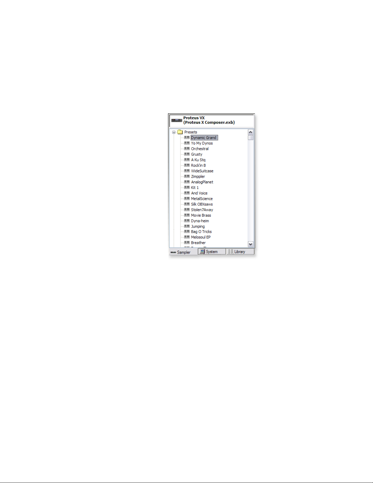
4 - Preset Editor
The Preset Editor allows you to edit the tuning, keyboard tuning table, initial controller
amounts, preset level effects and the preset patchcords.
All the Preset Editor parameters are saved when you save the bank.
To Select a Preset for Editing:
1. Choose the preset you want in the tree and
Left-Click on its preset icon.
2. The Preset Editor page appears
Alternate Selection Method:
1. Simply double-click on the preset name in
the Multisetup View (either in Single or Multi
view).
To Edit a Preset:
1. Adjust the Initial Controller Amounts and
note their effect on the sound. These are the
main synthesizer control parameters and can
produce dramatic changes in the sound.
4 - Preset Editor
Controllers K & L are normally used to control the global effects amounts.
Controllers M-P are usually connected to
various controls on the Preset FX.
2. Next try changing the Preset FX and the parameters associated with each effect.
3. The Preset Cords can also be edited. These cords are quite useful for controlling
the Preset FX via MIDI controllers. The available FX parameters depend on which
Preset FX you have selected.
4. The Volume, Transpose and the Tuning Table can be edited and saved. Try out
some of the different tuning tables.
•The Poly Timer and Channel Ramp are NOT used in any of the Proteus VX
Composer presets and so these controls have no effect on the sound.
•The Channel Lags are used on several of the organ presets. Look at the Preset Cord
routings to find out which ones.
Adding Preset Effects
uses CPU cycles. If a
preset is used by multiple
MIDI channels and you
add Preset FX, the CPU
penalty is multiplied for
each channel that uses
the preset.
E-MU Systems 51
Page 52
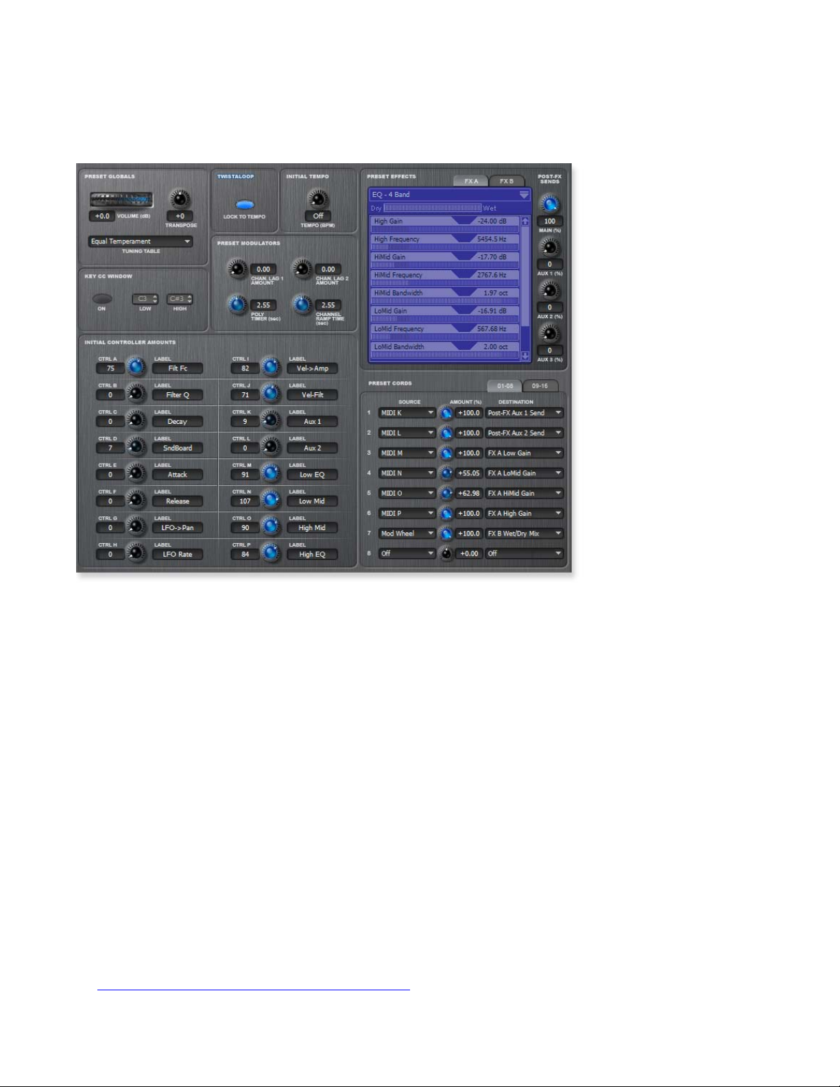
4 - Preset Editor
Preset Globals
Preset Globals
These parameters affect the entire preset and are saved with the bank.
Transpose & Volume
Transpose works by shifting the keyboard position. The actual samples are not retuned.
In other words, if you have the same sound on each key, such as a piano, the piano will
change key when you transpose. On the other hand, if you have a different drum
assigned to each key, changing transpose will shift the position of the drums on the
keyboard.
The volume control allows you to adjust the volume for the entire preset. This control
is variable from -96 dB (off) to +10 dB.
Initial Controllers A-P
These set the initial value of MIDI controllers A-P for the preset. As soon as a MIDI
controller is moved, it jumps immediately from this initial setting to the new setting of
the control. The controllers A-P are assigned to MIDI continuous controller numbers in
the Preferences dialog box.
Controllers A-P can be adjusted via MIDI or by turning the controller knob in the
Multisetup.
The Label fields to the left of the initial controller knobs are user definable. These labels
or “Scribble Strips” also appear in the Multisetup screen to show the function of the
real-time controller knobs.
MIDI Channels & Real-time Controls” on page 117 for additional information
See “
about Controllers A-P.
Changing the initial
controller settings is an
easy way to customize a
preset. Simply change the
knobs and save the bank.
52 Proteus VX Operation Manual
Page 53
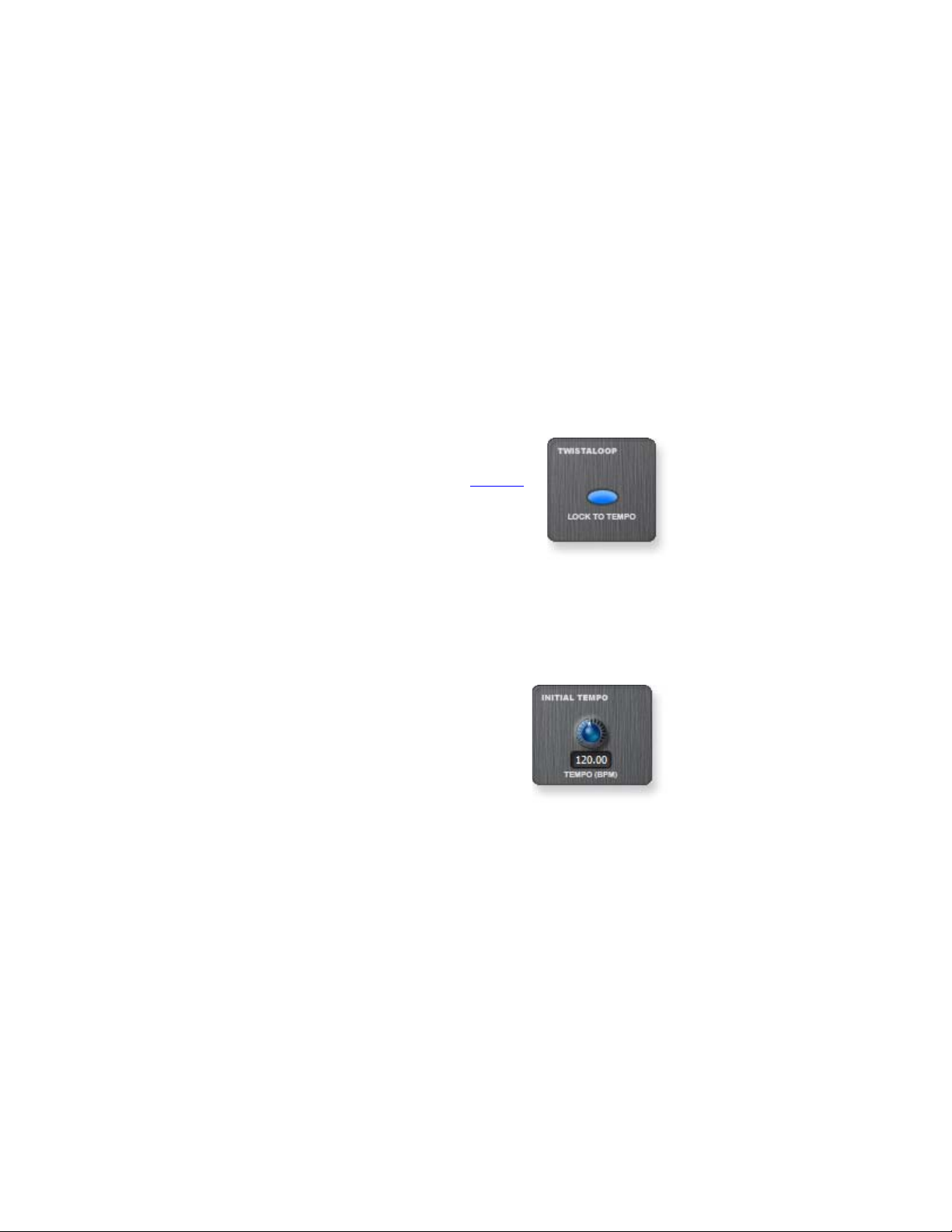
Capture MIDI Controllers
You can capture the state of all your MIDI input device’s MIDI controllers, and place
the settings in the Initial Controllers section of the Preset. Essentially, this allows you to
capture the Multisetup’s MIDI controller state, and store it in the preset.
To Capture MIDI Controllers
1. Make any desired changes to any MIDI controllers on your MIDI input device, or
in the Multisetup window.
2. Go to the Preset Globals window for the preset you want to apply your current
MIDI state.
3. From the Preset menu, select Capture MIDI Controllers.
4. Notice that the initial controllers now reflect the state of your MIDI controllers. To
keep these settings, you can save the Preset.
TwistaLoop Lock To Tempo
This control locks all analyzed beats in the preset to the global
master tempo. When this function is on, all beats in the preset will
lock to the master tempo unless “TwistaLoop Override” (page 41
is turned off.
)
4 - Preset Editor
Preset Globals
This button works in combination with “TwistaLoop Override.”
When TwistaLoop Override is “Not Set,” this button determines
whether beats sync to the master tempo for the preset. When TwistaLoop Override is set to On or Off for the MIDI channel, this button has no effect.
These two controls allow you to set the state of “Sync to Master Clock” by MIDI
channel (TwistaLoop Override) or by Preset (this button).
Initial Tempo
This feature allows the master tempo to be programmed from
presets that use tempo-based envelopes, LFOs or TwistaLoop.
The Initial Tempo works in combination with the “Preset Tempo
Channel” option in the Preferences menu, which allows one
specific MIDI channel to control the master tempo.
When the Initial Tempo is set to a tempo on the defined Preset
Tempo Channel, the master tempo will follow this tempo
setting when the preset is selected.
To Set the Master Tempo from a Preset:
1. Turn Preset Tempo Channel on and set it to the desired MIDI control channel.
(Options, Preferences, MIDI) “External Tempo Source” must be turned off.
2. Set the Initial Tempo (Preset Globals) to the desired tempo.
3. Turn on TwistaLoop - Lock To Tempo (Preset Globals) if you are using Twist-
aLoop.
4. Select the preset on the assigned preset tempo channel.
E-MU Systems 53
Page 54

4 - Preset Editor
Preset Globals
Tuning Tables
In addition to the standard equally divided octave tuning, Proteus VX contains fifteen
factory-programmed tuning tables. The Keyboard Tuning parameter selects which
tuning is used by the current preset.
The factory keyboard tuning tables are described in the following table.
Tuning Tables Description
Equal Temperament
Just C
Vallotti
19-Tone
Gamelan
Just C2
Just C-minor
Just C3
Werkmeister III
Kirnberger
Scarlatti
Repeating Octave
al-Farabi 12
22-Tone
24-Tone
36-Tone
Standard Western tuning
12 equally spaced notes per octave.
Just intonation. Based on small interval ratios. Sweet
and pure, non-beating intervals.
Valotti & Young non-equal temperament. Similar to 12
tone equal temperament. Each key has a different
character for a given scale.
19 tone equal temperament. 19 notes per octave.
Difficult to play, but works well with a sequencer.
5 tone Slendro and 7 tone Pelog. (Javanese.) Pelog are
white keys, Slendro are black keys. Exotic tunings of
Gamelan flavor.
Allows you to play the following chords in the key of
C: C, E, F, G, A, B, C#m, D#m, Em, F#m, G#m, Am, Bm
Allows you to play the following chords in the key of
C: C, E, F, G, A, B, Em, Am, Bm, C#m, D#m, G#m
Allows you to play the following chords in the key of
C: C, D, F, Bb, C#m, Dm, Em, F#m, G#m, Am
A “well” temperament developed in the 17th century.
Although you can play in all keys, each key sounds
slightly different.
Another well temperament developed by Johann
Philipp Kirnberger where no pitch is more than 12
cents off from equal temperament.
A variant of Meantone tuning which was used from
the 15th to 18th centuries.
Middle C octave is repeated up and down the
keyboard. Link with a preset in equal temperament to
form unusual inversions up and down the keyboard.
A twelve-note reduction of an Arabic/Middle Eastern
tuning system. The following scales are useful:
Diatonic: C Eb G G# A A# B c
Zalzal: C Eb Gb G# A A# B c
Persian: C Eb F G# A A# B c
22 tone equal temperament. Good for minor
harmonies.
24 tone equal temperament. These notes are quarter
steps apart.
26 tone equal temperament. Difficult to play, but even
better for minor harmonies.
54 Proteus VX Operation Manual
Page 55

The Just C Tuning Tables
Well Tempered and Just were standard keyboard tunings up until the 20th-century
when the current “equal tempered” scale became prevalent. In an equal tempered
scale, the octave is equally divided into 12 parts. In Just or Well Tempered scales, the 12
notes are separately tuned to produce pure chords. However, in Just tunings you are
limited to playing certain chords and if you play the wrong chord it may sound
terrible!
Tuning tables can be changed as you play using a program change (create several
presets with the same sound and different tuning tables) or using a continuous
controller (link 2 presets and crossfade between them using a controller).
The Just C2, Just C min, Just C3 Tuning Tables
Fully explaining the mysteries of just intonation is beyond the scope of this manual,
but the subject is covered exhaustively in Hermann Helmholtz’s On the Sensations of
Tone, available at most libraries and bookstores.
The four just intonation tables are called Just C2, Just C3, and Just C Minor. Try playing
in the key of C/Cm using each table. You’ll quickly discover both the wonders and the
frustrations of just intonation! In Just C, for example, you’ll find that the chords C, Em,
F, G, and Am sound beautiful. If you hold one of these chords, you’ll hear no
“beating”. After playing for a few minutes, switch back to Equal Temperament for a
rude awakening!
4 - Preset Editor
Preset Globals
At this point you might wonder why anyone would use Equal Temperament to begin
with. For the answer to that question, play a D, Dmi, or Bb chord! The intervallic ratios
that make the C & G chords sound so pure make the D chord sound horribly out of
tune. That's why we had to include Just C3. In this tuning, D, Dmi and Bb sound in
tune, but the G chord will sound wrong.
Each of the 4 tables allows you to play a different group of common chords in just
intonation. Sadly, there is no single 12 note tuning that will allow all of the common
chords to be in tune, and of course that's why they invented the equal temperament
tuning system that we use today.
Just C
Play these chords: C, E, F, G, A, Cm, C#m, Em, F#m,
Gm, Am
Just C2
Play these chords:
C, E, F, G, A, B, C#m, D#m, Em, G#m, Am, Bm
Just C minor
Play these chords: C, D
b
, D, Eb, G, Ab, Cm, Em, Fm, Gm
Just C3
Play these chords: C, D, F, B
b
, C#m, Dm, Em, F#m, G#m, Am
E-MU Systems 55
Page 56
4 - Preset Editor
Preset Globals
Preset Modulators
The Preset Modulators are special class of modulation sources in that they originate at
the Preset Level, but their output is used in the Voice PatchCords. These are the preset
modulation sources.
Note: The Poly Ramp and Channel Ramp are advanced programming functions
which are not used in any of the Proteus VX Composer presets and therefore will
have no effect if you adjust them. The Channel Lags are used on several of the
organ presets. Look for the Preset Cord routing to find out which ones.
Preset
Modulator
Preset FX Controls Control Preset FX parameters such as delay time, reverb decay,
Post-FX Aux Sends Used to control effects amounts.
Channel Lags 1 & 2 “Leslie” speaker effects. Switch slowly increases/decreases LFO
Poly Ramp (Timer) Controlling key-up layer volume based on the time a key is held.
Channel Ramp Ramps on First Note only. Used for “Hammond” style organ
Typical Uses
etc.
speed.
percussion.
Templates
For each different module in the Preset Globals window, you can save a library of your
favorite settings. These Templates make it easy to create your own customized voices
and presets. Templates are saved as an XML file within the Proteus VX application
directory so they’re always available for use
56 Proteus VX Operation Manual
Page 57
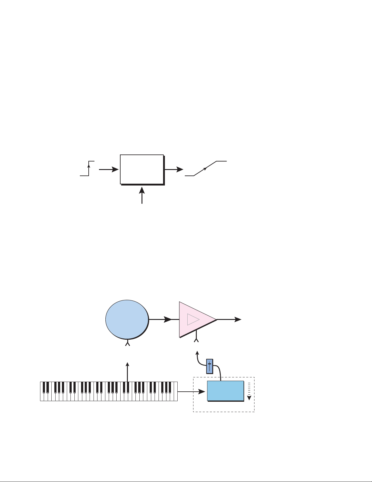
Channel Lag 1 & 2 Rate
Like the Layer Lag processors, the Channel Lag slows down rapid changes in the input
signal. The output “lags” behind the input at a pre-programmed rate.
Unlike the layer level lag processors, the Channel Lags 1 & 2 take effect as soon as the
preset is selected. In contrast, the Voice level lag processors begin acting only after a
keyboard key has been depressed. The Channel Lag also has a Lag Amount input which
controls the lag time. Positive lag amounts increase the lag time. A MIDI controller is
commonly used to control lag amount.
The Channel Lags could be used to slowly increase or decrease the speed of an LFO
which in turn controls some other effect, perhaps left/right panning, pitch, or the filter.
When a MIDI footswitch is used as the input, the lag acts to slow down the instantaneous change of the switch. The slowly changing output value can then be routed using
a patchcord to crossfade between voices or change the speed of an LFO.
Channel
Lag
ex. footswitch
4 - Preset Editor
Preset Globals
Lag Amount
(+ value = longer)
Poly Key Timer
This processor starts a timer which begins counting down whenever a key is pressed
and stops when the key is released. The value of this timer can be used on any voices
assigned to the key after the key release. The Poly Key Timer is a special modulation
source controlled by the key and not the voice.
Poly Key Timer can be used to control the volume of a Release Layer in order to reduce
its volume the longer a key is held. This control is commonly used on grand piano
presets to lower the pedal damper volume the longer the keys are held.
Release layer
voice becomes
softer the
longer the key
Release
Layer
Voice
Amp
is held.
Poly Release
Trigger
Amp Vol
Poly Key
Timer
Preset Global
Note-On - Poly Key Timer begins counting down.
Note-Off - Poly Key Timer stops counting and outputs value.
E-MU Systems 57
Page 58
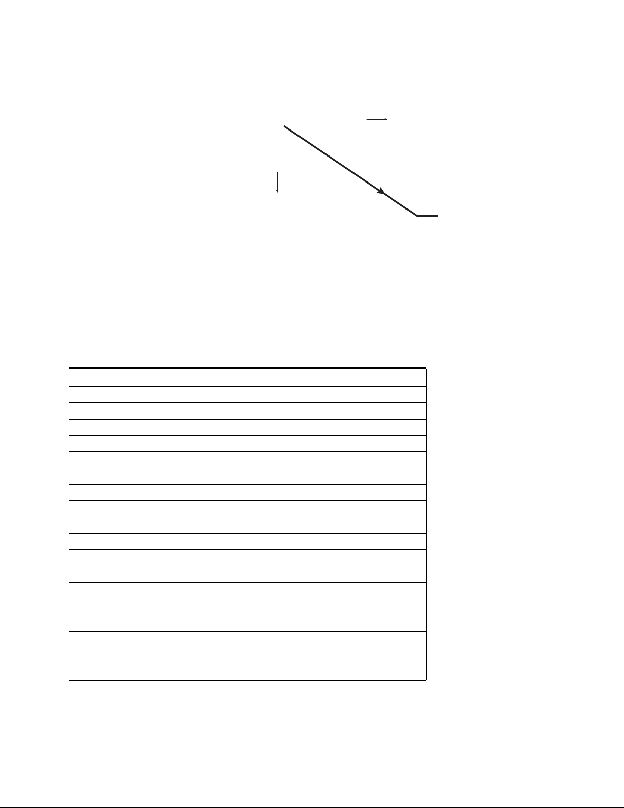
4 - Preset Editor
Preset Globals
Channel Ramp
This processor generates a single negative
going slope whenever the first key is
depressed on the MIDI channel. This preset
level processor was originally designed to
simulate the percussion key click on
Hammond organs, but you may find other
uses.
The Channel Ramp instantly resets when all
notes have been released and the next first
key on the MIDI channel is pressed. The
value of the ramp rate sets the increment.
Large values produce fast ramps and small
values produce slow ramps.
To use the Channel Ramp as a first-note
decay envelope, patch the Channel Ramp out to Amp Volume and set the Amp
Envelope for a fast attack and 100% sustain and short release.
decrease
1st Note
Played
Channel Ramp
time
Preset PatchCords
Preset PatchCords give you real-time control of the Preset Modulators. There are 8
Preset PatchCords per preset with a source, a destination and an amount control.
The amount can be set from -100 to +100.
Modulation Sources Modulation Destinations
Off Off
Pitch Wheel Channel Lag 1 In
Mod Wheel (Modulation Wheel) Channel Lag 1 Amount
Pressure (Channel Pressure) Channel Lag 2 In
Pedal Channel Lag 2 Amount
MIDI Volume (Controller 7) Channel Ramp Rate
MIDI Pan (Controller 10) Post-FX Main Send
Expression (Controller 11) Post-FX Aux 1 Send
MIDI A-P Post-FX Aux 2 Send
Footswitch 1 Post-FX Aux 3 Send
Flip-Flop Footswitch 1 (F’switch 1 FF) FX A Mod 1
Footswitch 2 FX A Mod 2
Flip-Flop Footswitch 2 (F’switch 2 FF) FX A Mod 3
Thumbswitch FX A Mod 4
Flip-Flop Thumbswitch (T’switch FF) FX B Mod 1
DC Offset FX B Mod 2
Channel Lag 1 & 2 FX B Mod 3
Channel Ramp FX B Mod 4
58 Proteus VX Operation Manual
Page 59
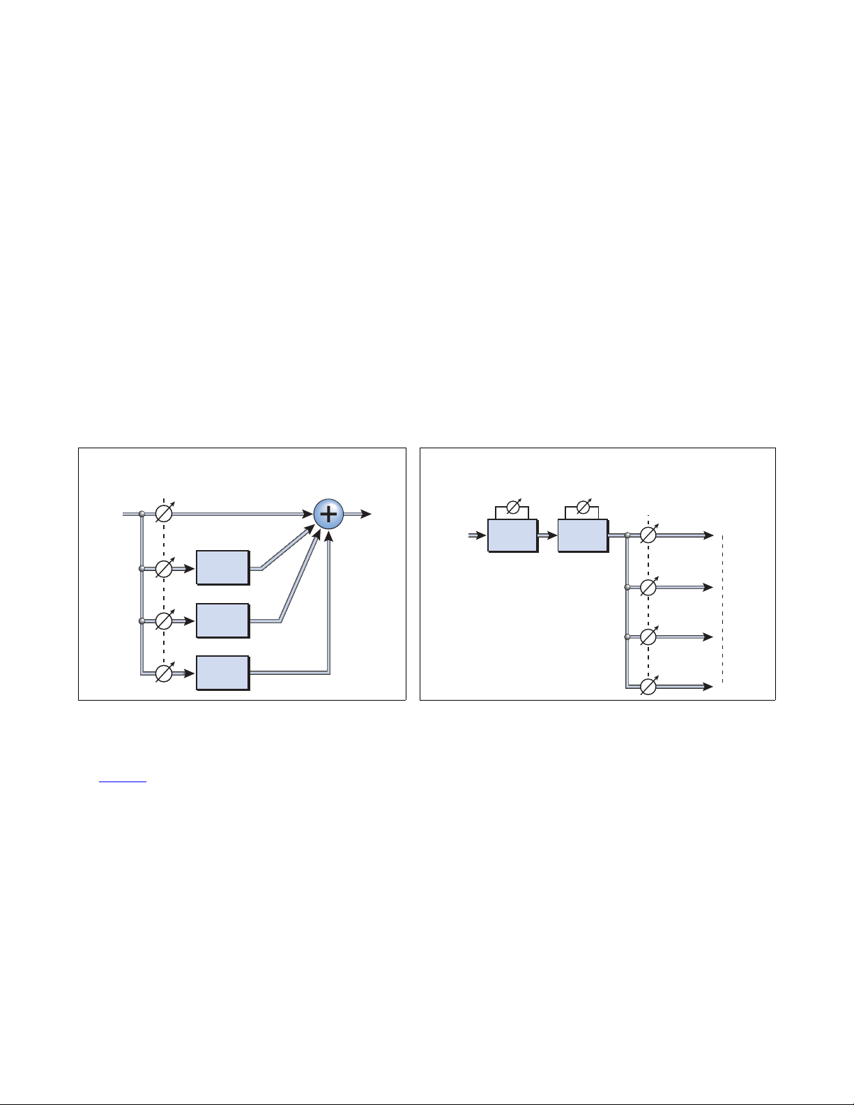
5 - Effects
t
t
Overview
In addition to the hardware-based effects of PatchMix DSP, Proteus VX offers software
effects processors and a powerful effects routing scheme. The E-MU engineers have
created a complete collection of top quality effects using 32-bit floating point precision
for pristine sound quality. In addition, the effects algorithms have been designed for
low CPU usage.
The Proteus VX effect routing architecture is extremely flexible. Effects can be included
as part of the preset or multisetup or both. Preset FX and Aux FX both use the same
effects algorithms.
• Multisetup (Aux) Effects are designed to be used for your main effects such as
reverb or delay. Aux effects can be applied to any or all of the 16 MIDI channels.
• Preset Effects are used when you want an effect to be included as part of a
certain preset. For example, you might want to add chorus to a string pad or
distortion to a guitar sound.
5 - Effects
Overview
Aux Effects in Sidechain
Amounts
From
Voices
Each effect has a number of user-adjustable parameters and a wet/dry mix control.
See page 22
real-time.
to learn how to use controllers to modulate various effects parameters in
MAIN
Aux 1
Effect
Aux 1
Effect
Aux 1
Effect
To
Hos
Preset Effects in Series
Wet/Dry
From
Voices
Wet/Dry
FXA FXB
Amounts
Main
Aux 1
Aux 2
Aux 3
To
Aux FX
or Hos
E-MU Systems 59
Page 60
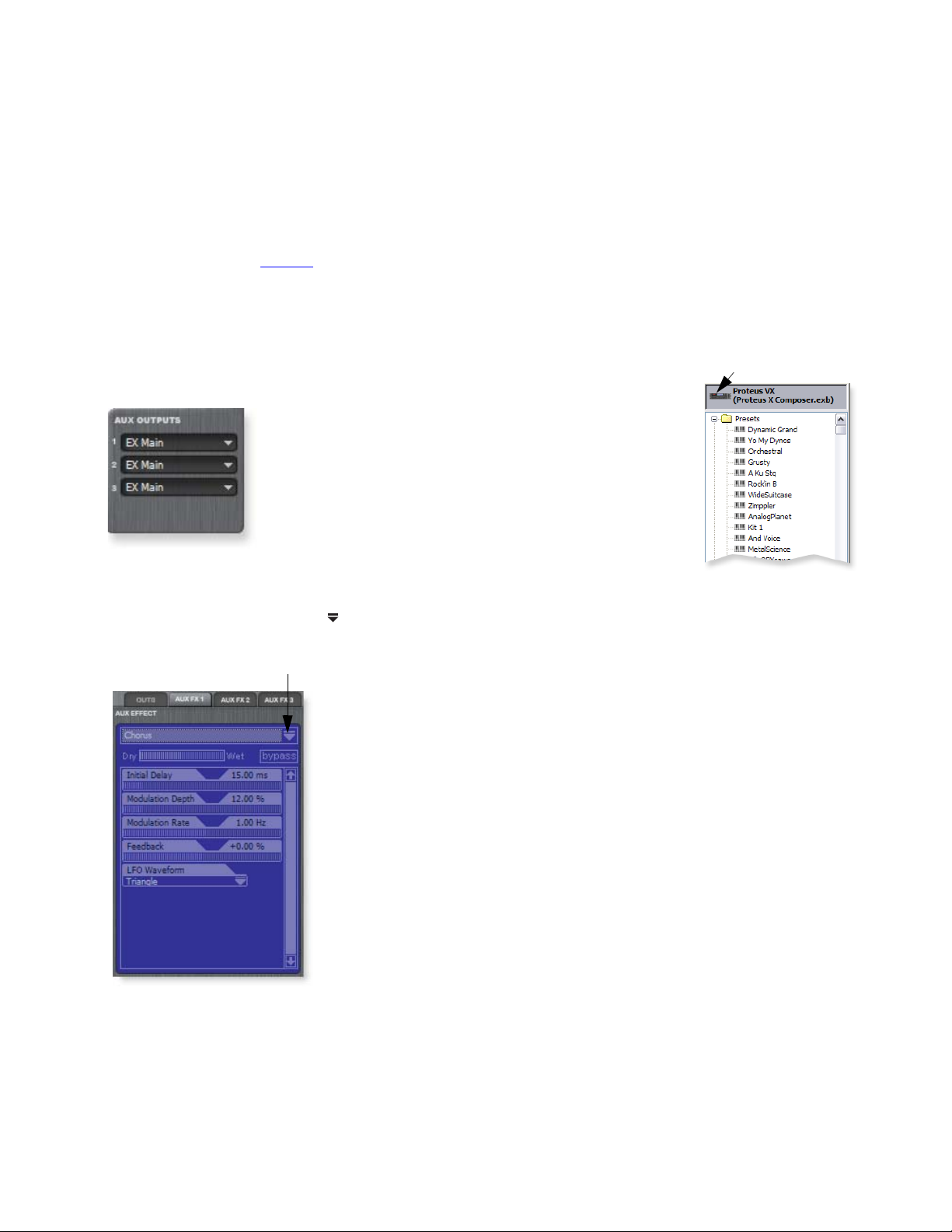
5 - Effects
Programming Effects
Programming Effects
Adding an Aux Effect in the Multisetup
Some banks (Proteus X Composer, for example) are already programmed to use
Proteus VX soft effects. These instructions explain how to add Aux Effects to a
Proteus VX bank which does not already have soft effects programmed.
The Aux Effects are designed to be used as sidechain effects applied on all presets in the
bank. See the diagram on page 62
How to Add an Aux Effect
1. Select the Multisetup Page by clicking the Proteus VX icon at the top of the tree.
2. Locate the Aux Outputs section in the lower right part of the window and make
sure all the Aux Outputs are set to Bus 1 as shown below. (This is done so all the
outputs go to the same place.)
for a complete description of the effects routing.
Proteus VX icon
3. Click on the Aux 1 button at the top right of the screen if it’s not already selected.
The Aux 1 effect appears in the TV screen.
4. Click on the Effect Select Icon at the top right corner of the Effects TV screen. A
list of available effects drops down.
Effect Select icon
5. Select one of the Effects from the list.
6. Turn up the FXA knob in the MIDI controllers section to hear the effect.
(FXA is located on Controller N.)
7. Change the effect parameters to suit your own taste, or change the entire effect for
that matter. Keep in mind that the changes you make will affect ALL the presets in
the bank.
8. Save the bank if you want to keep your changes.
60 Proteus VX Operation Manual
Page 61
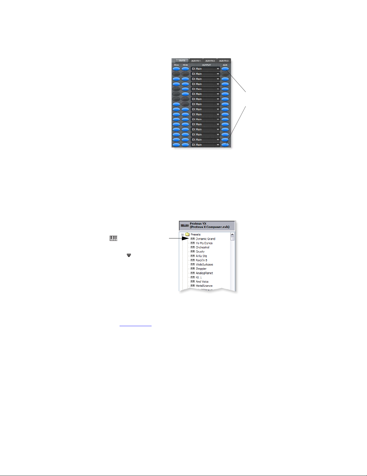
How to Temporarily Disable the Aux Effects
5 - Effects
Programming Effects
You might want to turn off the Aux effects to free
up CPU or just to hear the dry mix.
1. Select the Multisetup Page by clicking the
Proteus VX icon at the top of the tree.
2. Click on the 01-16 Button to select Multi-view
mode.
Aux
Enables
3. Click on the OUTS button near the top right
part of the screen. The screen shown at the
right appears.
4. The row of buttons marked AUX disable the
Aux outputs for each channel.
5. Turn the buttons off (grey) for the channels
on which you don’t want effects.
Adding an Effect to a Preset
Suppose you have a nice string sound, but you want to make it really thick and lush.
The obvious solution is to add a chorus. Since you only want the chorus to affect the
string sound, you’ll use a preset effect.
How to Add a Preset Effect
1. Select the preset you want in the tree by
clicking on the keyboard icon. The Preset
Global page appears.
2. Click on the Effect Select Icon at the top
right corner of the Effects TV screen. A list of
available effects drops down.
3. Select Chorus (or whatever effect you wish)
from the list. The Effect name is now listed
above the TV screen and the effect parameters
are shown in the TV screen.
4. Play the keyboard. You should now hear the selected effect as part of your sound.
If you don’t hear effects, make sure the FXA & FXB enable buttons are on for the
MIDI channel you are using. See page 62.
5. Adjust the Wet/Dry mix to control the effect amount.
6. Adjust the effect parameters until you find the sound you want or select a
Template.
7. Save the bank if you want to keep your changes.
The Aux buttons turn
all three Aux buses On or
Off.
Caution: If a preset
with effects is used on
more than one MIDI
channel, the CPU penalty
multiplies each time the
preset is used.
E-MU Systems 61
Page 62
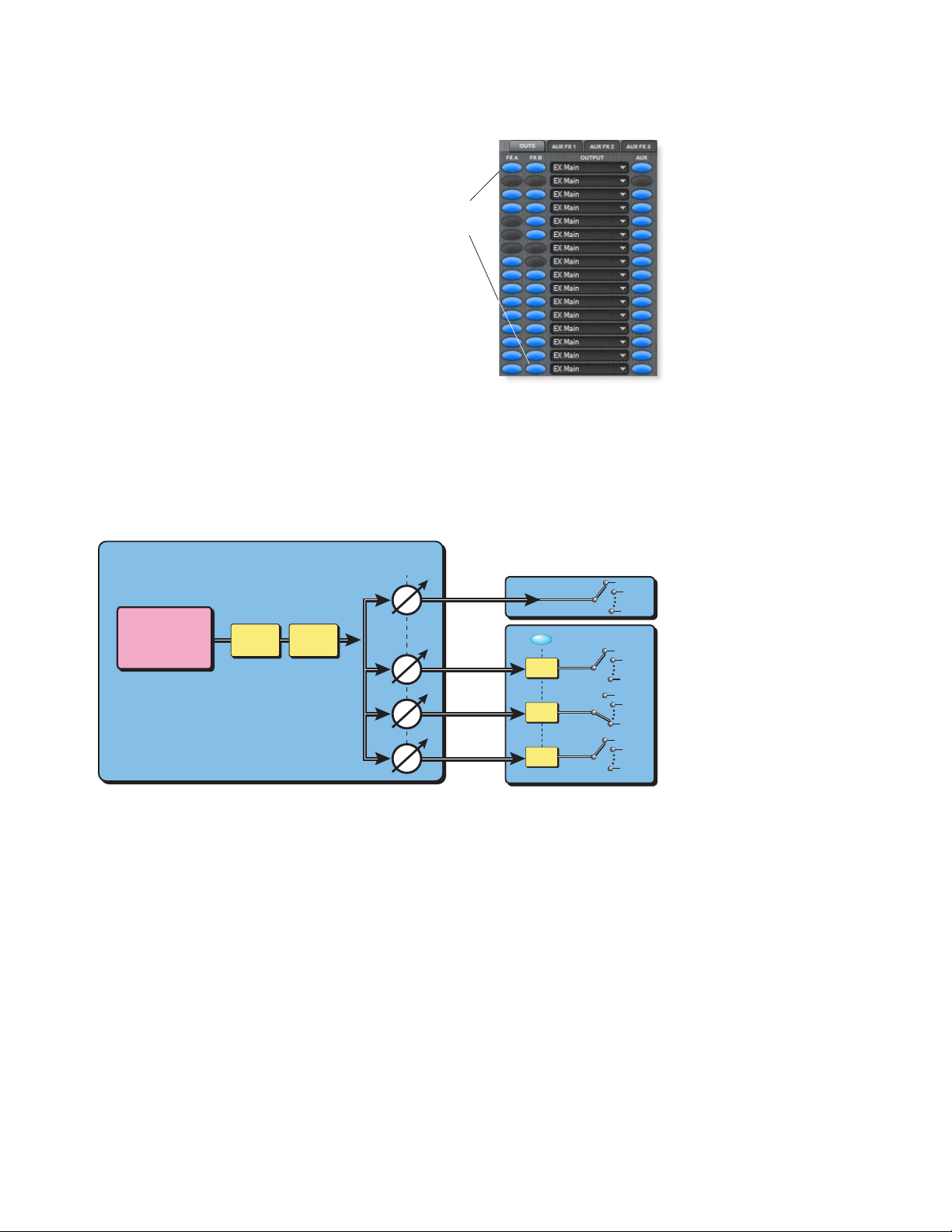
5 - Effects
Programming Effects
How to Temporarily Disable a Preset Effect
1. Select the Multisetup Page by clicking the
Proteus VX icon at the top of the tree.
2. Click on the 01-16 Button to select Multi-view
mode.
3. Click on the OUTS button on the top left of
FX
Enables
the screen. The screen shown at the right
appears:
4. The two rows of buttons marked FXA and FXB
enable or disable the preset effects for each
channel.
5. Turn the buttons off (grey) for the channels
you are using if you don’t want to use the
effects.
Block Diagram of the Effects Routing
PRESET
Post FX
Sends
Main
SAMPLES
&
VOICES
Two effects can be assigned per Preset. Three effects can be assigned per Multisetup.
FX A
FX B
Aux 1
Aux 2
Aux 3
MULTI
On/Off
Aux 1
FX
Aux 2
FX
Aux 3
FX
BUS 1
BUS 19
BUS 1
BUS 19
BUS 1
BUS 19
BUS 1
BUS 19
BUS 2
BUS 2
BUS 2
BUS 2
62 Proteus VX Operation Manual
Page 63
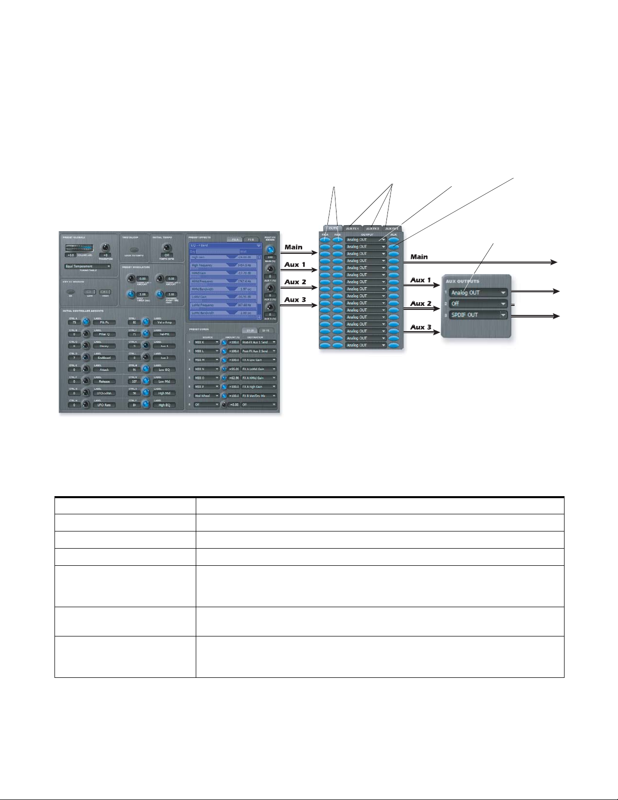
FX Routing
Make sure that you are thoroughly familiar with the architecture of Proteus VX, before
delving into the effects section and it will make a lot more sense. Study the effect
routing diagrams below and the preceding page. The effects architecture of the Proteus
VX is very flexible and allows for a variety of different signal routing schemes.
5 - Effects
FX Routing
Block Diagram of the Effects Screens
Preset Effects
A & B On/Off
Aux Effect
View
Main Output
Bus Select
Aux Output
Bus Select
Aux Out
Assignment
Aux Output
On/Off
Main Out
Main Out
Off
S/PDIF Out
MULTI
(only visible in 1-16 view)
PRESET
This diagram shows the effects routing using the actual Proteus VX screens in the Preset and Multisetup.
The Main output and the Aux 1 outputs are both routed to the Main Output and will be combined in the Host application.
Preset - Main Output
Preset - Aux Outputs 1-3
Multi - Effects A & B On/Off
Multi - Aux Effect View
Multi - Main Output Bus
Adjusts the amount of Preset Effect signal that will be sent to the Main Output.
Adjusts the amount of Preset Effect signal that will be sent to the Aux 1-3 buses.
These buttons enable or disable the Preset A & B effects for each MIDI channel.
These buttons let you see the Main output screen or the Aux 1-3 effect screens.
This field allows you to select the channel pair for the Main Output.
(Bus outputs appear in the list only after they have been created in Proteus VX
Preferences.)
Multi - Aux Output On/Off
This button turns the Aux outputs on or off for each MIDI channel. In the factory
presets, this button effectively enables or disables the global effects.
Multi - Aux Output Bus
This field allows you to select the channel pair for Aux Outputs 1-3.
(VSTi Bus outputs appear in the list only after they have been created in Proteus VX
Preferences.)
E-MU Systems 63
Page 64

5 - Effects
FX Routing
You can place effects in two places:
• Multisetup - - - - - - -Effects placed in the Multisetup (Aux 1, Aux 2 or Aux 3)
can be used by all Presets in the Bank.
• Preset - - - - - - - - - - - Effects placed in the Preset (FXA or FXB) are used by one
specific Preset.
Effects Overhead
Each effect you select, whether it is located in a Preset or in the Multisetup, uses a
percentage of your computer’s CPU. Extensive use of effects in every preset can easily
bog down your computer. Effects begin running (and using CPU) as soon as they are
selected.
Typical Effects Usage
Because the software effects use precious CPU resources, you will generally use Aux
effects in the Multisetup for your main effects, since these can be shared by all presets
in the bank. You can still use Preset Effects as needed, keeping in mind that the more
software effects you use, the fewer CPU resources will be available for polyphony,
recording and other tasks.
VSTi Bus Outputs
Bus outputs (Bus 1-19) appear in the list only after they have been created in the
Proteus VX Preferences dialog.
If a Preset containing
an effect is used by more
than one MIDI channel,
more CPU resources are
used.
64 Proteus VX Operation Manual
Page 65
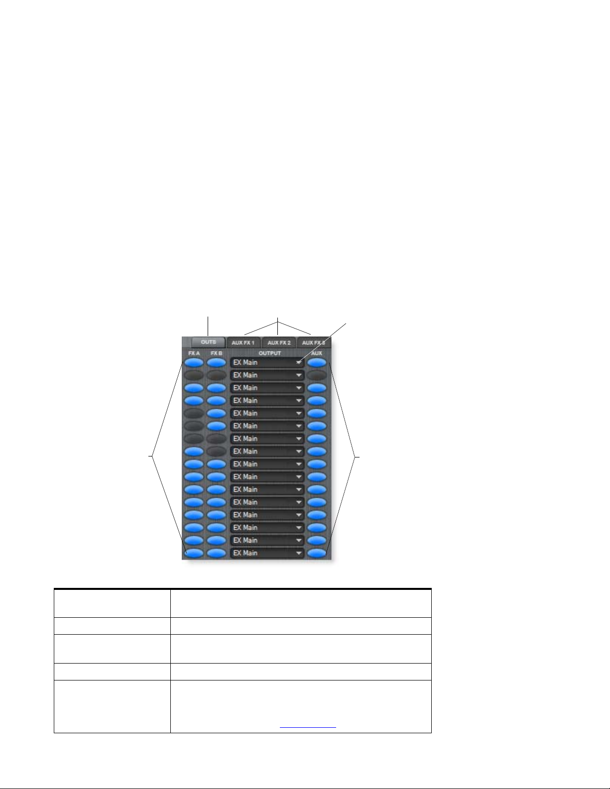
Main Output Window
The Main Output window is accessed by clicking the Outs button. (This option is not
available in “Single” mode.) This one window allows you to set the Host Application
Bus routing of the Main Output, enable the Preset Effects, and enable the Aux Outputs
for each MIDI channel. This window is extremely handy for turning all your effects on
or off.
The Preset Effect On/Off buttons are used to temporarily disable the selected A or B
effect while passing the signal. These controls allow you to hear each preset with or
without effects or to turn off all Preset Effects in order to gauge the CPU load incurred
by the Preset Effects.
The Aux Output On/Off buttons work differently than the Preset Effect On/Off
buttons and completely turn off the three Aux Sends for the selected channel. When
using the factory presets, the Aux Output buttons are used to enable or disable the Aux
Effects (because all outputs are connected to Bus 1. If you were using the Aux buses to
send signals to other Buses, the Aux button could be used to turn these outputs on or
off.
5 - Effects
Main Output Window
Main Output
Window
Preset
Effects
On/Off
Output
View
Aux1-3
Select
Main Output
Routing
Aux
Output
On/Off
Output View
Selects the Main Output Window.
(Note: This button is disabled in “Single” mode.)
Aux 1-3 Select
Preset Effects On/Off
Select between Aux 1, Aux 2, or Aux 3 FX in the TV view.
Turns the Preset A or B effects On or Off for each MIDI
channel and passes the signal through.
Main Output Routing
Aux Output On/Off
E-MU Systems 65
Selects the Bus number for the Main Output. See tip -->
Turns the Aux Outputs On or Off for the selected channel.
This turns all three Aux Outputs Off, rather than bypassing
the effects. (Functions as an FX Bypass when the Proteus X
Composer bank is used. See page 66.
)
The number of VSTi
buses must be defined in
the Proteus VX Preferences
before they appear in this
list.
Page 66
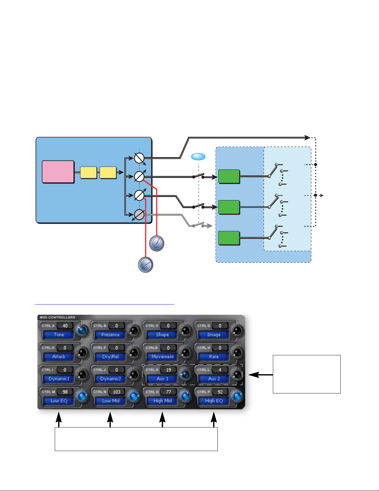
5 - Effects
Proteus X Composer FX Template
Proteus X Composer FX Template
This is the effects architecture we have chosen to use for the Proteus VX Composer
bank. Preset effects and global effects can be used simultaneously and you can use
Cubase LE or PatchMix DSP hardware effects by simply changing the Aux Output
routing.
The main effects are located in the Multisetup so that they can be shared by all presets.
This is the standard sidechain effects routing scheme found on all mixing boards.
Aux 1 = Reverb and Aux 2 = BPM Delay. MIDI controller K controls Reverb amount
and MIDI controller L controls Delay amount through the Preset PatchCords.
PRESET
Post FX
SAMPLES
&
VOICES
FX A
FX B
Sends
Main
Aux 1
On/Off
Reverb
Aux 1
Aux Outputs
Bus 1
Aux 2
Aux 2
Aux 3
BPM
Delay
Off
Aux 3
Not
K
MIDI
L
Controllers
Used
MULTI
(Preset Cords)
MIDI Controllers M, N, O, and P control various parameters of the Preset FX. You can
change the destinations of these controls using the Preset PatchCords.
Preset FX Modulation Parameters” on page 69.
See “
Bus 1
Bus 1
Bus 1
Controllers K & L
Control Aux FX Amounts
Aux 1 = Reverb
Aux 2 = Delay
Controllers M-P
Control Preset Effect Parameters
(These are custom programmed for each preset.)
66 Proteus VX Operation Manual
Page 67
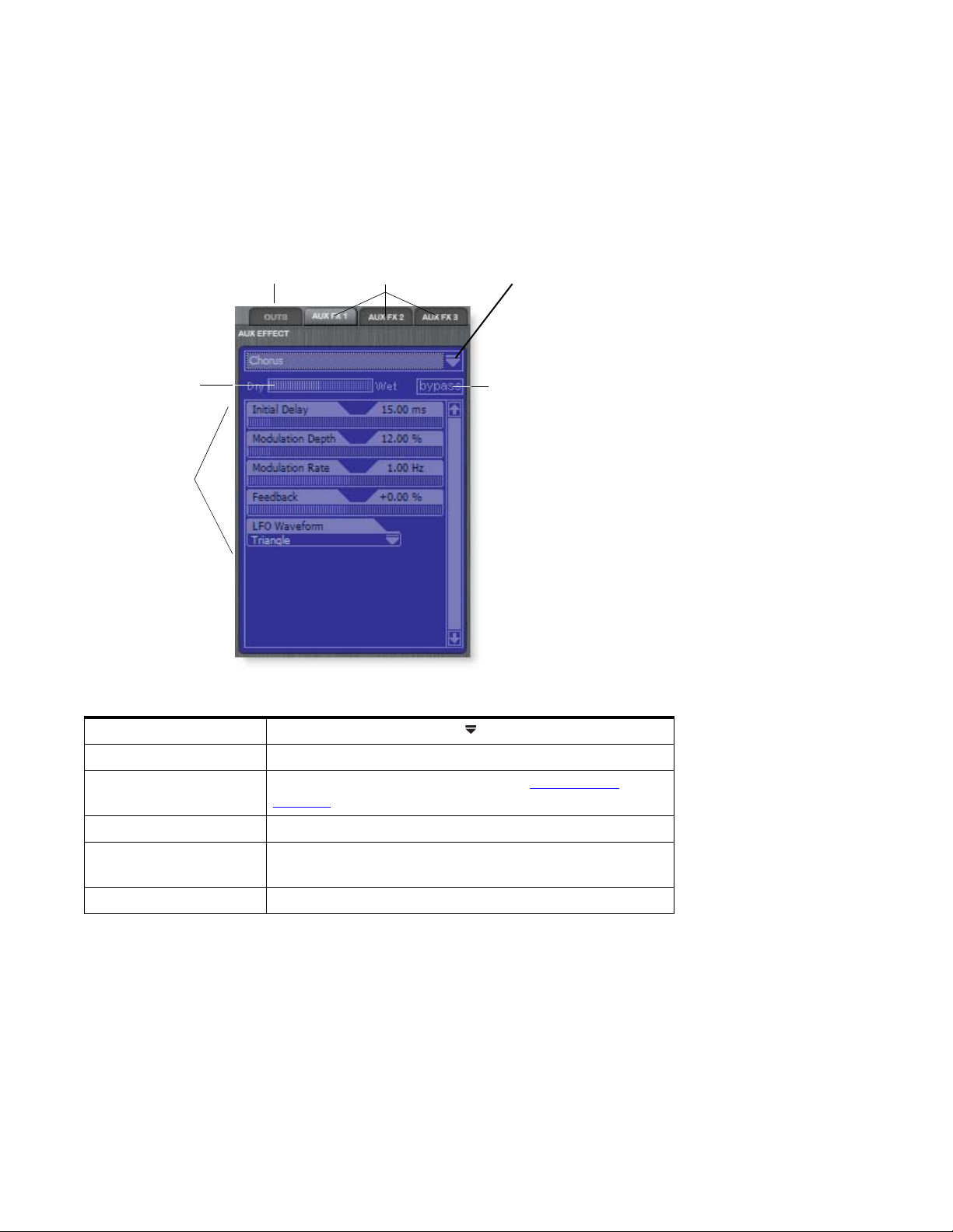
Aux FX Screen
All effects have a wet/dry mix parameter to control the ratio of effected-to-plain signal,
which is stored with the FX preset. The effect parameters vary with the type of effect.
Generally, when using the Aux Effects, the wet/dry mix in the effect should be set to
100% wet since the Aux Send amount controls how much effect will be applied.
5 - Effects
Aux FX Screen
Aux Effects
Wet/Dry Mix
Control
Effect
Parameters
Output
View
Aux1-3
Select
Effects List
Effect
Bypass
Effects List
Aux 1-3 Select
Output View
Wet/Dry Mix Control
Effect Bypass
Effect Parameters
Click on the Effects List icon to show the list of effects.
Select between Aux 1, Aux 2, or Aux3 FX in the TV view.
Selects the Main Output Window. See Main Output
Window. (Note: This button is disabled in “Single” mode.)
Adjusts the ratio of effected signal to un-effected signal.
When this button is selected (Red), the effect is completely
bypassed, allowing you to hear only the uneffected signal.
Each effect has its own set of user adjustable controls.
E-MU Systems 67
Page 68
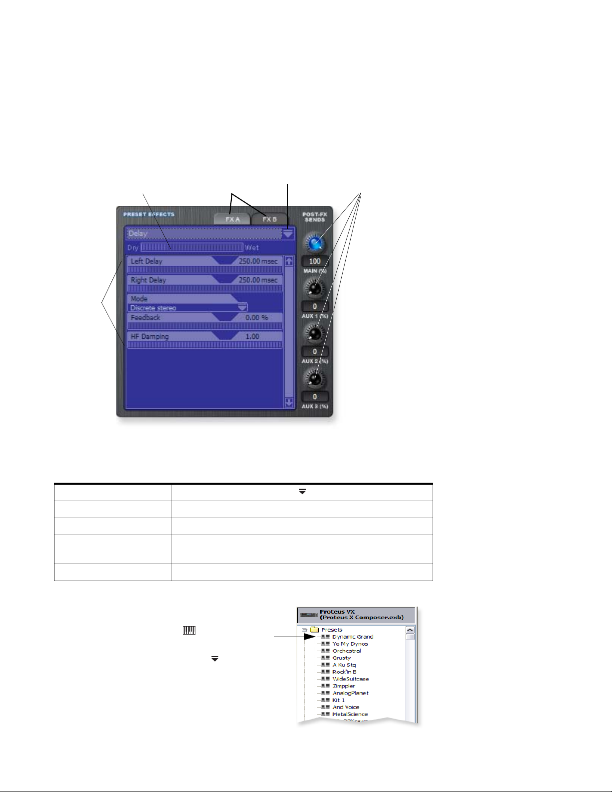
5 - Effects
Preset FX Screen
Preset FX Screen
All effects have a wet/dry mix parameter to control the ratio of effect-to-plain signal,
which is stored with the FX preset. Each effect has its own set of control parameters.
Turn up the Wet/Dry mix to hear more effect while you adjust the parameters, then
turn the amount down to the desired effect amount.
Preset Effects
Effect
Parameters
Wet/Dry Mix
Control
FXA / FXB
Select
Effects List
Post FX
Send Amounts
Effects List
FXA / FXB Select
Wet/Dry Mix Control
Post FX Send Amounts
Click on the Effects List icon to show the list of effects.
Select between FXA or FXB in the TV view.
Adjusts the ratio of effected signal to un-effected signal.
Adjusts the amount of preset effect signal that will be sent
to the Main and Aux Outputs.
Effect Parameters
To Get to the Preset FX Screen
Each effect has its own set of controls.
1. Select the preset you want in the tree by
clicking on the keyboard icon. The
Preset Global page appears.
2. Click on the Effect Select Icon at the top
right corner of the Effects TV screen. A list of
available effects drops down.
68 Proteus VX Operation Manual
Page 69
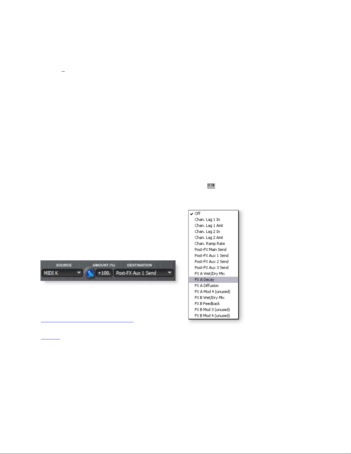
To Swap FXA and FXB
Effects can sound very different depending on their order in the chain. Here is a simple
way to swap FXA and FXB.
5 - Effects
Preset FX Screen
1. Choose S
wap Effects from the Preset pull-down menu.
2. The two effects will exchange positions.
Preset FX Modulation Parameters
Certain parameters in each Preset Effect can be controlled from the Preset Cords. Some
effects (such as BPM delay) allow four controllable parameters, while other effects
(such as Early Reflections) have only one controllable parameter. If an effect uses less
than four parameters, the idle cords are listed as (unused). See below.
The Preset Cord value ADDS to the setting made in the Preset FX screen. For example, if
the Wet/Dry Mix were set to 0% and you patched a MIDI Controller to Wet/Dry Mix
with an amount of +100, the MIDI Controller would have a full range of control over
Wet/Dry Mix. To invert the control, simply set the initial Wet/Dry Mix to 100% and set
the Cord amount to -100.
How to Connect MIDI Controllers to FX Parameters
1. Select the preset you want in the tree by clicking on the keyboard icon.
The Preset Global page appears.
2. Assign FXA or FXB in the Preset FX screen.
3. Select the Destination field from the Preset Cords
section. A list of all possible Preset Cord destinations
appears.
4. The effect modulation parameters are at the bottom of
the list. Select the parameter you wish to control.
5. Select the Modulation Source you wish to use.
6. Set the Cord Amount.
7. In the screen above MIDI Controller K is controlling the
Reverb Decay Time.
See MIDI Channels & Real-time Controls
to learn how MIDI
controllers work in the Proteus VX.
See page 22
to learn how to assign MIDI controller numbers to the Proteus’s A-P
reference letters.
E-MU Systems 69
Page 70
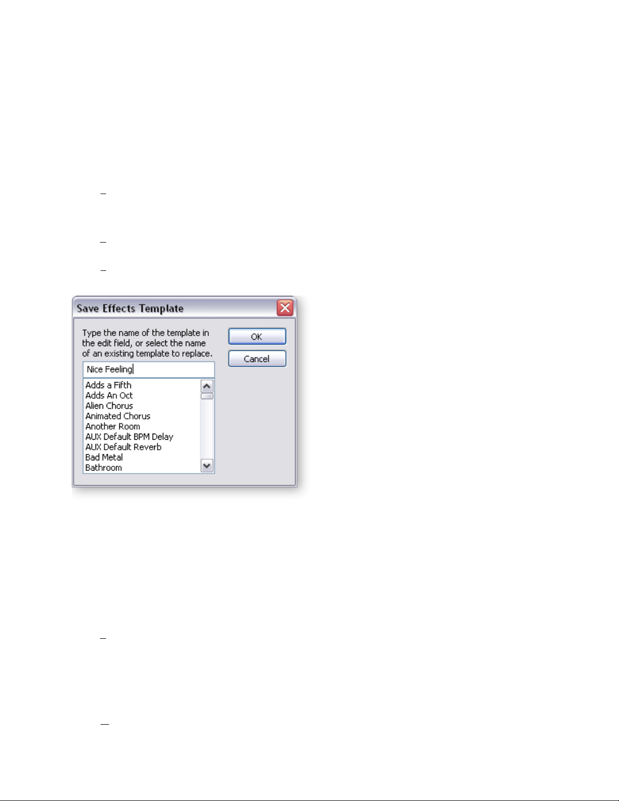
5 - Effects
Preset FX Screen
Creating, Deleting & Reordering Templates
You can save a library of your favorite effects as Templates. Templates are saved with the
Proteus VX application so they’re always available for use.
To Create an Effect Template
1. Set the controls as desired for a particular effect.
2. Right-click with the mouse anywhere inside the TV screen border. A pop-up menu
appears.
3. Select S
The following popup dialog box appears.
OR…
ave Effects Template or press “S” while the popup dialog box is visible.
1. Select E
ffects Templates or press “E” from the Multisetup, Preset or Voice menus.
A pop-up list of Templates appears.
2. Select S
ave Effects Template or press “S” while the popup dialog box is visible.
The following popup dialog box appears.
3. Type in a name for your Template and click OK. The Template is saved with the
editor program, ready to use when you open any bank.
To Recall a Template
1. Right-click with the mouse anywhere inside the module border. A pop-up menu
of Templates appears.
2. Select the desired Template from the list. The Template will be selected.
OR…
1. Select E
ffects Templates or press “E” from the Multisetup, Preset or Voice menus.
A pop-up list of Templates appears.
2. Select the Template you want and click OK.
To Rename o r Delete a Te m p l at e
1. Right-click with the mouse anywhere inside the module border.
2. Select O
70 Proteus VX Operation Manual
rganize Templates. The following menu appears.
Page 71
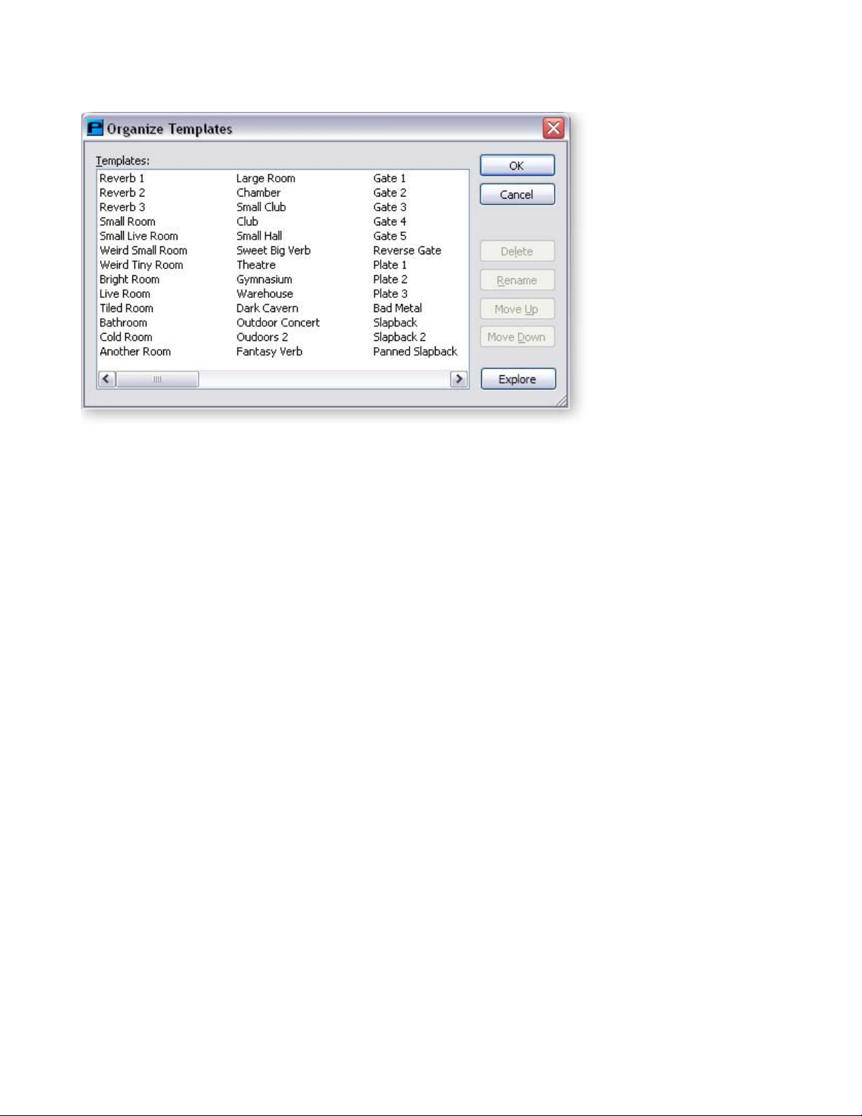
3. Click Delete to permanently remove the Template.
4. Click Rename, then type in the new name to rename the Template.
5. Click OK to close the dialog box.
5 - Effects
Preset FX Screen
To Change the Order of the Templates
1. Right-click with the mouse anywhere inside the module border.
2. Select Organize Templates. The menu shown above appears.
3. Click Move Up to move the Template one space up in the list.
4. Click Move Down to move the Template one space down in the list.
5. Click OK to close the dialog box.
To Explore Templates Folders
1. From the Organize Templates dialog box, click Explore.
2. Explore the templates on your computer.
3. Proteus VX stores your templates in the following folder:
\Program Files\Creative Professional\Emulator X Family\Templates\
When you click Explore, you are taken to this directory. From here, you can copy or
restore existing templates for backup purposes. You can also modify the .xml files with
an XML editor.
E-MU Systems 71
Page 72
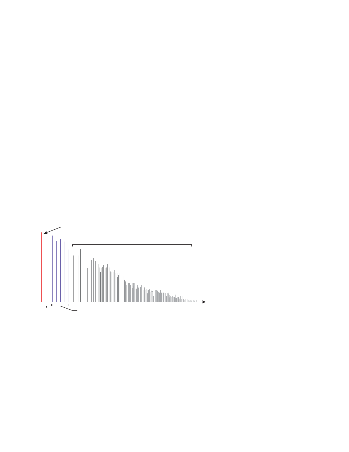
5 - Effects
Effects Listing
Effects Listing
Reverb Delay (mono) Phaser
Early Reflections Reverb Early Reflections Pitch Shifter (mono)
Reverb Lite (mono) EQ - 1Band Parametric Ring Modulator
Chorus EQ - 4 Band SP12-ulator
Chorus / Delay (mono) Flanger Tremulator BPM
Compressor Flanger (BPM) Tube
Delay Growl Twin (mono)
Delay (BPM) Limiter
Effects Descriptions
Background: Reverb
This information applies to all the reverb algorithms.
Reverberation is a simulation of a natural space such as a room or hall. Pre-delay is the
time before the reflections from the closest walls are heard. This parameter gives our
ears important clues about the size of a room. As you might imagine, large halls have a
longer pre-delay than small rooms.
Decay Time defines the time it takes for the reflected sound from the room to decay or
die away. The diagram below shows a generalized reverberation envelope.
Initial Sound
Reverberation
Pre-Delay
After a short pre-delay period, the echoes from the closest walls or ceiling are heard.
The pattern of these first echoes, or Early Reflections, vary greatly depending on the
type of room. Some time after the early reflection cluster ends, the actual Reverber-
ation
(a dense cloud of complex wall reflections) begins and decays according to the time set
by the Decay parameter.
Diffusion is the amount of scattering and density of the reverberation cloud. Rooms
with many complex surfaces have more diffusion than bare rooms.
High frequency energy tends to fade away first as a sound is dissipated in a room. The
High Frequency Damping parameter adjusts the time it takes for the high frequency
energy to die away and thus changes the characteristics of the room. Rooms with
smooth, hard surfaces are more reflective and have less high frequency damping.
Rooms filled with sound absorbing materials, such as curtains or people, have more
high frequency damping.
Early Reflections
Time
72 Proteus VX Operation Manual
Page 73
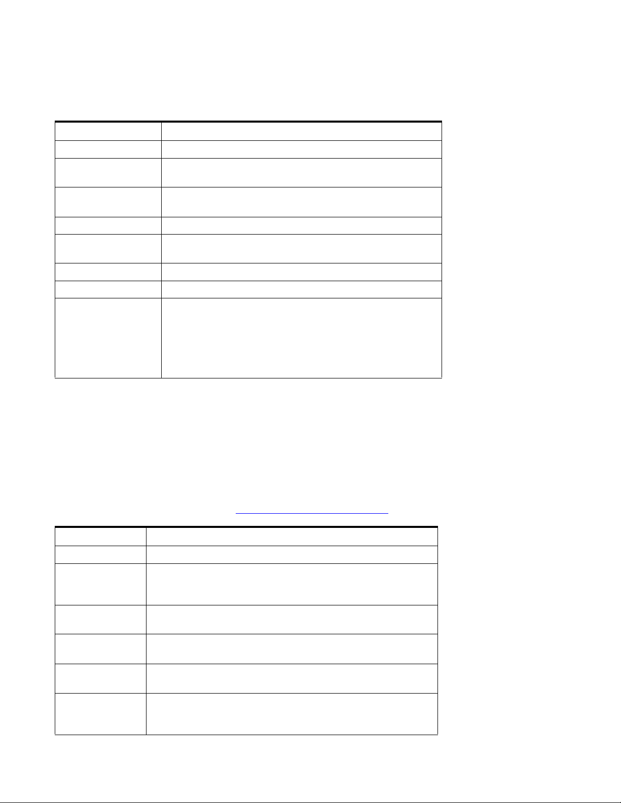
Reverb
The Reverb is a medium load reverb, designed to simulate various types of rooms, halls
and plates.
Parameter Description
Decay Sets the decay time of the entire effect.
Diffusion Sets the amount of scattering of the reverb cloud. Note that
high diffusion settings will increase the overall decay time.
Room Size Changes the spacing of the reverb stages to simulate rooms of
various shapes and sizes.
Early Reflections Sets the volume of the initial wall reflections.
Pre-Delay Sets the amount of time before any reflected sound is heard.
Range:1millisecond to 200 milliseconds
High Freq. Damping Sets the rate at which high frequencies die away.
Low Freq. Damping Sets the rate at which low frequencies die away.
5 - Effects
Effects Descriptions
Stereo Mode Independent - In this mode, the left and right sides function
as completely separate reverb units.
Figure Eight - This mode incorporates criss-cross feedback in
which the left channel feeds the right and vice-versa.
Matrix - This mode utilizes multiple feedback paths to create a
spacious, natural sound.
Modulation Parameters
• Wet/Dry Mix
•Decay
• Diffusion
Early Reflections Reverb
The Early Reflections algorithm is the most resource-intensive reverb model and has
the most adjustable parameters. This reverb is designed to simulate various halls,
rooms and reverberation plates. See also “
Parameter Description
Pre-Delay Sets the amount of time before any reflected sound is heard.
Early Reflection
Mode
Selects the pattern of the early reflections. Select between: Hall 1,
Hall 2, Hall 3, Room, Spiral, Multitap, 6 tap, 12 tap, 12 tap rising,
or up & down.
Early Reflection
Room Size
Early Reflection
L/R Spacing
Scales the spacing of the early reflections to simulate rooms of
different sizes.
Scales the spacing of left side reflections versus the right side, to
create a more interesting stereo image.
Background: Reverb” on page 72.
When using the
Figure Eight or Matrix
modes, pan position will
be less focused and the
stereo image will be
somewhat blurred.
Early Reflection /
Tail Balanc e
Allows you to balance the relative volumes of the early reflections
and the reverberation cloud. 0% to 100%
HF Damping High Frequency Damping cuts the High Frequency content to
simulate soft, absorbent surfaces such as draperies, wood or
people.
E-MU Systems 73
Page 74
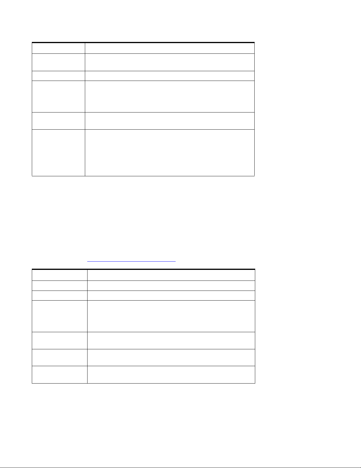
5 - Effects
Effects Descriptions
Parameter Description
LF Damping Low Frequency Damping cuts the Low Frequency content to
simulate hard, reflective surfaces such as tiles or stone.
Tail Decay Sets the decay time of the reverberation cloud. (RT60)
Tail Diffusion Sets the amount of scattering of the reverb cloud. At low settings,
discrete echoes are heard. At high settings a diffuse wash of
sound is heard. High diffusion settings will increase the overall
decay time.
Tail Room Size Changes the spread of the reverberation cloud echoes,
simulating rooms of various sizes and shapes.
Tail Stereo Mode Independent - In this mode, the left and right sides function as
completely separate reverb units.
Figure Eight - This mode incorporates criss-cross feedback in
which the left channel feeds the right and vice-versa.
Matrix - This mode utilizes multiple feedback paths to create a
spacious, natural sound.
Modulation Parameters
• Wet/Dry Mix
•Decay
• Diffusion
Reverb Lite (mono)
The Reverb Lite is a monophonic, slimmed down version of the Big Reverb. This effect
only uses about 3/4 of the DSP resources of the Big Reverb, (and is smaller than even
the Chorus effect) making it the perfect choice when you’re running low on CPU
horsepower. See also “
Parameter Description
Pre-Delay Sets the amount of time before any reflected sound is heard.
Decay Sets the overall decay time of the reverberation effect.
Diffusion Sets the density of the echoes and scattering of the reverb cloud.
Background: Reverb” on page 72.
At low settings discrete echoes will be heard, At high settings a
dense wash of sound is produced. Note: High diffusion settings
will increase the overall decay time.
When using the
Figure Eight or Matrix
modes, pan position will
be less focused and the
stereo image will be
somewhat blurred.
Room Size Changes the spacing between the reverb stages to simulate
rooms of various shapes and sizes.
HF Damping High Frequency Damping sets the rate at which low frequencies
die away. A setting of zero results in no damping.
Pan This parameter sets the position of the reverberant sound in the
stereo field, in order to change the apparent source position.
Modulation Parameters
• Wet/Dry Mix
•Decay
•Pan
74 Proteus VX Operation Manual
Page 75
Chorus
Background: Chorus
An audio delay in the range of 15-20 milliseconds is too short to be an echo, but is
perceived by the ear as a distinctly separate sound. If we now vary the delay time in this
range, an effect called chorus is created, which gives the illusion of multiple sound
sources. A slight amount of feedback serves to increase the effect. Inverted feedback
percentages add negative feedback which can change the tone of the chorus. A very
slow LFO rate is usually best for a realistic effect, but a faster LFO rate can also be useful
with minimal LFO depth (.2).
This effect is a true-stereo chorus with independent delay lines for the left and right
channels. The left and right modulation waveforms are always 180° out of phase, so
that left channel delay is increasing while the right channel delay is decreasing and
vice-versa. This creates a richer and more animated chorus sound.
Parameter Description
Initial Delay Sets the length of the delay. Range: 10ms to 50ms.
5 - Effects
Effects Descriptions
Modulation
Depth
Modulation
Rate
Feedback Sets the polarity and amount of delayed signal that will be recirculated
LFO Waveform Selectable between Sine or Triangle wave.
Sets how much the LFO affects the delay time. Increases the
animation and amount of the chorus effect. Range: 0% to 100%
Sets the frequency of the low frequency oscillator.
Range:.01Hz to 15Hz
through the delay lines. Range: -99% to +99%
Modulation Parameters
• Wet/Dry Mix
• Rate (LFO)
• Feedback
E-MU Systems 75
Page 76
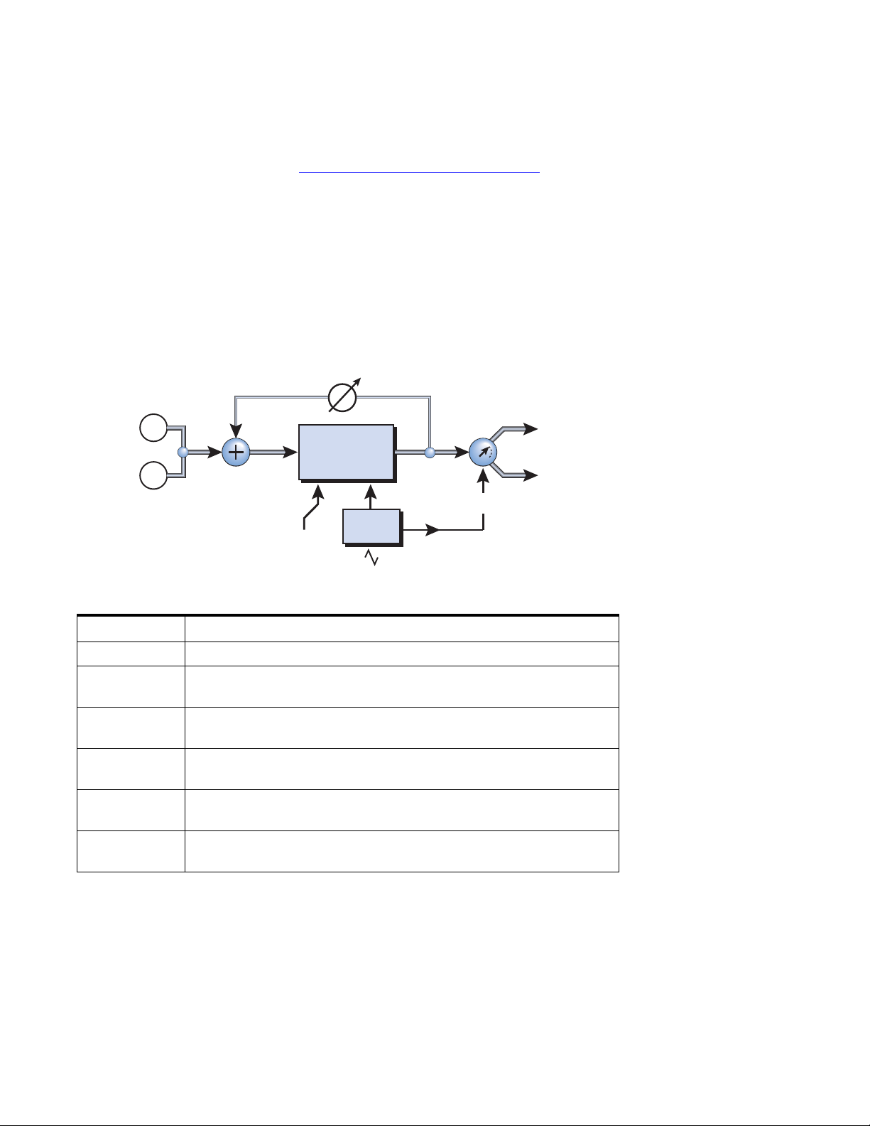
5 - Effects
Effects Descriptions
Chorus / Delay
This effect is a combination Chorus and Delay because the signal can be delayed up to
a full second (1000ms). Slightly modulating the delay time in the 15-20ms range
produces the familiar chorus effect. See “
When a longer delay is modulated, a kind of gliding pitch shift effect is produced.
Vibrato effects can be easily created by adjusting the modulation rate and modulation
depth parameters. When feedback is introduced to a long modulated delay, the sound
tends to get scrambled up in unpredictable ways which might be just the thing to create
that “swarming bees” effect you’ve been looking for.
Setting the feedback percentage in the negative range, inverts the feedback signal.
Negative feedback has the effect of deepening the cancellation notches which are
created when using short delays with feedback.
Background: Chorus” on page 75.
Feedback
Very short delay times
combined with a high
feedback amount can be
used to create monotone
robotic-sounding effects.
L In
L Out
Delay
R In
R Out
Panning
LFO
Initial
Delay
Parameter Description
Initial Delay Sets the length of the delay line. Range: 10ms to 1000ms.
Modulation
Depth
Modulation
Rate
Feedback Sets the polarity and amount of delayed signal that will be recirculated
Pan This parameter moves the delayed sound left or right. This moves the
LFO -> Pan Sets the amount of panning that will occur at the Modulation Rate
Sets how much the LFO affects the delay time. Increases the amount
of chorus effect and pitch shift animation. Range: 0% to 100%
Sets the frequency of the low frequency oscillator.
Range: .01Hz to 15Hz
through the delay line. Range: -99% to +99%
apparent sound source left or right. Range: -99% to +99%
Range: -99% to +99%
Modulation Parameters
• Wet/Dry Mix
• Rate (LFO)
• Feedback
•Pan
76 Proteus VX Operation Manual
Page 77
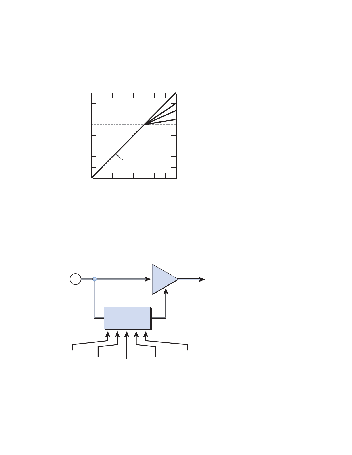
Compressor
ut
In its simplest form, an audio compressor is just an automatic gain control. When the
volume gets too loud, the compressor automatically turns it down. Compressors are
useful in musical applications because they smooth out dynamic volume changes and
provide a louder average signal level.
5 - Effects
Effects Descriptions
0dB
-30dB
-80dB
Since the compressor turns down the gain of the signal, you might wonder how can it
make the signal level stronger. An Output Gain control allows you to boost the output
gain of the compressor in order to make up for the gain reduction. The overall level is
higher and only turned down when the signal level gets too loud. The level at which the
volume gets turned down is called the Threshold, which just happens to be the most
important control on the compressor.
Threshold: -30dB
Ratio
Signal Level
1:1
1.5:1
2:1
10:1
Basic Controls
The three main controls of a compressor are the Ratio control, the Threshold control
and the Output Gain control.
Signal path = Stereo
In
VCA
O
Level
Control
Threshold
Ratio
Attack
Release
Output Gain
If the signal falls below the Threshold, no processing will take place. Signals exceeding
the Threshold will have gain reduction applied as set by the ratio control. This
important control allows you to dial in the range of amplitudes you want to tame. For
example, if you’re trying to trim off just the loudest peaks, set the threshold high so
that compression only occurs during these peaks. One of the biggest mistakes in
E-MU Systems 77
Page 78
5 - Effects
Effects Descriptions
using a compressor is having the threshold set too low. This adds noise as the
compressor will always be reducing the volume.
The Ratio control determines how strongly the compressor will affect the signal. The
higher the ratio, the more reduction will be applied. If the ratio is high enough, (10:1)
the signal will effectively be prevented from getting any louder. In this situation, the
compressor will be acting as a Limiter, placing an upper limit on the signal level. In
general, ratios from 2:1 to 6:1 are considered compression and higher ratios above
10:1 are considered limiting.
The Output Gain control amplifies the signal after it has been compressed to bring it
back up in volume. If you don’t increase the gain, the compressed signal will be much
lower in volume.
Two other important controls are Attack and Release. Attack controls how quickly the
gain is turned down after the signal exceeds the threshold. Release controls how fast
the gain is returned to its normal setting after the signal has fallen below the threshold
again. An attack setting of about 10 milliseconds will delay the onset of compression
long enough to preserve the attack transients in guitar, bass or drums while allowing
the sustain portion of the sound to be compressed. Longer release times are generally
used to reduce the so called “pumping” effect as the compressor turns on and off.
Don’t make the release time too long, however, or the compressor won’t have time to
recover for the next pluck or hit. In general, the attack and release controls are used to
smooth out the action of the compressor, but they can also be used to create special
effects.
Parameter Description
Threshold Threshold sets the “trigger” level for compression. Signal levels above
the threshold will be brought down in volume. Range: -50dB to +6dB
Ratio Sets the ratio of input signal level to output signal level, or “how much”
compression will be applied. Range: 0.20:1 to 10:1
Output Gain Amplifies the signal after it has been compressed to bring up the
volume. Range: -24dB to +12dB
Attack TIme Controls how quickly the gain is turned down after the signal exceeds
the threshold. Range: 1 ms to 200 ms.
Release Time Controls how fast the gain is returned to its normal setting after the
signal has fallen below the threshold. Range: 0.2 second to 1.0 second
Modulation Parameters
•None
78 Proteus VX Operation Manual
Page 79
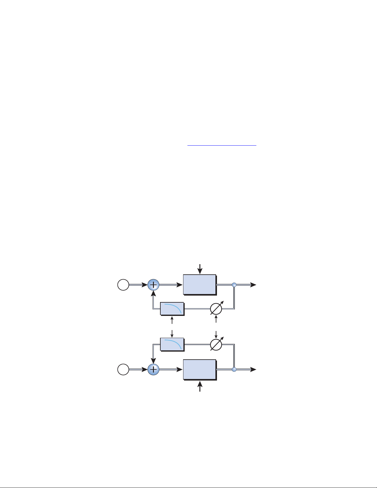
Delay
t
Background: Delay
A delay line makes a copy of the incoming audio, holds it in memory, then plays it
back after a predetermined time.
Long delays produce echoes, short delays can be used for doubling or slapback effects.
Very short delays can be used to produce resonant flanging and comb filter effects or
create monotone robotic-sounding effects (Hint: use feedback). Stereo signals are
summed together before entering a mono delay.
A feedback path recirculates the delayed audio back around through the delay line.
When creating echo effects, the feedback controls how many echoes will be produced.
With short delay settings, the feedback control acts as a resonance control, increasing
the amount of comb filtering produced by the delay line. See “
A Tone control in the feedback path cuts some of the high frequency energy each time
the audio goes through the delay line. This simulates the natural absorption of high
frequencies in a room and can also be used to simulate tape-based echo units.
The Wet/Dry mix controls how loud the echoes are in relation to the original signal.
This Delay is a true stereo delay line with completely independent left and right
channels right channels. This delay line features four different modes, which affect how
the signals are routed and cross coupled.
Flanger” on page 85.
5 - Effects
Effects Descriptions
Discrete stereo
Use this mode when you want to preserve the stereo image of the delayed signals. You
can also create panning effects by setting one delay long and the other short.
Delay Mode:
R Delay Time
Discrete stereo
The left and right
channels are kept
totally separate.
Right
In
Left
In
HF
Damp
HF
Damp
Right
Delay
Righ
Out
FeedbackHF Damping
Left
Out
Left
Delay
L Delay Time
E-MU Systems 79
Page 80
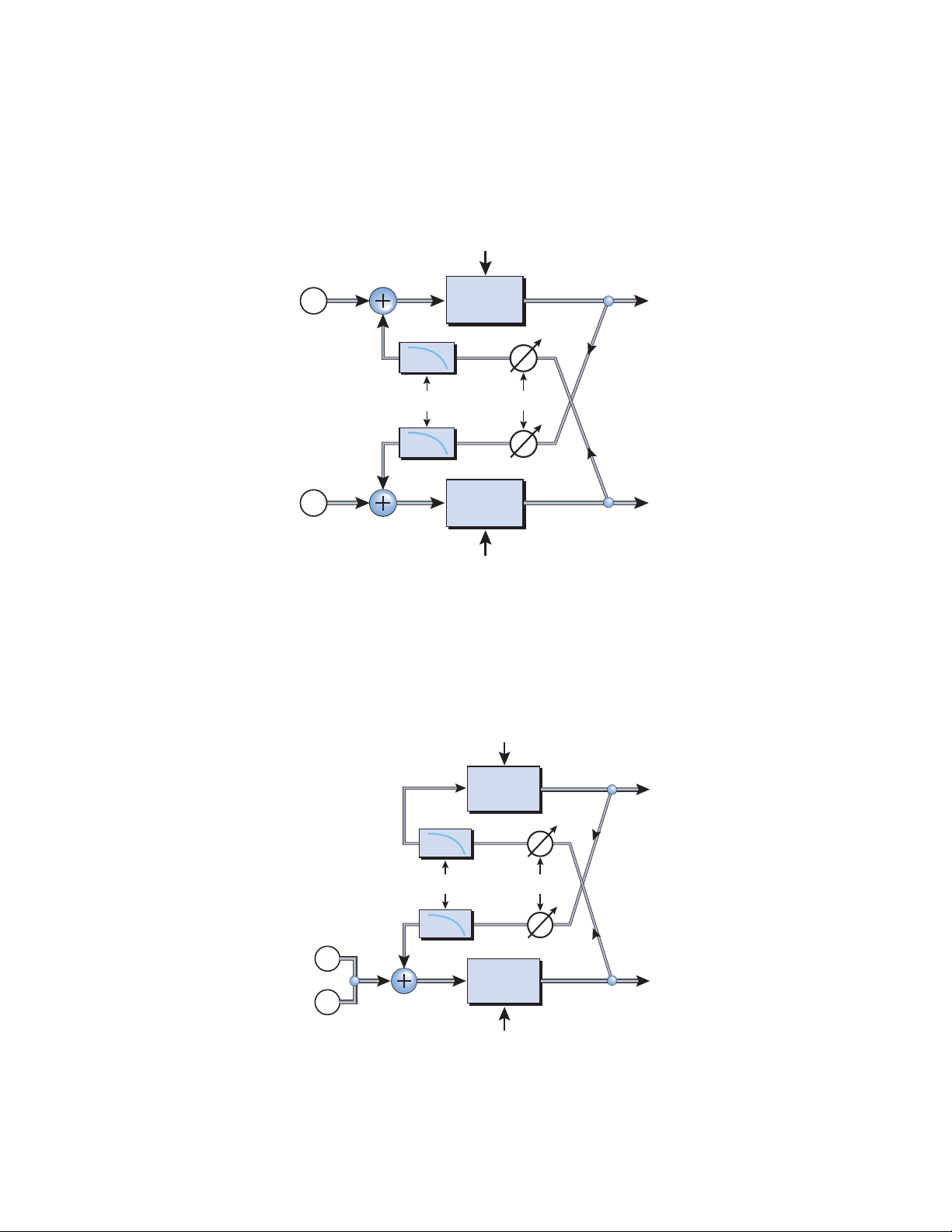
5 - Effects
t
t
Effects Descriptions
Ping Pong, stereo
This mode cross-couples the output of the left and right delay into the input of the
opposite channel. This mode works best with true stereo program material or with
completely different sounds on either channel.
Delay Mode:
R Delay Time
Ping Pong, stereo
HF
HF
Right
Delay
Righ
Out
Feedback
Left
Out
The output of the left
and right channels are
fed into the opposite
channel.
Right
In
Left
In
Damp
HF Damp
Damp
Left
Delay
L Delay Time
Ping Pong, mono L->R
This mode creates echoes which bounce back and forth from left to right using either a
mono or stereo source. This is the classic ping-pong echo effect.
Delay Mode:
Ping Pong, mono L->R
The input is summed to
mono, then fed into the
left channel. The output
of the left channel is
cross-coupled into the
right channel.
The right channel output
is cross-coupled into the left
channel input.
L In
R In
R Delay Time
HF
Damp
HF Damp
HF
Damp
Right
Delay
Righ
Out
Feedback
Left
Out
Left
Delay
L Delay Time
80 Proteus VX Operation Manual
Page 81
Parameter Description
Left Delay Time Sets the length of the delay for the left channel in milliseconds.
Range: .01 millisecond to 2000 milliseconds
(.01ms. minimum increment between settings)
Right Delay Time Sets the length of the delay for the right channel in milliseconds.
Range: .01 millisecond to 2000 milliseconds
(.01ms. minimum increment between settings)
Mode Changes the signal routing of the delay. The four modes are:
Discrete stereo - signal paths remain completely separate.
Ping Pong, stereo - The feedback paths feed the opposite
channel.
Ping Pong, mono L->R - The effected signal is summed to
mono, then fed down the left channel whose feedback path feeds
the right channel. The right channel feedback path feeds the left
channel.
Ping Pong, mono R->L - This is the same as the previous
algorithm except that the L-R channels are reversed.
Feedback Sets the amount of delayed signal that will be recirculated through
both delay lines. Range: 0% to 100%
HF Damping High Frequency Damping cuts the high frequency content in the
feedback paths. This causes the echoes to decay naturally away.
5 - Effects
Effects Descriptions
Modulation Parameters
• Wet/Dry Mix
• Feedback
E-MU Systems 81
Page 82
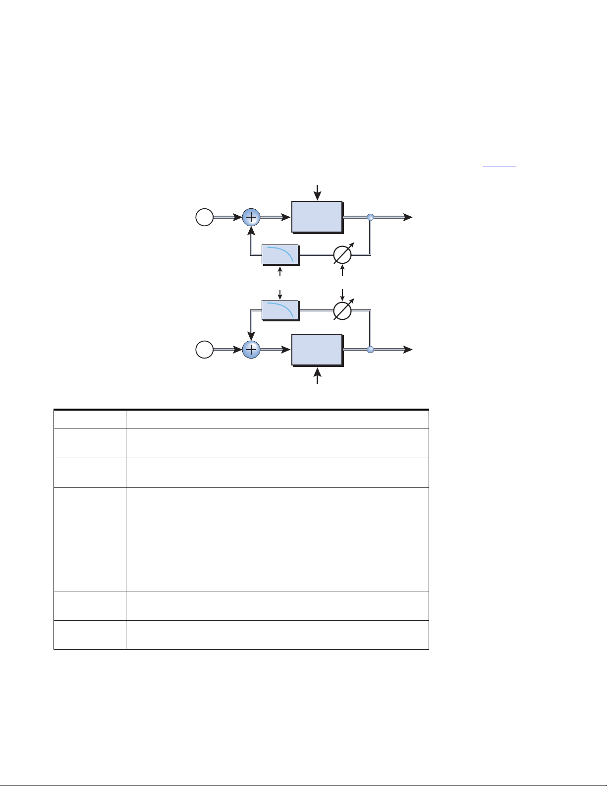
5 - Effects
t
Effects Descriptions
Delay (BPM)
The BPM Delay is similar to the Stereo Delay except that the delay time is synchronized
to the master (MIDI) clock in note divisions. This allows you to easily set up synchronized echoes to your beats. Because the left and right channels are completely
independent, you can set up different synchro-sonic patterns on each side. The four
modes are the same as the stereo delay.
Delay Mode:
R Delay Division
Discrete stereo
HF
Right
Delay
Righ
Out
The left and right
channels are kept
totally separate.
Right
In
Damp
See page 79 for full
descriptions and
diagrams.
Feedback
Left
Out
Left
In
HF Damp
HF
Damp
Left
Delay
L Delay Division
Parameter Description
Left Delay
Division
Right Delay
Division
Mode Changes the signal routing of the delay. The four modes are:
Feedback Sets the amount of delayed signal that will be recirculated through
HF Damping High Frequency Damping cuts the high frequency content in the
Sets the length of the delay for the left channel in milliseconds.
Range: 4/1 note to 1/64 dotted-note
Sets the length of the delay for the right channel in milliseconds.
Range: 4/1 note to 1/64 dotted-note
Discrete stereo - signal paths remain completely separate.
Ping Pong, stereo - The feedback paths feed the opposite channel.
Ping Pong, mono L->R - The effected signal is summed to mono,
then fed down the left channel whose feedback path feeds the right
channel. The right channel feedback path feeds the left channel.
Ping Pong, mono R->L - This is the same as the previous algorithm
except that the L-R channels are reversed.
both delay lines. Range: 0% to 100%
feedback paths. This causes the echoes to decay naturally away
Modulation Parameters
• Wet/Dry Mix
• Left Delay Division (Changes the division by a power of 2, up or down.)
• Right Delay Division (Changes the division by a power of 2, up or down.)
• Feedback
82 Proteus VX Operation Manual
Page 83
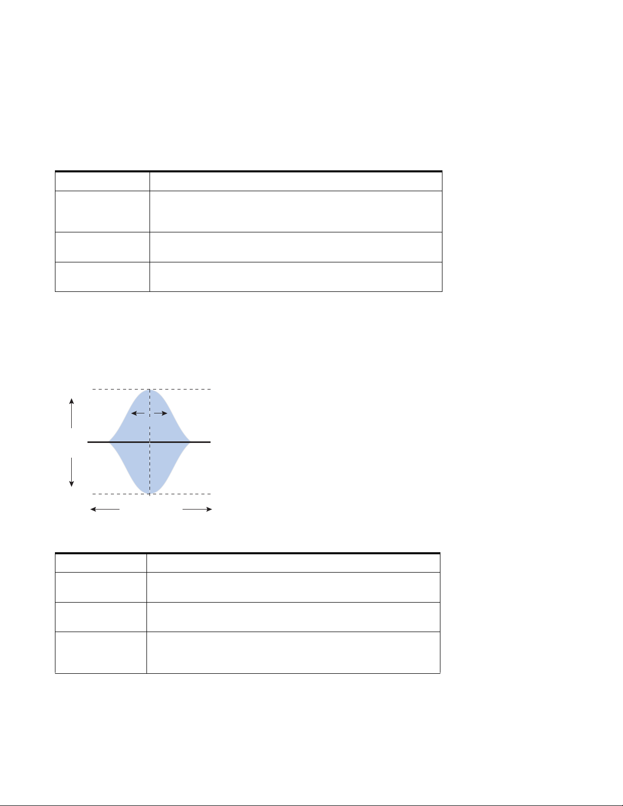
Early Reflections
Early reflections are the initial echoes that you hear when listening to sound in an
indoor space. The echoes are staggered because they are reflected off surfaces which are
at various distances from your ear. Normally this effect would be part of a reverb
algorithm, but we decided to include it as a separate effect because it creates useful and
interesting sounds.
Parameter Description
E.R. Mode Selects the pattern of the early reflections. Select between:
Hall 1, Hall 2, Hall 3, Room, Spiral, Multitap, 6 tap, 12 tap,
12 tap rising, up & down.
Room Size Changes the spacing of the early reflections characteristics of
various room sizes and shapes.
L/R Offset Scales the spacing of left side reflections versus the right side, to
create a more interesting stereo image. Range: -50% to +50%
Modulation Parameters
• Wet/Dry Mix
5 - Effects
Effects Descriptions
1-Band Para EQ
+15dB
Boost
Width
+
Gain
-
Cut
-15dB
Center
Frequency
Parameter Description
Gain Sets the amount of cut (-) or boost (+) of the selected frequency
band. Range: -24dB to +15dB
Center Frequency Sets the range of frequencies to be cut or boosted with the Gain
control. Range: 40Hz to 16kHz
Bandwidth Sets the width of the frequency range for the Center Frequency
band that will be cut or boosted by the Gain control.
Range: .01 octave to 2 octaves
This single band parametric equalizer is useful
when you just want to boost or cut a single
range of frequencies. For example, if you just
want to brighten up the lead vocal a bit, you
might choose this EQ. This EQ offers up to
+15dB boost and -24dB of cut.
Modulation Parameters
•Gain
• Frequency
•Bandwidth
E-MU Systems 83
Tip - EQ becomes a
powerful performance
tool when the
modulation parameters
are patched to MIDI
Controllers.
Page 84
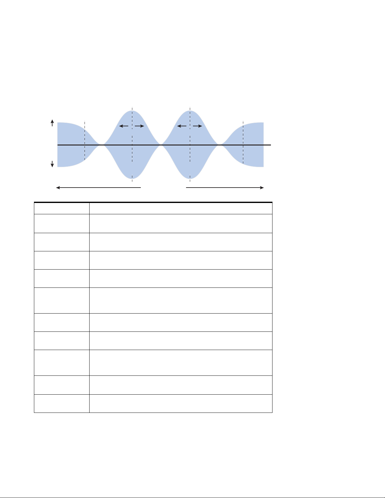
5 - Effects
Effects Descriptions
4-Band EQ
This 4-band equalizer provides two shelving filters at the high and low ends of the
frequency range and two fully parametric bands in the center. Up to +15 dB of boost
and -24dB of cut is provided for each band.
Low-Shelf
+
Boost
Gain
-
Cut
Low Mid
Band
Corner
Frequency
Width
Center
Frequency
Frequency
High Mid
Band
Width
Center
Frequency
High-Shelf
Corner
Frequency
Note: The Wet/Dry
Mix control on an
equalizer should normally
be set to 100% wet or
unpredictable results may
occur.
Parameter Description
High Gain Sets the amount of cut (-) or boost (+) of the high frequency shelf.
Range: -24dB to +15dB
High
Frequency
High Mid Gain Sets the amount of cut (-) or boost (+) of the High Mid Frequency
High Mid
Frequency
High Mid
Bandwidth
Low Mid Gain Sets the amount of cut (-) or boost (+) of the Mid 1 Frequency
Low Mid
Center Freq.
Low Mid
Bandwidth
Low Gain Sets the amount of cut (-) or boost (+) of the low frequency shelf.
Low
Frequency
Sets the corner frequency where the signal begins getting cut or
boosted with the High Gain control. Range: 4kHz to 16kHz
band. Range: -24dB to +15dB
Sets the range of frequencies to be cut or boosted with the High
Mid Gain control. Range: 1kHz to 8kHz
Sets the width of the frequency range for the High Mid Center
Frequency band that will be cut or boosted by the High Mid Gain
control. Range: .01 octave to 2 octaves
band. Range: -24dB to +15dB
Sets the range of frequencies to be cut or boosted with the Mid 1
Gain control. Range: 200Hz to 3kHz
Sets the width of the frequency range for the Low Mid Center
Frequency band that will be cut or boosted by the Low Mid Gain
control. Range: .01 octave to 2 octaves
Range: -24dB to +15dB
Sets the corner frequency where the signal begins getting cut or
boosted with the Low Gain control. Range: 40Hz to 800Hz
Tip: When using a
MIDI controller to change
the EQ gain, a value of
77 = 0dB.
Modulation Parameters
•High Gain
• High Mid Gain
•Low Mid Gain
•Low Gain
84 Proteus VX Operation Manual
Page 85
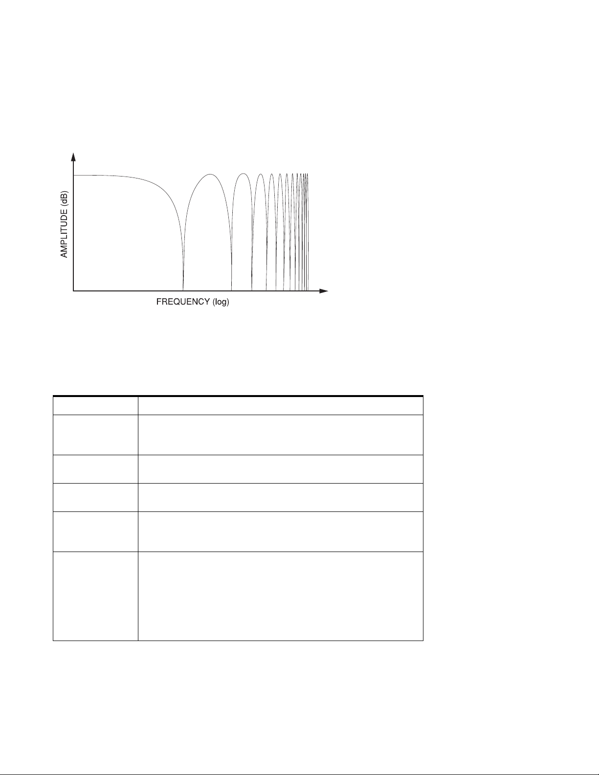
Flanger
A flanger is a very short delay line whose output is mixed back together with the
original sound. Mixing the original and delayed signals results in multiple frequency
cancellations known as a comb filter. Since the flanger is a type of filter, it works best
with harmonically rich sounds.
5 - Effects
Effects Descriptions
In order to hear a rich
flanging effect, the
original signal must be
mixed in with the flanged
signal. This can be
accomplished using the
Wet/Dry Mix control or
with the Main Send
(when using Aux effects).
A low frequency oscillator is included to slowly change the delay time. This creates a
rich, sweeping effect as the notches move up and down across the frequency range. The
amount of feedback deepens the notches, intensifying the effect. You can invert the
feedback signal by choosing a negative feedback value. Inverting the feedback signal
creates peaks in the notch filter and deepens the effect.
Parameter Description
Initial Delay Sets the initial delay of the flanger in .01 millisecond increments.
This parameter allows you to “tune” the flanger to a specific
frequency range. Range: .01ms to 4ms
Depth Sets how much the LFO affects the delay time. Increases the
animation and amount of the flanging effect. Range 05 to 100%
Rate Sets the speed of the low frequency oscillator which modulates the
delay time of the flanger. Range: .01 Hz to 20Hz
Feedback Controls how much signal is recirculated through the delay line
and increases resonance. Negative values can produce intense
flanging with some signals. Range 0% to 100%
Through Zero On - Adds a short delay to the original signal to simulate the
classic “through-zero” flanger sound, which was originally created
using two tape recorders.
On (out of phase) - Inverts the phase (180°) and adds a delay
to the original signal producing additional phase cancellation.
If the feedback control is set to zero, complete cancellation occurs
when the flanger goes through zero
Modulation Parameters
• Wet/Dry Mix
•Depth (Mod)
• Rate (Mod)
• Feedback
E-MU Systems 85
Page 86
5 - Effects
Effects Descriptions
Growl
This is a new kind of self-modulation effect created especially for the Proteus VX. Growl
excels at turning simple sounds into musically complex and interesting ones.
Depending on the input wave and control settings, Growl can impart a horn-like
quality, a warm tube distortion, or a harsh rasp.
Growl is easy to use. Just turn up the depth control and wet/dry mix, then adjust the
Initial control until you find the right amount of “growl”. Then, back off the other
controls and a fine tune all the other controls to taste. It’s Grrrreat!
Parameter Description
Initial This control “Tunes” the effect to a specific frequency range.
Range: .01ms to 15ms
Depth Sets how much self modulation is applied. Range 0% to 100%
Color Controls the tonal color of the effect. Range: -99% to +99%
Pre-Filter Anti-aliasing filter. Turn this filter up if you hear aliasing at high-
frequencies.
Modulation Parameters
• Wet/Dry Mix
•Depth
• Color
86 Proteus VX Operation Manual
Page 87
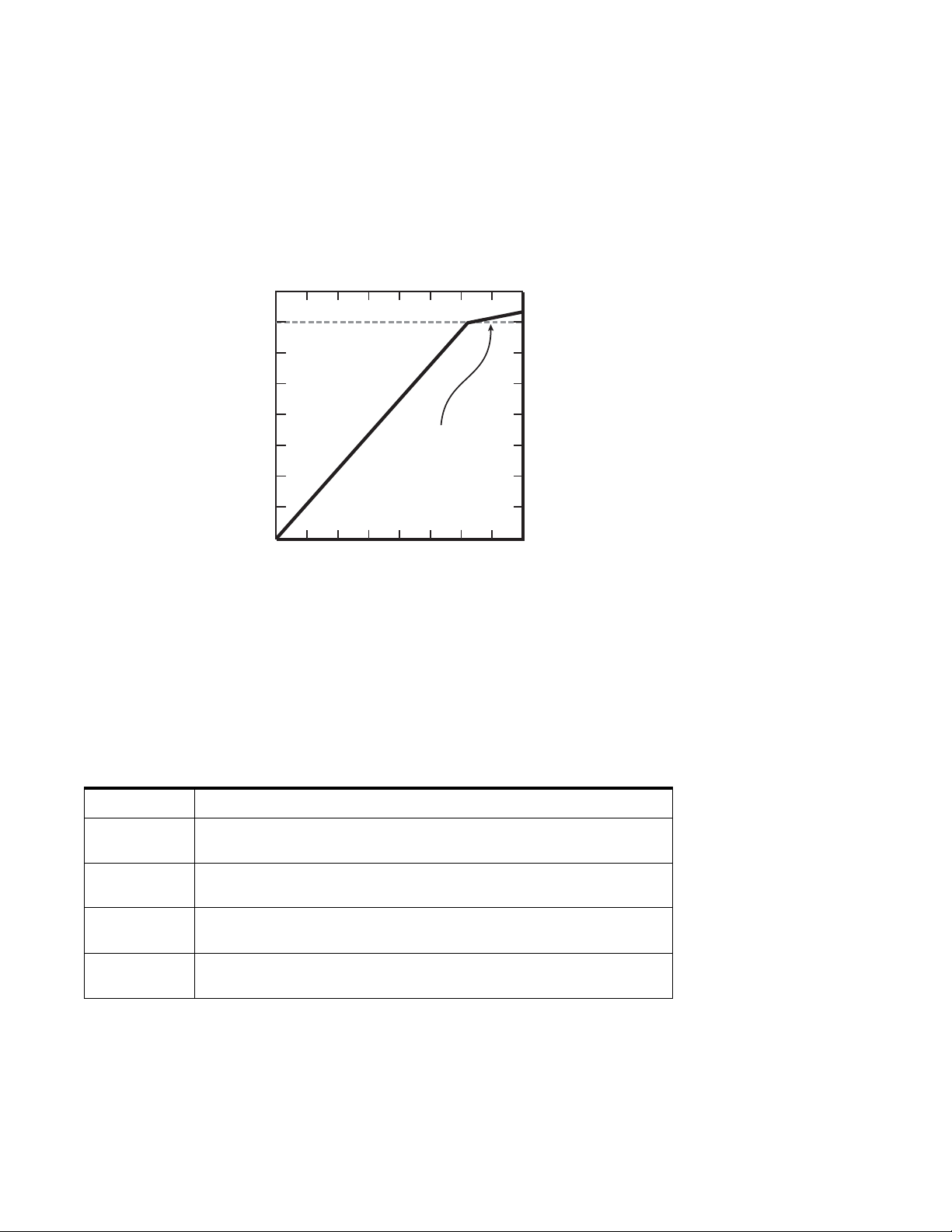
Limiter
The Limiter sets a “maximum level” on the audio. Beyond this Threshold, any increase
in gain is effectively prevented or limited, hence the name. A limiter works like a
compressor with a very high ratio setting.
The limiter is particularly useful for taming the highly resonant peaks that can be
produced by the Z-plane filters. Set a fast attack time to suppress transients and use the
Release control to reduce “pumping” effects.
0dB
5 - Effects
Effects Descriptions
-10dB
Threshold: -10dB
Signals above the
Threshold level are
prevented from
getting any louder.
-80dB
The Output Gain control amplifies the signal after it has been limited to bring it back up
in volume. If you don’t increase the gain, the signal may be lower in volume.
Two other controls are Attack and Release. Attack controls how quickly the gain is
turned down after the signal exceeds the threshold. Release controls how fast the gain
is returned to its normal setting after the signal has fallen below the threshold again.
Longer release times are generally used to reduce the so called “pumping” effect as the
compressor turns on and off. Don’t make the release time too long, however, or the
compressor won’t have time to recover for the next pluck or hit. In general, the attack
and release controls are used to smooth out the action of the limiter, but they can also
be used to create special effects.
Parameter Description
Threshold Threshold sets the “trigger” level for limiting. Signal levels above the
threshold will be brought down in volume. Range: -50dB to +20dB
Output Gain Amplifies the signal after it has been compressed to bring up the
volume. Range: -24dB to +12dB
Attack TIme Controls how quickly the gain is turned down after the signal exceeds
the threshold. Range: 1 ms to 200 ms.
Release Time Controls how fast the gain is returned to its normal setting after the
signal has fallen below the threshold. Range: 0.2 second to 1 second
Modulation Parameters
•None
E-MU Systems 87
Page 88
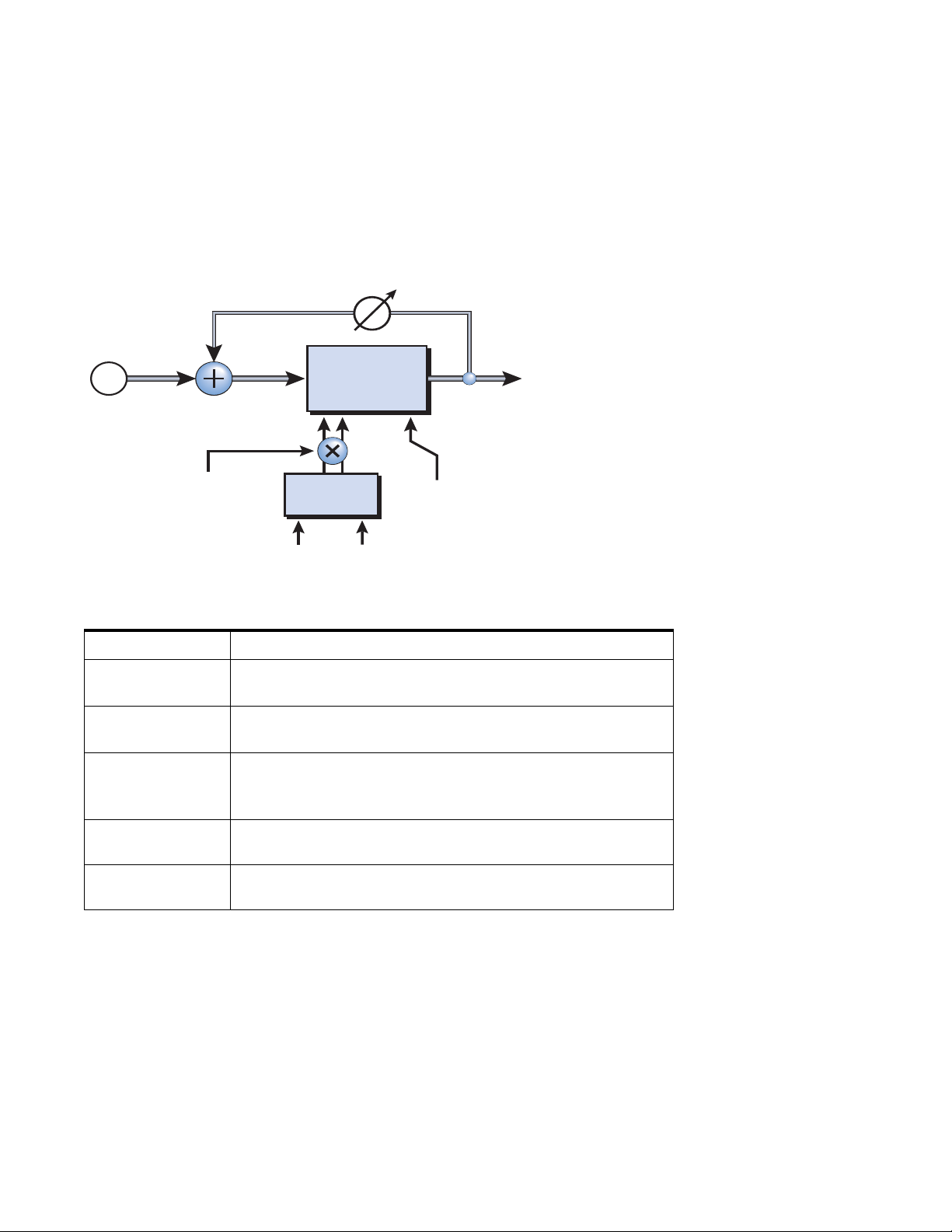
5 - Effects
Effects Descriptions
Phaser
A Phaser (or phase shifter) produces a fixed number of peaks and notches in the audio
spectrum which can be swept up and down in frequency with a low frequency oscillator (LFO). This creates a swirly, ethereal sound with harmonically rich sound sources
of a type of pitch shift with simpler sounds. The phase shifter was invented in the
1970’s and the characteristic sound of this device evokes emotions of that musical era.
Feedback
In
Phaser
(stereo)
Signal path = Stereo
Out
Depth
LFO
Rate
L/R
Stages
Phase
Parameter Description
Depth Controls how much the Center Frequency is swept by the LFO.
Range: 0% to 100%
Rate Controls the sweep rate of the Low Frequency Oscillator.
Range: .01Hz to 20Hz
Feedback Increases the depth of the notches and height of the peaks.
Inverted values invert the feedback polarity.
Range: -100% to +100%.
Stages Selects between: 3, 6, 9, or 12 phase shift stages and thus the
number of peaks and notches in the frequency response.
LFO L/R Phase Offsets the LFO between the left and right phaser channels.
(0°, 90°, or 180°). This adds animation to the sound.
Modulation Parameters
• Wet/Dry Mix
• Depth (Modulation)
• Rate (Modulation)
• Feedback
88 Proteus VX Operation Manual
Page 89
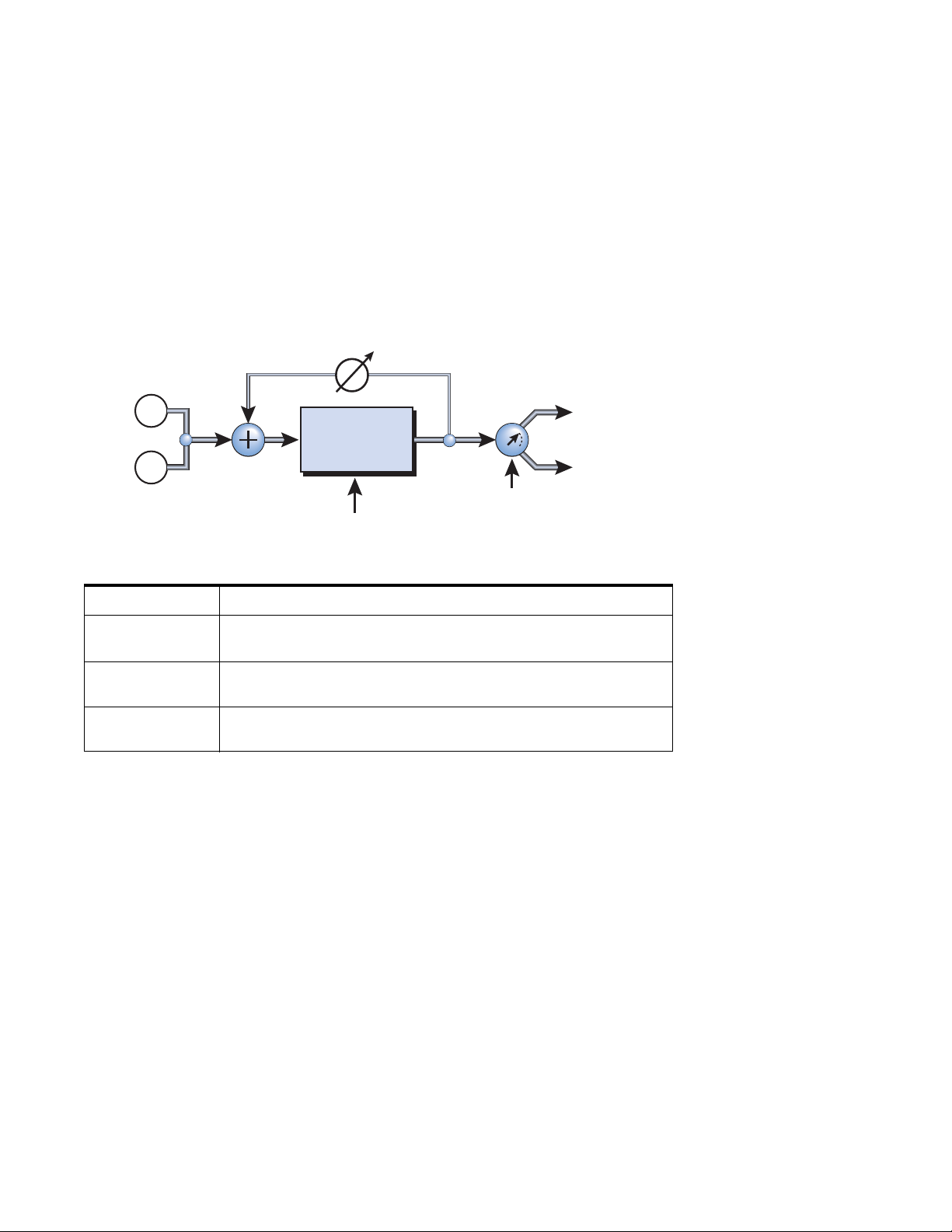
Pitch Shifter (mono)
t
The pitch shifter (also known as a “harmonizer”) shifts the pitch of the input up or
down while preserving the time between events. (Unlike speeding up or slowing down
a tape recorder or pitch shifting across the Proteus VX keyboard.) The range of the pitch
shifter is -36 semitones down to +24 semitones up in .01 semitone increments.
Small amounts of pitch shifting makes an effective type of chorus. Semitone shifts
work especially well on the human voice for harmonization and for special effects.
With the Feedback control turned up, the pitch shifted (and slightly delayed) signal
will be recirculated through the pitch shifter and re-shifted further up or down.
Feedback
5 - Effects
Effects Descriptions
L In
L Out
Pitch
R In
Parameter Description
Pitch Shift This control selects the pitch shift interval.
Range: -36 semitones to +24 semitones
Feedback Controls how much signal is recirculated through the pitch shifter.
Range 0% to 100%
Pan This parameter moves the pitch shifted sound left or right. This
moves the apparent sound source left or right.
Modulation Parameters
• Wet/Dry Mix
•Pitch
• Feedback
•Pan
Shifter
R Ou
Pan
Pitch Shift
E-MU Systems 89
Page 90
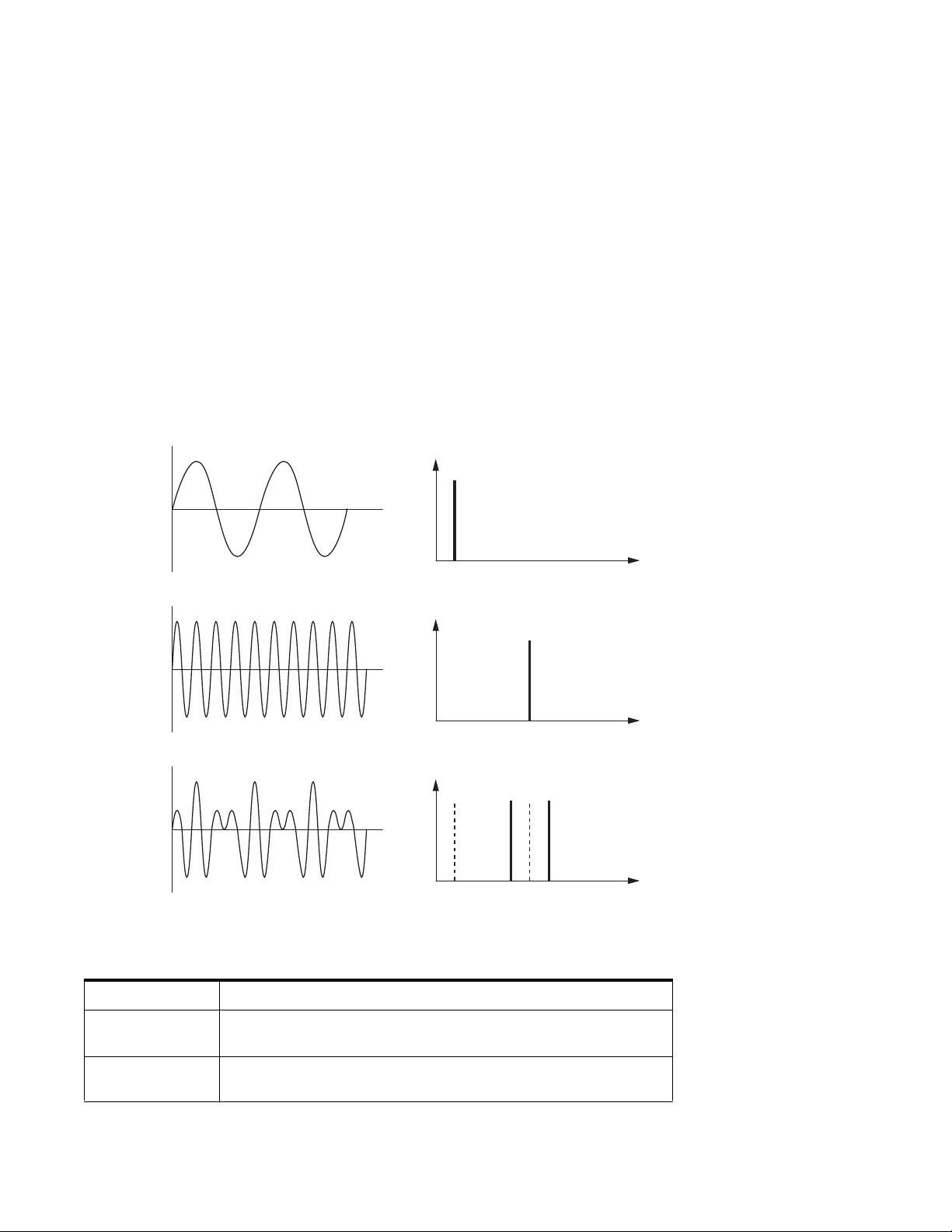
5 - Effects
Effects Descriptions
Ring Modulator
A ring modulator takes two signals and multiplies them together to produce an output
signal containing only the sum and difference frequencies of the two input waves. The
original frequencies are not output. If complex waveforms are used, every harmonic of
each signal multiplies every other according to its amplitude. Because ring modulation
is a linear process, these new sum and difference frequencies are displaced from their
normal exponential harmonic relationship. As a result, ring modulators tend to create
clangorous, bell-like timbres.
In this ring modulator, each side of the stereo input source is multiplied by an internal
sine wave oscillator. The internal oscillator can remain at a fixed pitch or it can be
modulated by an envelope follower.
The envelope follower sweeps the pitch of the modulating oscillator up or down based
on the amplitude of the input signal. Try adjusting the Proteus VX attack and decay
controls (amp) to hear the effect of the envelope follower. The envelope follower can
sweep the modulating oscillator in either the positive or negative direction by setting
the value positive or negative.
Input 1
200 Hz
AMPLITUDE
200
FREQUENCY (Hz)
Input 2
800 Hz
AMPLITUDE
800
FREQUENCY (Hz)
Result
600 &
1000 Hz
his diagram shows the result of Ring Modulating two sine waves with frequencies of 200 Hz
800 Hz. Only the Sum and Difference frequencies of 600 Hz and 1000 Hz will be output.
Parameter Description
Frequency This control sets the frequency of the modulation waveform
Range: 0 Hz to 5000 Hz
Envelope Follower Controls how much the amplitude envelope sweeps the
modulating oscillator. Range: -10x to +10x
AMPLITUDE
200 600 800 1000
FREQUENCY (Hz)
90 Proteus VX Operation Manual
Page 91
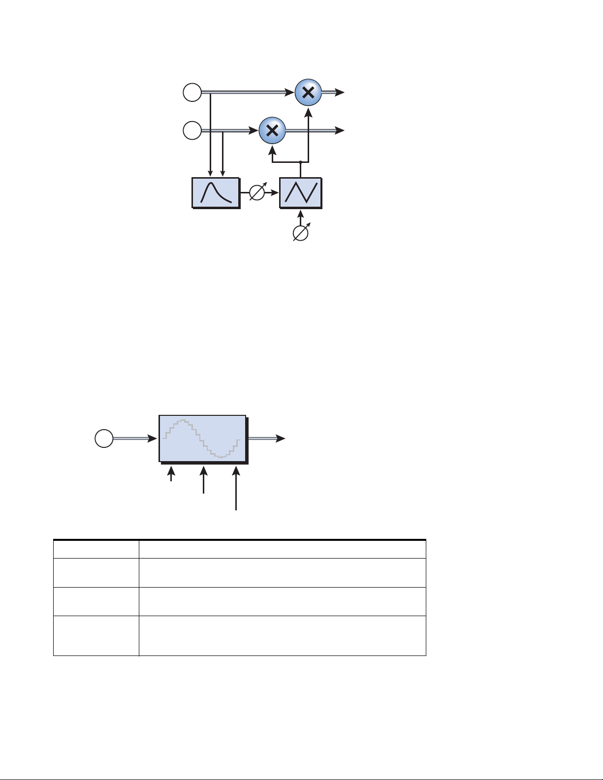
5 - Effects
t
Effects Descriptions
R OutR In
Ring
L In
L Out
Modulator
Modulating
Oscillator
Envelope
Follower
Modulation Parameters
• Wet/Dry Mix
• Frequency
• Envelope Amount
SP12-ulator
The E-MU SP-12 Sampling Drum Machine was the most advanced beat box of its day
and remains a classic. The SP-12 used a gritty, “drop-sample” pitch shifting technique
which contributed to its distinctive sound. The SP12-ulator effect pays homage to the
venerable SP-12, and allows you to mangle sounds as your forefathers did many years
ago.
Freq.
In
Signal path = Stereo
SP12-ulator
Ou
Freq.
Depth
Resolution
Parameter Description
Frequency This parameter controls the number of samples that will be
“dropped.” Range: 0 - 100
Depth This parameter controls the intensity of the resultant distortion.
Range: 0% to 100%
Resolution The SP-12 is a 12-bit drum machine. The SP12-ulator allows you to
reduce the bit depth to 12-bits, or all the way down to 1-bit
resolution if you must. Range: Hi-Res (32 bit), 12-bit to 1-bit
Modulation Parameters
• Wet/Dry Mix
• Frequency
•Depth
E-MU Systems 91
Page 92
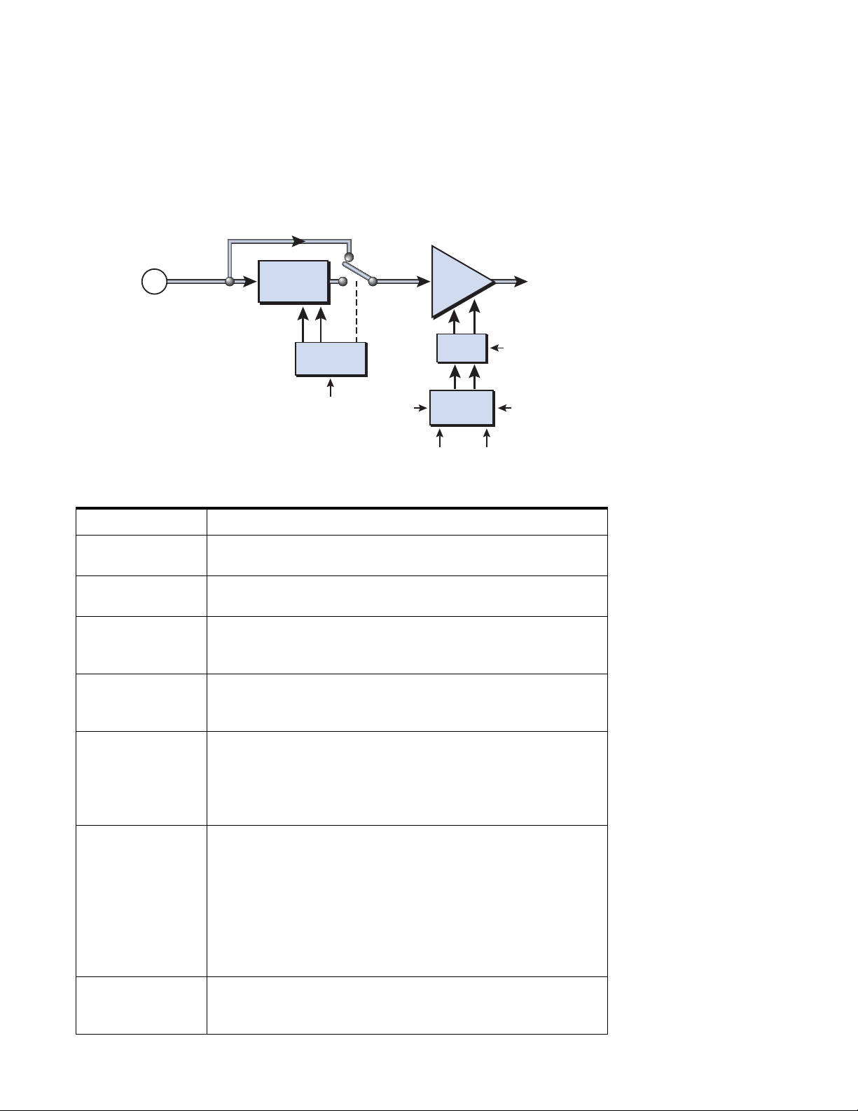
5 - Effects
t
Effects Descriptions
Tremulator BPM
Tremolo is amplitude modulation and is also a standard guitar amp effect. The Tremulator BPM is more like a tremolo on steroids! In addition to the standard rate and
amount controls, the Tremulator lets you beat-sync the tremolo speed to the song
tempo, has eight different modulation waveforms with adjustable lag, lets you autopan
the stereo signal in several ways, and even includes a sweepable lowpass filter with five
modes.
In
Stereo
c
F
Q
Mode
Mode
TremFilter
L
Note
Lag
LFO
Ou
R
Lag
PhaseSync
Wave
Duration
Parameter Description
Wet/Dry Controls the intensity (depth) of the tremolo effect.
Range: 0% to 100%
LFO Note Duration The speed of the LFO is locked to a note division of the master
tempo. Range: 4/1 note to 1/64 dotted-note
LFO Waveshape Selects between the following modulation waveforms:
Sine, Triangle, Half Sine, Sawtooth Up, Sawtooth Down, Square,
Pulse 25, Pulse 75
Lag Sets the slew rate of the LFO output. This is normally used to
round the corners of the square waves, but can create interesting
effects with the other waveforms as well. Range: 0% to 100%
L/R Phase Offsets the LFO phase between the left and right channels.
(0°, 90°, 180°, 270°).
0° - Both the left and right channels are the same.
180° - Creates a back and forth, “ping-pong” effect.
90°/270° - Creates a rotating effect.
Mode Six different modes are available:
Tremolo - Tremolo amplitude modulation only
Tremolo + Filter 1 - Tremolo & 2-pole filter sweep, no Q
Tremolo + Filter 2 - Tremolo & 2-pole filter sweep, Mid Q
Filter 3 - 2-pole filter sweep, Low Q
Filter 4 - 2-pole filter sweep, Mid Q
Filter 5 - 2-pole filter sweep, High Q
Note: The initial filter frequency is set lower as the Q is increased.
Sync (LFO Phase) Re-syncs the LFO (to the peak of the wave) whenever this button
is pressed or whenever the sync modulation input goes from zero
to a positive value. You could connect a footswitch.
92 Proteus VX Operation Manual
Page 93

Tre mula tor Wa v efo r ms
5 - Effects
Effects Descriptions
Triangle
Sawtooth
Sine
Square
Down
Modulation Parameters
• Wet/Dry Mix
• Rate (LFO Note Duration)
• Waveshape
•Sync
Half
Sine
Pulse
75
Sawtooth
Up
Pulse
25
E-MU Systems 93
Page 94
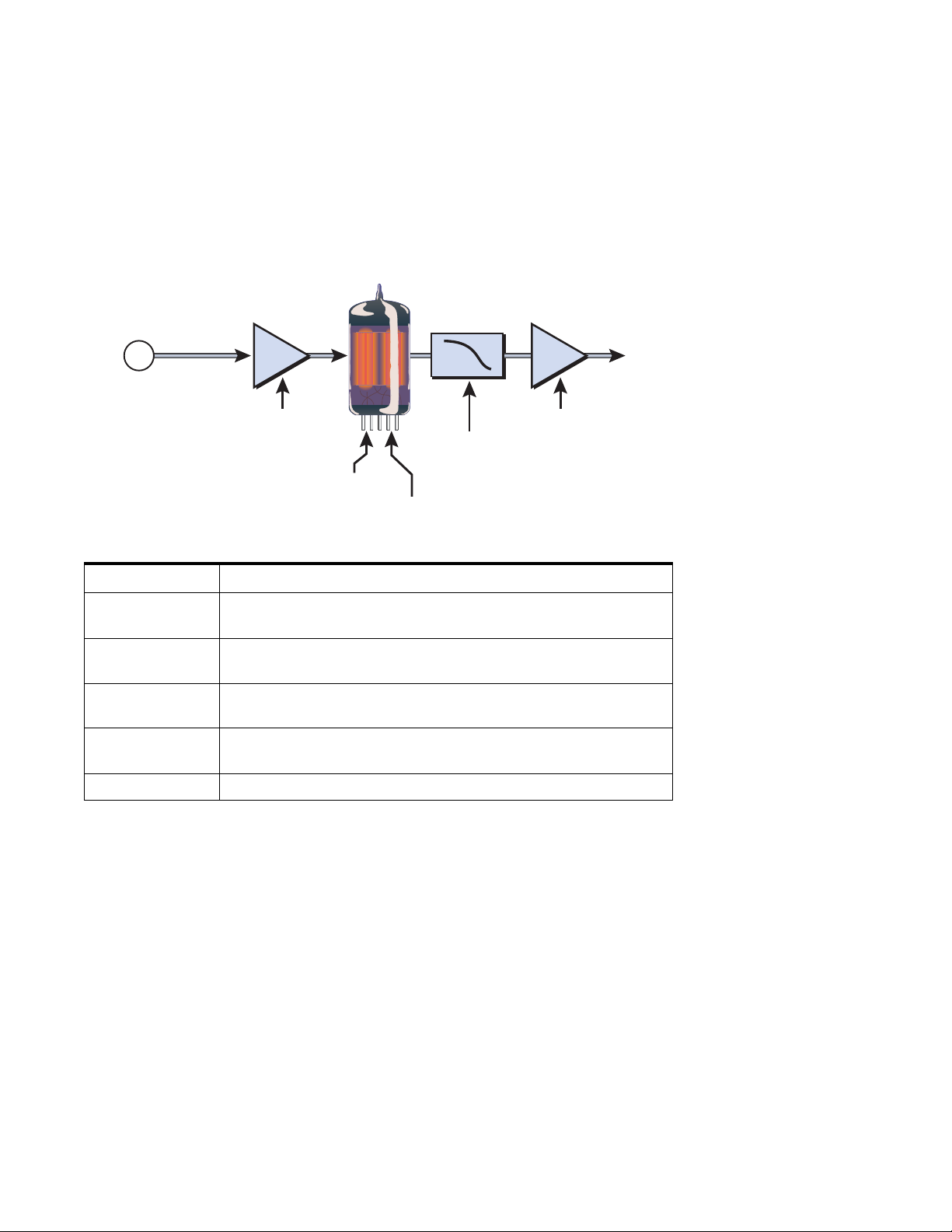
5 - Effects
86$
$;
$86$
Effects Descriptions
Tube
The Tube is a tube amplifier simulator based on “soft clipping”. An overdriven tube
amplifier sounds good because it generates even harmonic distortion products. This
digital tube gently rounds the waveform in a smooth, controlled manner much like a
real vacuum tube. Set the amount of distortion using the Gain control, then adjust the
tone using the Treble and Bias controls. The Compression control smooths out volume
changes and the Output Level control sets the final volume of the effect.
Lowpass
$;
Filter
In
Signal path = Stereo
Gain
86 $
Presence
Output
Level
Out
Bias
Compression
Parameter Description
Gain This parameter controls the overdrive amount on the “tube” and
thus, the amount of distortion generated. Range: 0.25 - 50.00
Output Level This parameter sets the output volume level and has no effect on
the tone.
Presence This control sets the lowpass filter frequency at the output of the
“tube”.
Compression Tubes have a certain amount of natural “soft” compression. This
controls how much compression is applied.
Bias Bias controls at what point in the waveform clipping begins.
Modulation Parameters
• Wet/Dry Mix
•Gain
•Output Level
94 Proteus VX Operation Manual
Page 95
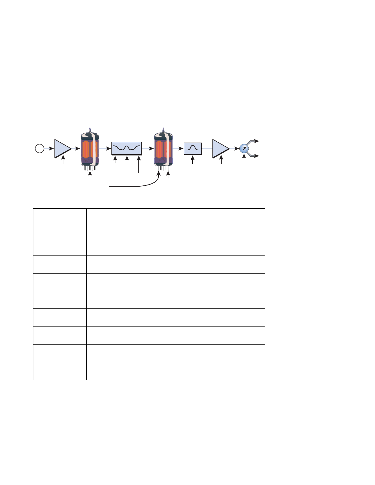
Twin
86$
$;
$86$
86$
$;
$86$
The Twin utilizes two “tube” stages to simulate the overdrive response of a guitar
amplifier. Separate gain controls allow you to precisely control the amount of soft
clipping from each “tube” stage. A three-band tone control between the two stages and
a presence control after the 2nd stage allow you to precisely contour the overdrive
frequencies. Set the amount of distortion using the Volume and 2nd Stage Gain
controls, then adjust the tone using the Treble, Mid and Bass controls. The
Compression control smooths out the timbrel changes and the Output Level control
sets the final volume of the effect.
5 - Effects
Effects Descriptions
Presence
Filter
Presence
Master
Volume
Out
Pan
In
Volume
$;
86 $
Compression
Controls
Bass
Tone
Mid
Treble
$;
86 $
2nd
Stage Gain
Parameter Description
Volume This parameter controls the overdrive amount on the 1st “tube”
and thus the amount of distortion generated.
Master Volume This parameter sets the output volume level and has no effect on
the tone.
Treble Allows you to adjust the high frequency content between the two
“tubes”.
Mid Allows you to adjust the mid frequency content between the two
“tubes”.
Bass Allows you to adjust the low frequency content between the two
“tubes”.
2nd Stage Gain This parameter controls the overdrive amount on the 2nd “tube”
and thus, the amount of distortion generated.
L
R
Presence Allows you to adjust the mid frequency content at the output of
the 2nd “tube”.
Pan Sets the left/right pan position of the processed sound.
Range: -100% to +100%
Compression Tubes have a certain amount of natural “soft” compression. This
controls how much compression is applied by both tubes.
Modulation Parameters
• Wet/Dry Mix
•Gains 1 & 2
•Master Volume
•Pan
E-MU Systems 95
Page 96

5 - Effects
Effects Descriptions
96 Proteus VX Operation Manual
Page 97
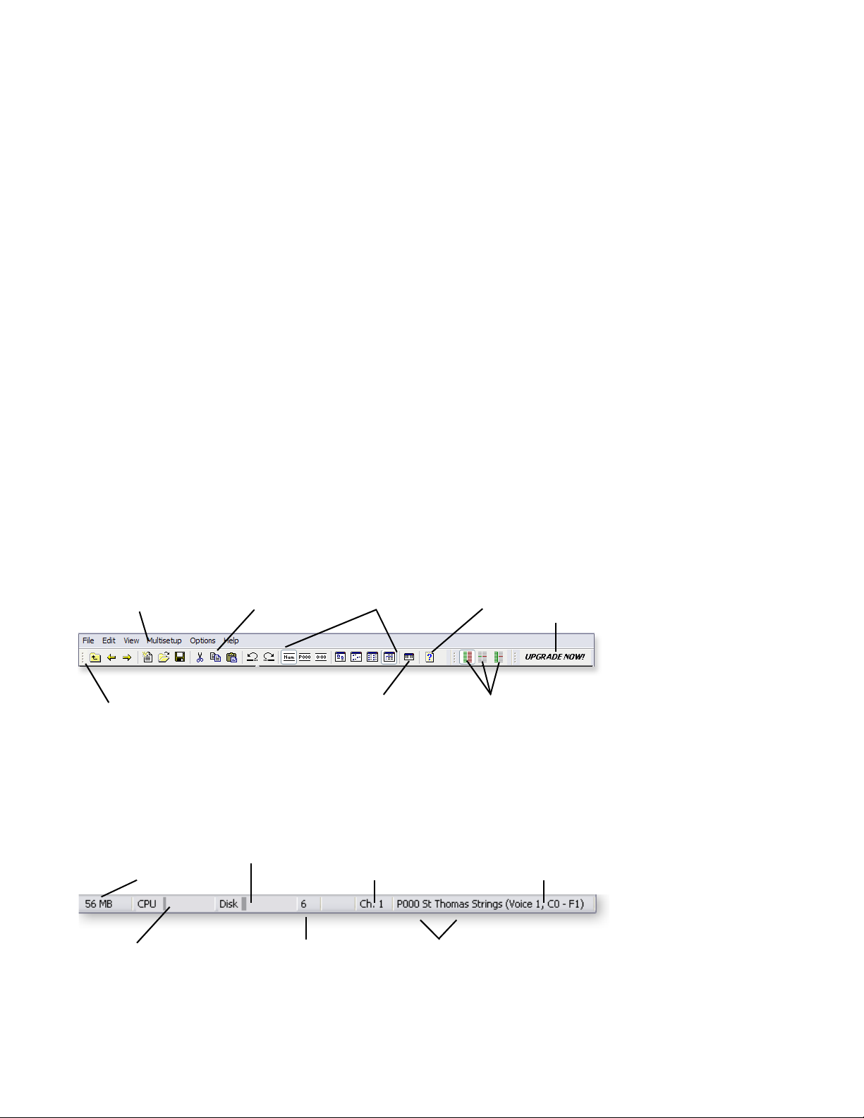
6 - Controls
This chapter describes how to operate the controls of the Proteus VX. There are certain
tips and tricks to learn in becoming a power user, and a good number of them are in
this chapter.
The Toolbars
The toolbars are located just beneath the menu bar at the top of the window and one
more at the very bottom of the window (the status toolbar). The toolbars provide
handy single-click buttons for the most common operations. By holding the mouse
pointer over the tool, a label will appear revealing the purpose of each tool.
The Status Toolbar is always located at the very bottom of the window and provides
context sensitive information, such as the current MIDI channel, preset name &
number, as well as the number of samples currently playing.
6 - Controls
The Toolbars
Menu Toolbars
Menu Bar
Toolbar
Handle
Status Toolbar
Pre-Roll Samples
in RAM
CPU Usage
Standard Tools
Disk Usage
Number of
Samples Playing
Display Modes Help
Mini Keyboard
Current
MIDI Channel
Preset Name
& Number
MIDI Modes
Upgrade
Information
Current Voice
& KYBD Range
E-MU Systems 97
Page 98
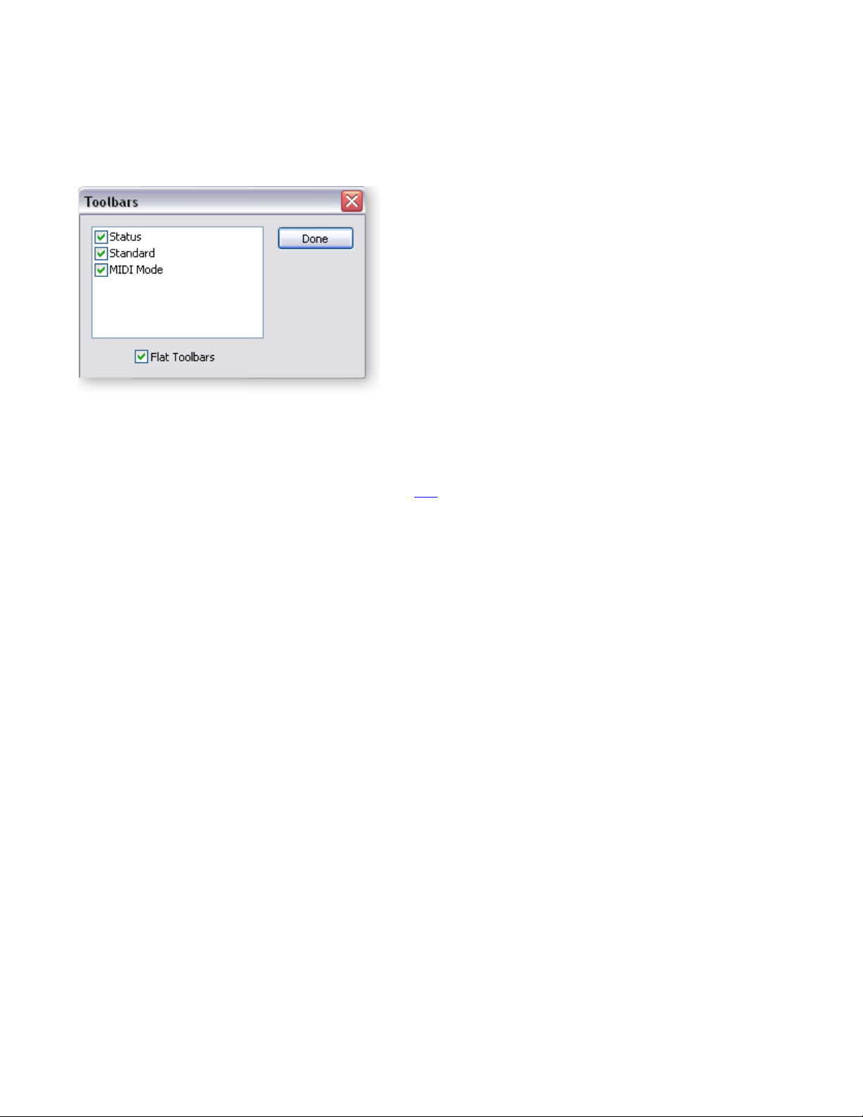
6 - Controls
Drag & Drop
Viewing and Hiding the Toolbars
Select Toolbars from the View menu to call up the Show/Hide Toolbar menu. Check
the boxes of the toolbars you wish to view. “Flat Toolbars” changes the look of the
toolbars.
Drag & Drop
You can use simple “Drag & Drop” operations for many Proteus VX functions. For
example, to copy a voice to another preset, simply left-click on the voice icon, then drag
it on top of another preset and release the mouse. Page 122
of the drag & drop functions.
provides a complete listing
Changing Settings
Entering Numeric Values
Numeric values are displayed in alphanumeric readouts with either an associated
control knob or an up/down button adjoining the display.
Numeric values can be changed by:
• Tu r n ing th e k nob (if there is one).
• Pressing the Up/Down keys when the cursor is over a field.
• Typing the desired value into the field.
Move the Cursor from the Keyboard
•Press the Tab key to move the cursor to the next field.
•Press Shift+Tab to move the cursor to the previous field.
Select the Knob or Slider and then:
•Use the Left/Right keys to increment or decrement the value by 1.
•Use the Page Up & Page Down keys increment or decrement by 10.
•Use the Wheel on a wheel-type mouse to increment or decrement the value.
•Press the Home key to turn the control all the way down.
•Press the End key to turn the control all the way up.
•Press the 5 key in the numeric keypad to center the control. (Num Lock must
be off)
98 Proteus VX Operation Manual
Page 99
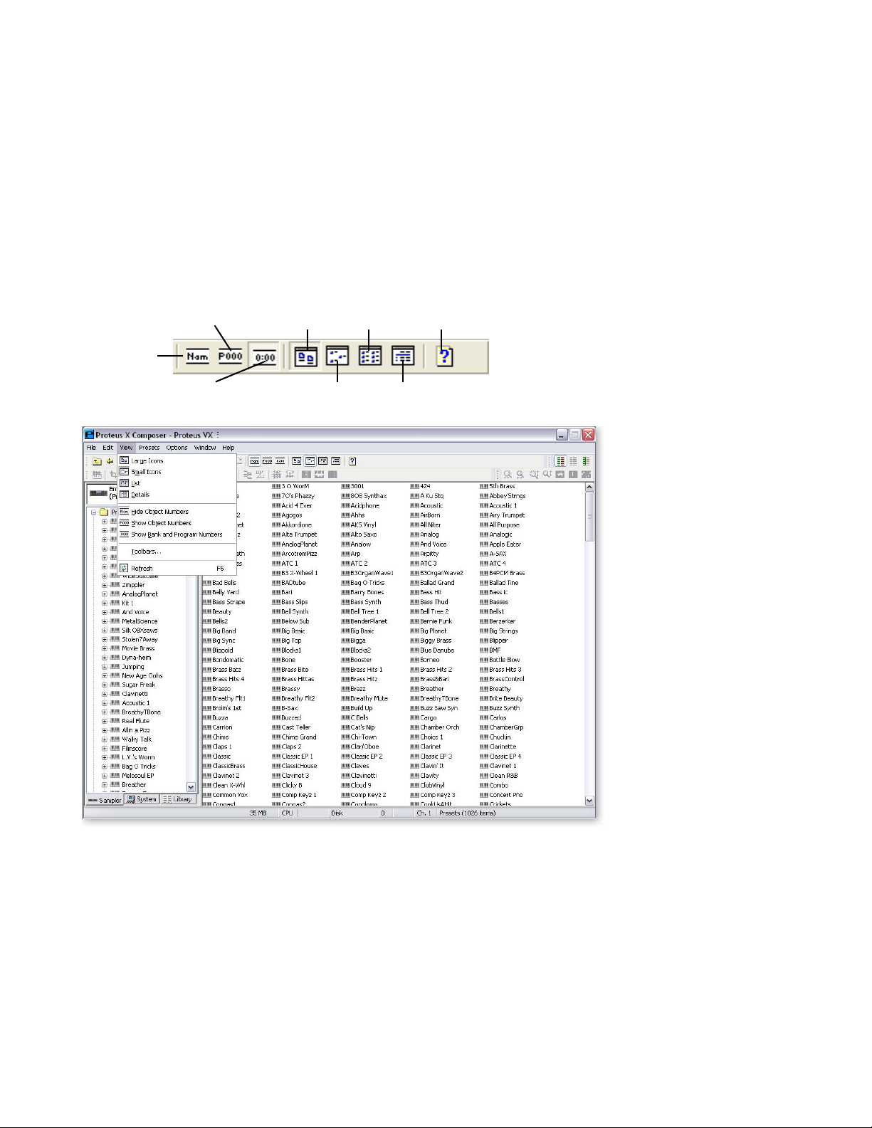
View Menu
The View Menu gives you a grand overview of your presets and multisetups. When the
“Details” view is selected, the ID Number, Bank-Program Number, and Category is
shown for each preset or multisetup. In Details View, lists can be sorted by clicking on
the column header.
The View menu is extremely handy when creating new banks since it allows you to
select multiple presets at a time to delete or to merge into a new bank. (Hint: Drop them
onto the Proteus VX icon.) The View menu also makes it easy to edit the category of
multiple presets.
Show Object
Numbers
Large Icons List
Help
6 - Controls
View Menu
Hide Object
Numbers
Show Bank/Prog No.
Toolbar View
Selection
Small Icons Details
E-MU Systems 99
Page 100

6 - Controls
View Menu
Main Display View
When in the Preset or Multisetup Tree, clicking on the preset folder shows all the
presets in the bank in the large window. The View Menu provides several display
options for presets and multisetups. The view options are listed below:
Large Icons
Small Icons Displays small icons (shown above) useful for large banks
List Displays Presets in a list view format (in numerical order)
Details
Displays large icons useful for smaller banks
Displays the ID Number, Bank-Program Number, and Category.
Clicking on the Category button at the top of each column sorts the
list by that category.
Sort Buttons
Tree View
The Preset or Multisetup Tree items can also be viewed in several ways. The View Menu
provides several display options for the tree. The view options are listed below:
Show/Hide Object Numbers
Show Bank & Program
Numbers
100 Proteus VX Operation Manual
Displays or hides the object number for the
Preset or Multisetup.
Presets can be displayed in the tree with Object
numbers (P003) or with Bank and Program
numbers (002:003).
 Loading...