

Protekdevices DLZ-17A, DLZ-17, DLZ-13CA, DLZ-13C, DLZ-12A Datasheet
...
DLZ-5
8
1
2
3
4
5
6
7
9
10
11
12
13
14
15
16
05008
. . . engineered solutions for the transient environment™
APPLICATIONS
✔ Military & Aerospace Data Line Protection
✔ RS-232 & RS-423
✔ Microprocessor Based Equipment
✔ Multiple Data & Power Bus Line Protection
IEC COMPATIBILITY (EN61000-4)
✔ 61000-4-2 (ESD): Air - 15kV, Contact - 8kV
✔ 61000-4-4 (EFT): 40A - 5/50ns
✔ 61000-4-5 (Surge): 24A, 8/20µs - Level 2 (Line-Gnd) & Level 3 (Line-Line)
FEATURES
✔ MIL-STD-461 Compatible
✔ 1300 Watts Peak Pulse Power per Line (tp=8/20µs)
✔ Unidirectional & Bidirectional Configurations
✔ ESD Protection > 40 kilovolts
✔ Internal Common Ground
✔ Available in Multiple Voltage Types: 5.0V to 30.0V
✔ ✔
✔
PROTECTS UP TO 15 LINES
✔ ✔
thru
DLZ-30CA
STANDARD TVS ARRAYS
16 PIN CERAMIC
MECHANICAL CHARACTERISTICS
✔ Ceramic 16 Pin Hermetically Sealed Package
✔ Weight 3.2 grams (Approximate)
✔ Flammability rating UL 94V-0
✔ Marking: Date Code, Logo, Part Number & Pin One Defined By Flag on Lead
✔ Screened for Military Requirments in Accordance with MIL-PRF-19500
- Standard screening consists of 100% JANTX equivalent level testing per
MIL-PRF-19500
- For ordering these options, use the following suffix:
H1 - 100% JANTX level screening
H2 - 100% JANTX level screening with Group B testing
✔ Screened to DESC Drawing #94029 (Bidirectional) & #94030 (Unidirectional)
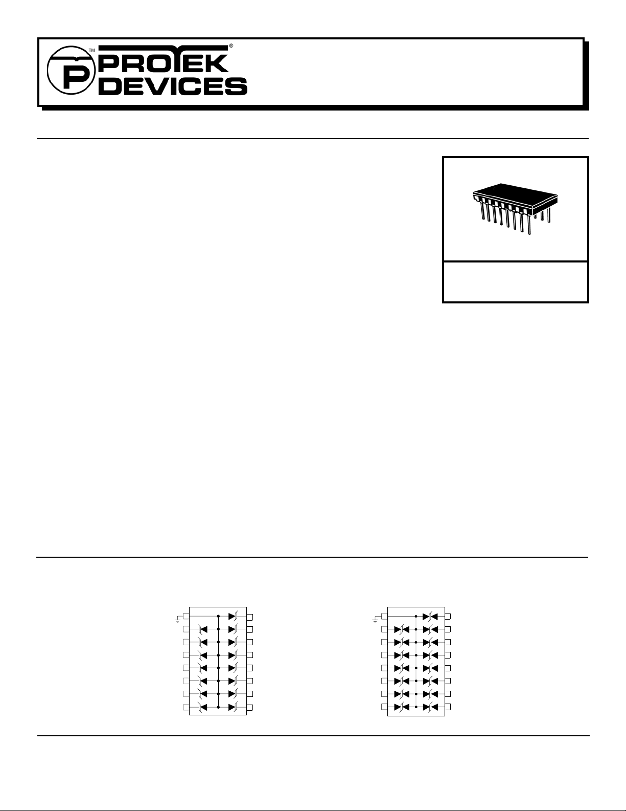
CIRCUIT DIAGRAMS
UNIDIRECTIONAL
1
2
3
4
5
6
7
8
16
15
14
13
12
11
10
9
BIDIRECTIONAL
1
www.protekdevices.com05008.R4 6/02
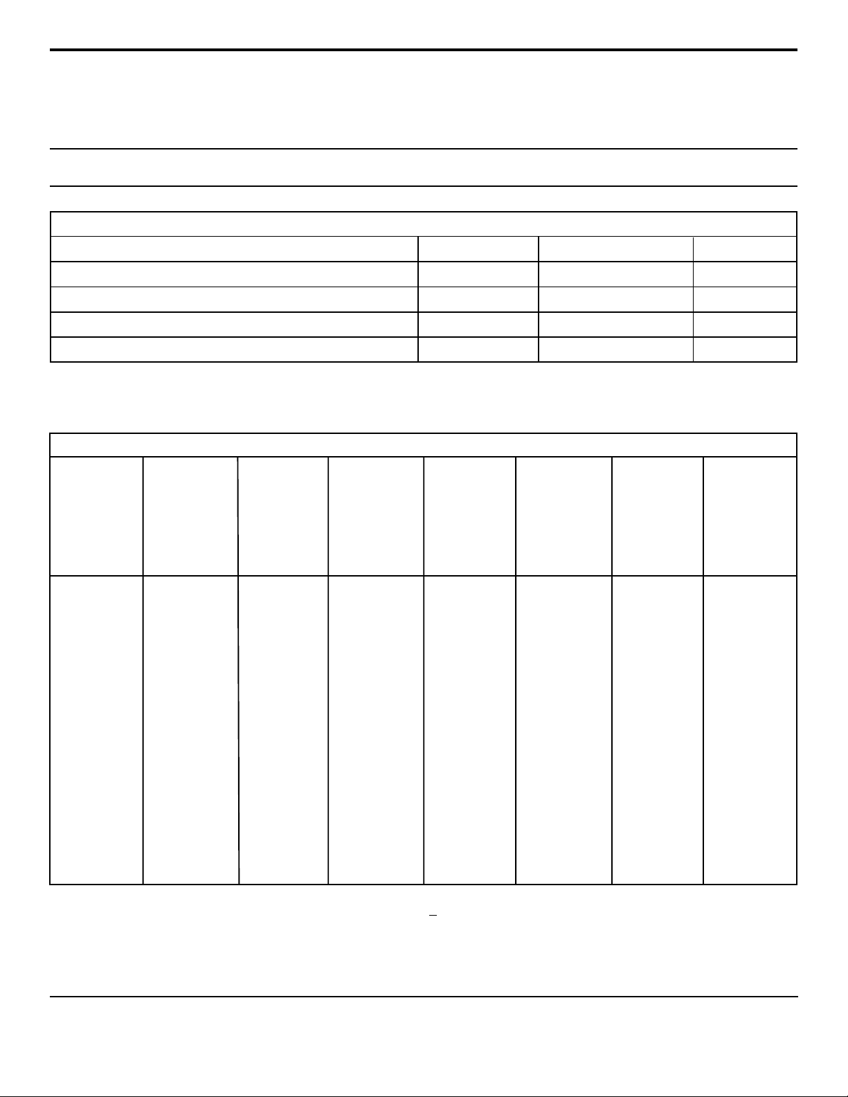
DEVICE CHARACTERISTICS
MAXIMUM RATINGS @ 25°C Unless Otherwise Specified
DLZ-5
thru
DLZ-30CA
PARAMETER
Peak Pulse Power (tp = 8/20µs) - See Figure 1
Operating Temperature
Storage Temperature
Forward Surge Rating (1/20 seconds) - Unidirectional Only Amps10I
SYMBOL VALUE
P
PP
T
J
T
STG
F
1300
-55°C to 150°C
ELECTRICAL CHARACTERISTICS PER LINE @ 25°C Unless Otherwise Specified
PA RT
NUMBER
(Note 1)
DLZ-5
DLZ-5A
DLZ-12
DLZ-12A
DLZ-17
DLZ-17A
DLZ-24
DLZ-24A
DLZ-30
DLZ-30A
RATED
STAND-OFF
VOLTAGE
V
WM
VOLTS
5.0
5.0
12.0
12.0
17.0
17.0
24.0
24.0
30.0
30.0
MINIMUM
BREAKDOWN
VOLTAGE
@ 1mA
V
(BR)
VOLTS
6.0
6.0
13.3
13.3
19.2
19.2
26.7
26.7
33.3
33.3
MAXIMUM
CLAMPING
VOLTAGE
(See Fig. 2)
@ I
= 1 A
P
V
C
VOLTS
10.2
9.5
21.1
19.1
30.4
27.5
42.3
38.3
52.8
47.8
MAXIMUM
CLAMPING
VOLTAGE
(See Fig. 2)
@ 8/20µs
VC @ I
PP
18.1V @ 70A
19.2V @ 66A
28.0V @ 48A
33.0V @ 41A
37.4V @ 35A
40.0V @ 33A
50.5V @ 26A
62.4V @ 21A
62.9V @ 21A
60.0V @ 24A
MAXIMUM
LEAKAGE
CURRENT
@V
WM
I
D
µA
200
200
2
2
2
2
2
2
2
2
MAXIMUM
CAPACITANCE
@ 0V, 1 MHz
C
pF
880
880
440
440
330
330
275
275
220
220
UNITS
Watts
°C-55°C to 150°C
°C
TEMPERATURE
COEFFICIENT
OF V
(BR)
θV
(BR)
mV/°C
5
5
18
18
20
20
31
31
39
39
DLZ-8C
DLZ-13C
DLZ-13CA
DLZ-19C
DLZ-19CA
DLZ-30C
DLZ-30CA
Note 1: Part numbers with a “C” suffix are bidirectional devices, i.e., DLZ-8C.
05008.R4 6/02
8.0
13.0
13.0
19.0
19.0
30.0
30.0
8.5
14.4
14.4
21.6
21.6
33.3
33.3
13.4
22.8
20.6
34.2
31.0
52.8
47.8
2 www.protekdevices.com
29.0V @ 45A
31.0V @ 43A
34.0V @ 39A
40.5V @ 33A
47.6V @ 28A
68.7V @ 19A
62.5V @ 21A
10
440
4
4
4
4
4
4
385
385
275
275
165
165
9
18
18
24
24
39
39
 Loading...