

Page 1
查询P1300EA供应商查询P1300EA供应商
05121
PP0640EA
thru
. . . engineered solutions for the transient environment™
BIDIRECTIONAL THYRISTOR SURGE SUPPRESSOR
APPLICATIONS
✔ T1/E1 Trunk & Line Card
✔ SLIC Line Card
✔ DBX Branch Exchange Switches
✔ FCC Part 68 Customer Premise Equipment
✔ Line Interface Modem
✔ xDSL Architecture Interface
✔ ISDN Architecture Interface
IEC COMPATIBILITY (EN61000-4)
✔ 61000-4-2 (ESD): Air - 15kV, Contact - 8kV
✔ 61000-4-4 (EFT): 40A - 5/50ns
✔ 61000-4-5 (Surge): 24A, 8/20µs - Level 2(Line-Gnd) & Level 3(Line-Line)
FEATURES
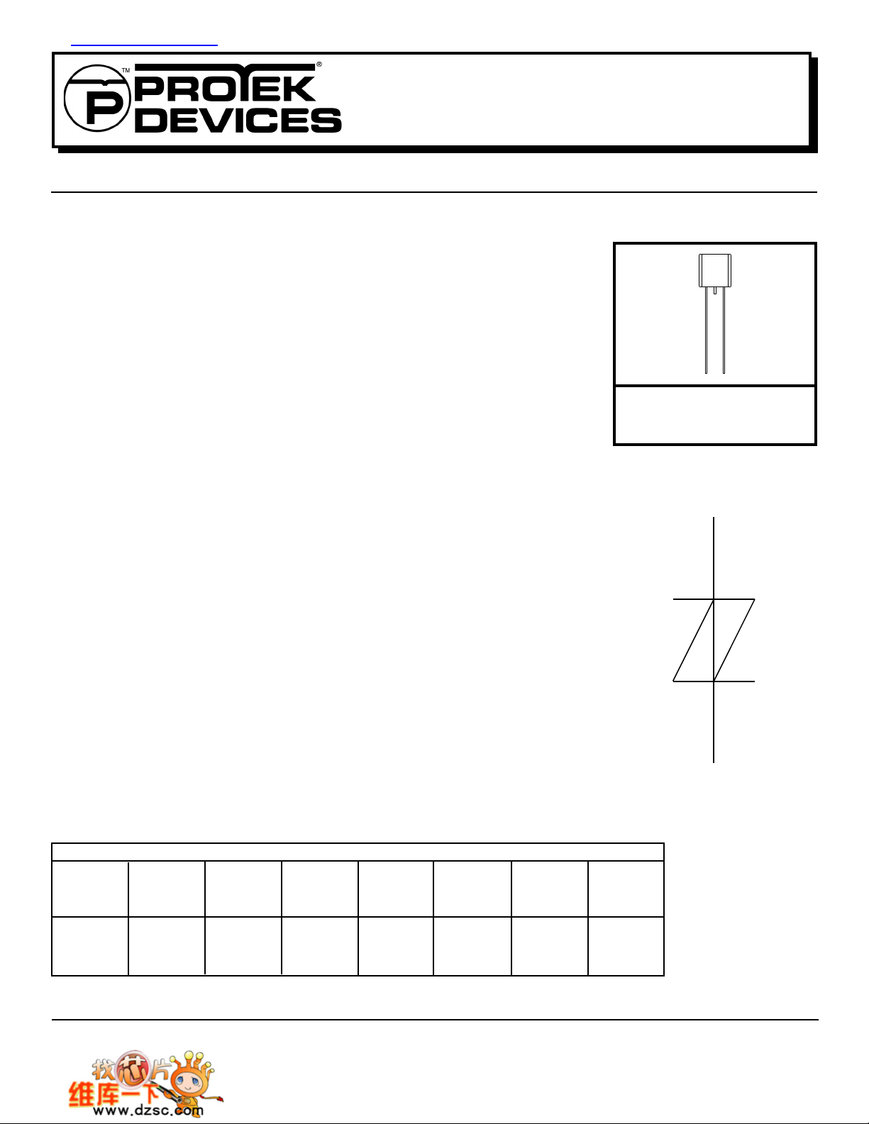
PP3500EC
TO-92
DEVICE SYMBOL
(BIDIRECTIONAL)
✔
Complies with: FCC P art 68, UL 1459, Bellcore 1089, ITU-K.20 & K.21
✔ P eak Off-State V oltage from 58 to 300 Volts
✔ Surge Current Capability(See Tab le 1)
✔ ESD Protection > 40 kilovolts
✔ L ow Capacitance for T1/E1 Trunk & Line Card Applications
MECHANICAL CHARACTERISTICS
✔ Molded T O-92 P ackage
✔ Weight 0.18 grams (Approximate)
✔ Flammability Rating UL 94V-0
✔ Device Marking: Logo & Marking Code
TABLE 1 - SURGE RA TINGS
SERIES I
EA
EB
EC
Note 1: Critital Rate of Rise for On-State Current (di/dt) and Off-State Voltage (dv/dt).
PP
2 X 10µs
AMPS
125
300
500
I
PP
10 X 160µs
AMPS
100
150
200
I
PP
10 X 560µs
AMPS
50
100
200
I
PP
10 X 1000µs
AMPS
50
75
100
I
60 Hz
AMPS
TSM
20
32
60
di/dt
AMPS/µs
(See Note 1)
500
500
500
dv/dt
AMPS/µs
(See Note 1)
2000
2000
2000
1 www.protekdevices.com05121.R1 4/02
Page 2
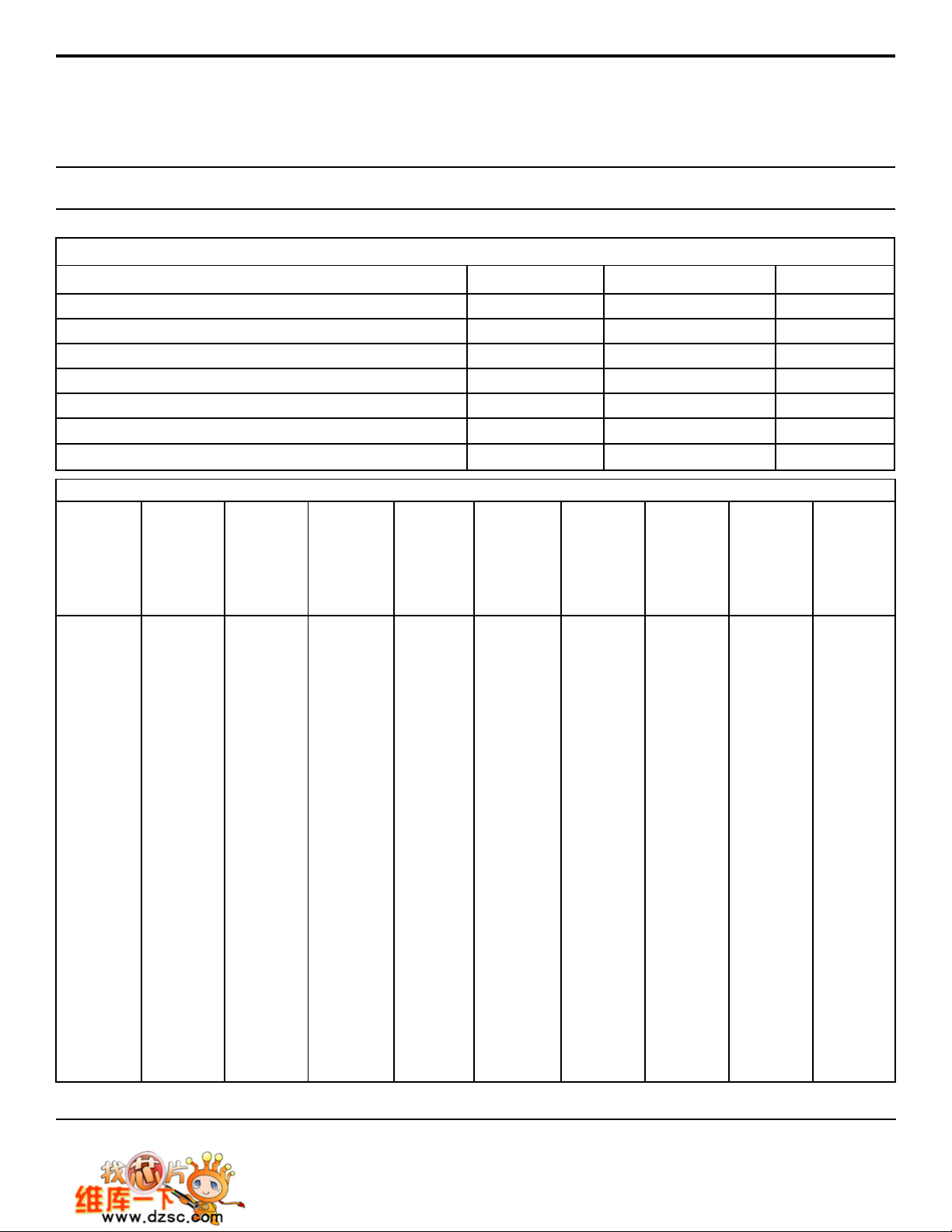
DEVICE CHARACTERISTICS
MAXIMUM RA TINGS @ 25°C Unless Otherwise Specified
PP0640EA
thru
PP3500EC
PARAMETER
Surge Current - 50/60 Hz
Junction Temperature
Storage Temperature
Thermal Resistance(Junction) - EA & EB Series
Thermal Resistance(Junction) - EC Series
Thermal Resistance(Ambient) - EA & EB Series
Thermal Resistance(Ambient) - EC Series
SYMBOL VALUE
I
TSM
T
j
T
STG
R
qjc
R
qjc
R
qjc
R
qjc
ELECTRICAL CHARACTERISTICS PER LINE @ 25°C Unless Otherwise Specified
PART
NUMBER
(See Note 1)
PP0640EA
PP0720EA
PP0800EA
PP1100EA
PP1300EA*
PP1500EA
PP1800EA
PP2300EA*
PP2600EA*
PP3100EA
PP3500EA
PP0640EB*
PP0720EB
PP0800EB
PP1100EB
PP1300EB
PP1500EB*
PP1800EB
PP2300EB
PP2600EB
PP3100EB*
PP3500EB*
PP0640EC*
PP0720EC
PP0800EC
PP1100EC
PP1300EC*
PP1500EC*
PP1800EC
PP2300EC*
PP2600EC
PP3100EC*
PP3500EC*
Note 1: * Indicates preferred a part number.
Note 2: Capacitance imbalance between positive and negative polarities is typically < 15pF .
DEVICE
MARKING
CODE
GC
GD
GE
GF
GG
GH
GI
GJ
GK
GL
GM
GP
GQ
GR
GS
GT
GU
GV
GW
GX
GY
GZ
HC
HD
HE
HF
HG
HH
HI
HJ
HK
HL
HM
REPETITIVE
PEAK
OFF-ST ATE
VOLT AGE
V
DRM
VOLTS
58
65
75
90
120
140
160
190
220
275
300
58
65
75
90
120
140
160
190
220
275
300
58
65
75
90
120
140
160
190
220
275
300
SWITCHING
VOLT AGE
@100V/µs
V
S
VOLTS
77
88
98
130
160
180
220
260
300
350
400
77
88
98
130
160
180
220
260
300
350
400
77
88
98
130
160
180
220
260
300
350
400
MINIMUM
HOLDING
CURRENT
(See Fig. 4)
di/dt = 1A/ms
I
H
mA
150
150
150
150
150
150
150
150
150
150
150
150
150
150
150
150
150
150
150
150
150
150
150
150
150
150
150
150
150
150
150
150
150
SWITCHING
CURRENT
I
S
mA
800
800
800
800
800
800
800
800
800
800
800
800
800
800
800
800
800
800
800
800
800
800
800
800
800
800
800
800
800
800
800
800
800
MAXIMUM
OFF-ST ATE
VOLT AGE
(See Fig. 3)
@V
I
DRM
µA
5
5
5
5
5
5
5
5
5
5
5
5
5
5
5
5
5
5
5
5
5
5
5
5
5
5
5
5
5
5
5
5
5
DRM
60
-40 to 150
-55 to 150
28
26
90
85
MAXIMUM
ON-ST ATE
VOLT AGE
(See Fig. 3)
@I
T
V
T
VOLTS
5
5
5
5
5
5
5
5
5
5
5
5
5
5
5
5
5
5
5
5
5
5
5
5
5
5
5
5
5
5
5
5
5
ON-ST ATE
CURRENT
I
T
AMPS
1.0
1.0
1.0
1.0
1.0
1.0
1.0
1.0
1.0
1.0
1.0
1.0
1.0
1.0
1.0
1.0
1.0
1.0
1.0
1.0
1.0
1.0
1.0
1.0
1.0
1.0
1.0
1.0
1.0
1.0
1.0
1.0
1.0
UNITS
Amps
°C
°C
°C/Watt
°C/Watt
°C/Watt
°C/Watt
TYPICAL
CAP A CITANCE
(See Note 2)
@2V , 1 MHz
C
pF
60
60
60
60
40
40
40
30
30
30
30
60
60
60
60
40
40
40
30
30
30
30
120
120
120
120
80
80
80
60
60
60
60
05121.R1 4/02
2 www.protekdevices.com
Page 3
GRAPHS
PP0640EA
thru
PP3500EC
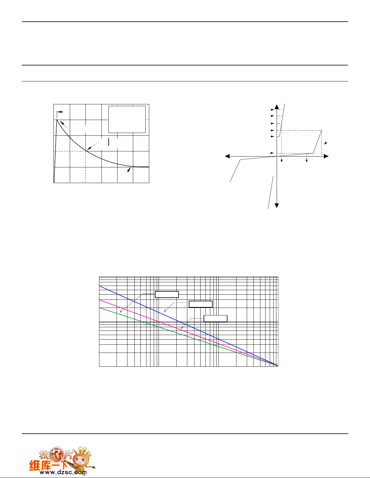
FIGURE 1
100
PP
50
- Peak Pulse Current - % of I
PP
I
0
0 1 2 3
PULSE WAVE FORM
t
f
Peak V alue I
PP
t - Time - µs
100
td = t
TEST
WA VEFORM
P ARAMETERS
t
= 10µs
f
td = 1,000µs
IPP/2
V-I CHARACTERISTIC CURVE
-t
e
FIGURE 3
ON-STATE CURRENT VS SURGE CURRENT DURATION
FIGURE 2
I
PP
I
TSM
I
T
I
S
I
H
I
DRM
V
S
V
T
V
DRM
05121.R1 4/02
) - Amps
TSM
PPxxxxEA
PPxxxxEC
10
Non-Repetitive On-State Current (I
1
1 10 100 1,000
PPxxxxEB
Surge Current Duration - Full Cycles
3 www.protekdevices.com
Page 4
GRAPHS
PP0640EA
thru
PP3500EC
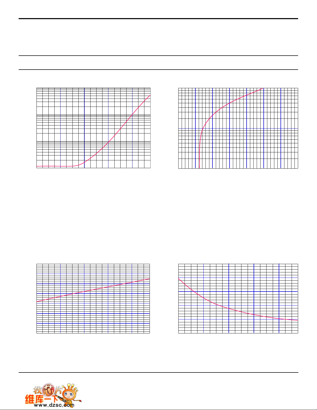
TYPICAL PEAK OFF-STA TE CURRENT VS JUNCTION TEMPERA TURE
10
1
0.1
- Peak Off-State Current - µA
DRM
I
0.01
-40 0 40 80 120
FIGURE 4
- Temperature - °C
t
J
100
10
- On-State Current - A
T
I
1
0 1 2 3 4 5 6 7
TYPICAL ON-STA TE CURRENT VS ON-ST A TE VOL T AGE
FIGURE 5
V
- On-State Voltage - V
T
FIGURE 6
1.15
1.1
1.05
S
0.95
Normalized V
0.9
0.85
0.8
05121.R1 4/02
TYPICAL NORMALIZED V
1
-40 0 40 80 120
VS JUNCTION TEMPERATURE
S
t
- Temperature - °C
J
2.5
1.5
25°C)
J
(t
H
/I
H
I
0.5
4 www.protekdevices.com
TYPICAL HOLDING CURRENT VS JUNCTION TEMPERA TURE
2
1
0
-40 0 40 80 120
FIGURE 7
- Temperature - °C
t
J
Page 5
APPLICATION NOTES
Tip
R
To
Protected
Equipment
Ring
R
TIP
RING
PP0640EA
thru
PP3500EC
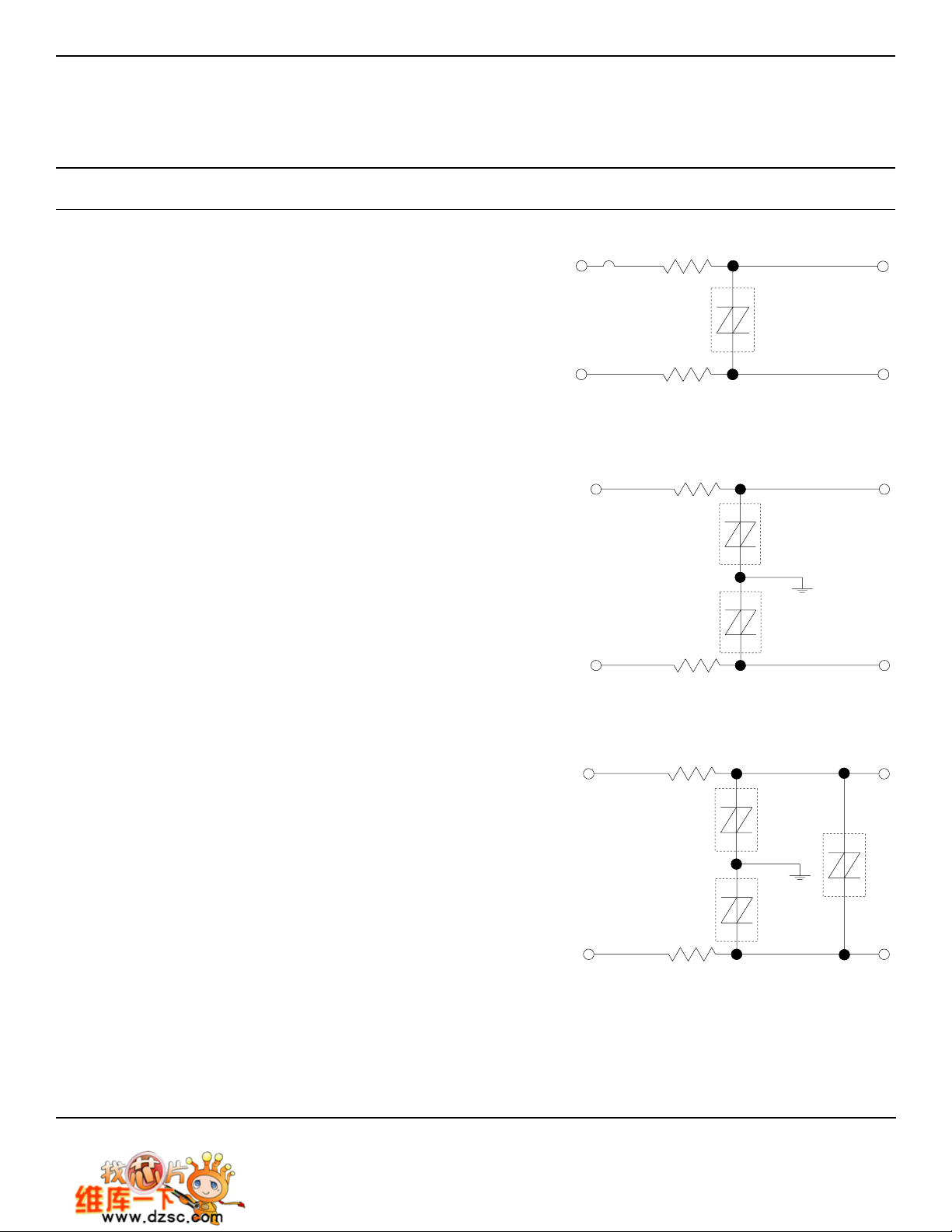
FIGURE 1: UL 1459 & FCC Part 68 - Metallic Protection
The TSS (Thyristor Surge Suppressor) device is located across the
tip-to-ring after a limiting resistor and fuse combination. R
resistors are optional depending upon the TSS device
R
RING
selection. Without the resistors, the PP3100EB/EC is recommended.
TIP
and
However, with a resistance value of 7.5 Ohms for tip and ring, the
PP3100EA is recommended. Digital signals may use a lower TSS
device depending upon the total tip to ring voltage range. Selection
of the TSS device, either PPxxxxEA or EB/EC is based upon the
value of the tip and ring resistors. For the National Electric Code
(NEC) article 800, it is recommended that at least one fuse be used
in the tip or ring line for metallic surges. Fuses may be replaced with
a suitable Positive Temperature Coefficient (PTC) automatic
resettable current limiting device.
FIGURE 2 - UL 1459 & FCC Part 68 - Longitudinal Protection
There are two TSS devices, one located from tip-to-ground and one
ring-to-ground. For standard analog signals, the PP3100EA is
recommended with a typical resistor value for tip and ring of 15
Ohms. The PP3100EB/EC is recommended for resistor values of
7.5 Ohms each. The National Electric Code (NEC) article 800
requires two fuse elements when connecting to ground. Fuses or a
suitable Positive Temperature Coefficient (PTC) automatic resettable
current limiting device may be used. The purpose of this circuit is to
limit AC power current from getting on the ground line causing any
safety hazard.
FIGURE 3 - UL 1459 & FCC Part 68 - Metallic & Longitudinal
Protection
TIP
RING
R
Fuse
Tip
R
Ring
FIGURE 1 - Metallic Protection
FIGURE 2 - Longitudinal Protection
To
Protected
Equipment
Three equal TSS devices are used in this application for metallic (tipto-ring) and longitudinal (tip-to-ground and ring-to-ground) protection.
For analog signals, the PP3100EB/EC is recommended. With a
resistance value of 15 Ohms for the tip and ring resistors, the
PP3100EA may be used. The National Electric Code (NEC) article
800 requires two fuse elements when connecting to ground. Fuses
or a suitable Positive Temperature Coefficient (PTC) automatic
resettable current limiting device may be used. This circuit is
recommended for protection against the Bellcore requirement: First
Level Lightning Surge Tests (Telecommunications Port), document #
GR-1089-CORE.
05121.R1 4/02
R
TIP
RING
Tip
To
Protected
Equipment
R
Ring
FIGURE 3 - Metallic & Longitudinal Protection
5 www.protekdevices.com
Page 6
PACKAGE OUTLINE & DIMENSIONS
PP0640EA
thru
PP3500EC
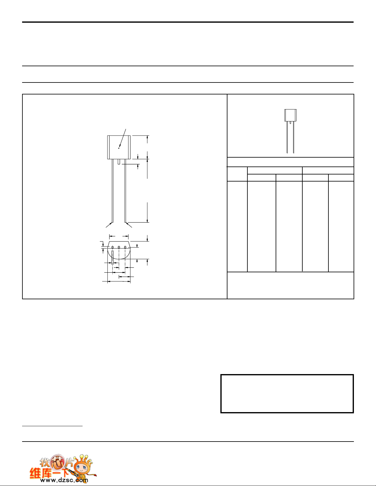
PACKAGE OUTLINE
TC MEASURING POINT
A
N
B
PIN 3PIN 1
M
E
G
H
L
D
J
F
K
TO-92
DIMENSIONS
0.176
0.500
0.095
0.150
0.046
0.135
0.088
0.176
0.088
0.015
0.013
-
INCHES
0.196
0.105
0.054
0.145
0.096
0.186
0.096
0.020
0.017
0.060
MILLIMETERS
DIM MIN MAX MIN MAX
A
B
D
E
F
G
H
J
K
L
M
N
NOTES:
1. All leads insulate from case. Case is electrically
nonconductive.
4.47
12.70
2.41
3.81
1.16
3.43
2.23
4.47
2.23
0.38
0.33
-
4.98
-
2.67
-
1.37
3.68
2.44
4.73
2.44
0.51
0.43
1.52
06031 Rev 0 - 4/02
-
-
ProT ek De vices
2929 South Fair Lane, Tempe, AZ 85282
T el: 602-431-8101 Fax: 602-431-2288
E-Mail: [email protected]
Web Site: www.protekdevices.com
COPYRIGHT © ProTek Devices 2001
SPECIFICATIONS: ProTek reserves the right to change the electrical and or mechanical characteristics described herein without notice (except JEDEC).
DESIGN CHANGES: ProTek reserves the right to discontinue product lines without notice, and that the final judgement concerning selection and specifications is the buyer’s and that in furnishing
engineering and technical assistance, ProTek assumes no responsibility with respect to the selection or specifications of such products.
05121.R1 4/02
6 www.protekdevices.com
 Loading...