

Page 1
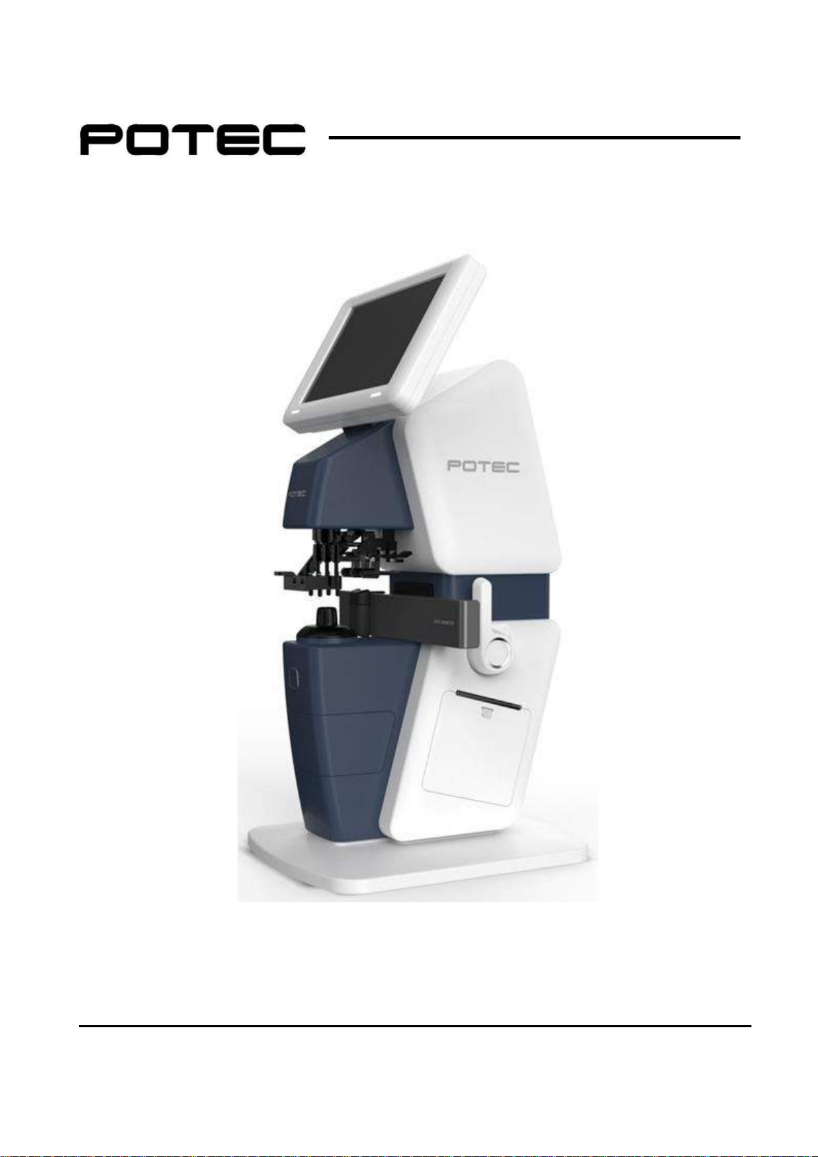
OPERATION MANUAL
AUTO LENSMETER PLM-8000
Revision 1.0 (2017.11) www.potec.biz
Before use, read this manual carefully.
Page 2

PLM-8000 Operation Manual
IMPORTANT NOTICE
This product may malfunction due to electromagnetic waves caused by portable personal
telephones, transceivers, radio-controlled toys, etc. Be sure to avoid having objects such as,
which affect this product, brought near the product.
The information in this publication has been carefully checked and is believed to be entirely
accurate at the time of publication. POTEC assumes no responsibility, however, for possible
errors or omissions, or for any consequences resulting from the use of the information
contained herein.
Upon request, circuit diagrams, component part lists, descriptions, calibration instructions, or
other information will be provided to assist service personnel to repair parts of the equipment
that are designated by POTEC as repairable by service personnel.
POTEC reserves the right to make changes in its products or product specifications at any
time and without prior notice, and is not required to update this documentation to reflect such
changes
© 2017 POTEC Co., Ltd.
40-4, Techno 2-ro, Yuseong-gu, Daejeon, 34015, Korea
All rights reserved.
Under copyright laws, this manual may not be copied, in whole or in part, without the
prior written consent of POTEC.
I
Page 3
PLM-8000 Operation Manual
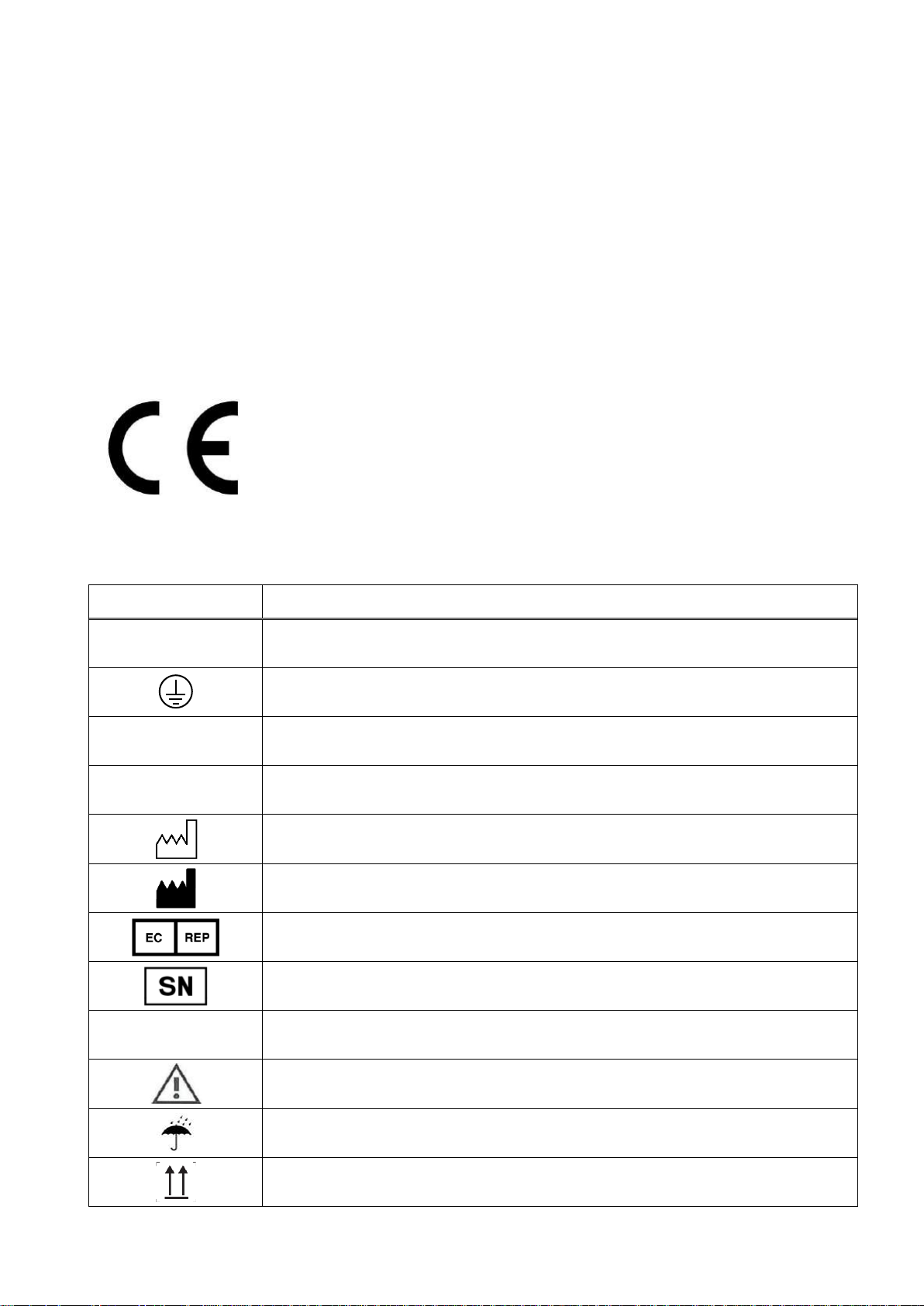
Symbol
Description
~
Alternating current
Protective earth (ground)
I
On (power: connection to the mains)
O
Off (power: disconnect to the mains)
Year of manufacture
Manufacturer
Authorized Representative in the European Community
Serial no.
Follow operating instructions
the instructions for use in the operation manual
Keep dry
This way up
SAFETY INFORMATION
If you see any warnings or cautions printed on the warning labels, follow the safety
instructions in this manual. Ignoring such cautions or warnings while handling the product
may result in injury or accident. Be sure to read and fully understand the manual before using
this product.
Keep this manual in easy-to-access place.
For EU Countries
The following mark, the name & address of the EU Representative shows compliance of the
instrument with Directive 93/42/EEC.
EU Representative:
Medical Device Safety Service GmbH
Schiffgraben 41, D-30175
Hannover, Germany
Symbols marked on the Instrument
II
Page 4
PLM-8000 Operation Manual
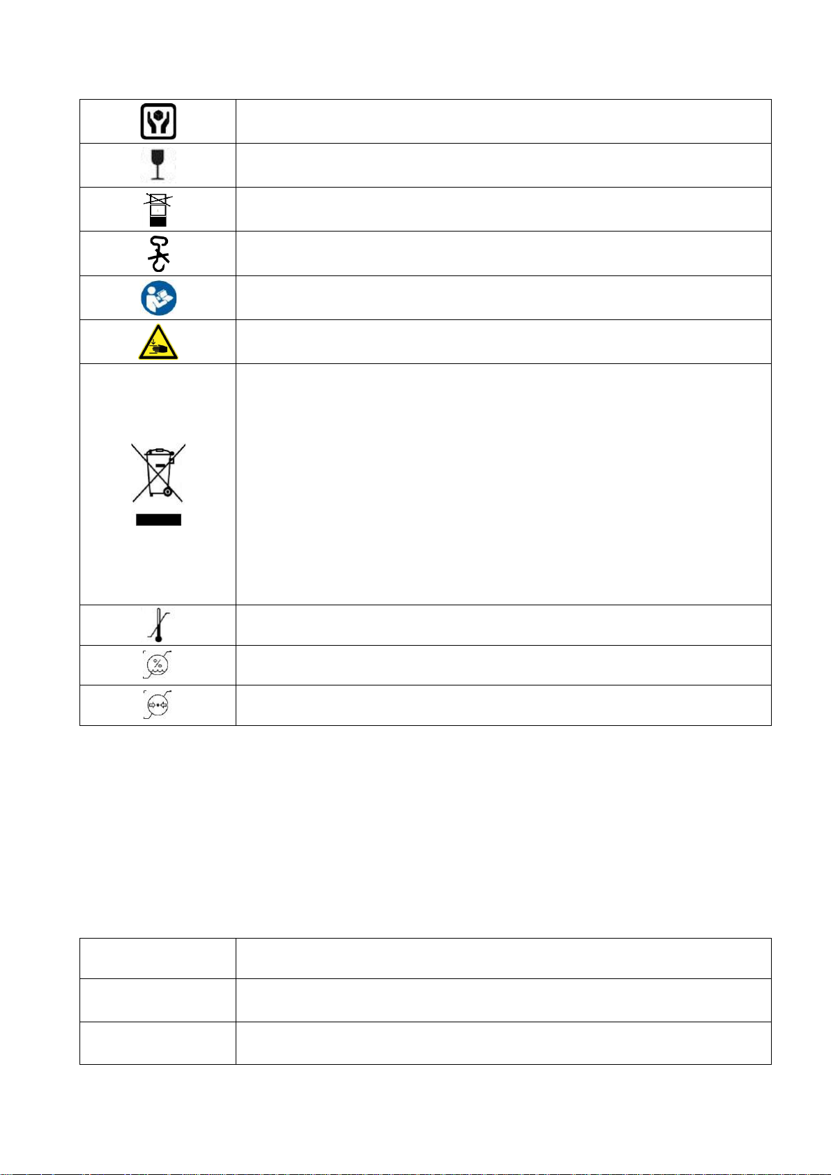
Handle with care
Fragile
Do not build up more than 4 boxes
Do not use hand-hooks
Refer to instruction manual
This indicates hazardous situations which may result in crush your
hand
Disposal of your old appliance
When this crossed-out wheeled bin symbol is attached to a
product it means the product is covered by the European Directive
2012/19/EU (effective since 14.02.2014).
All electrical and electronic products should be disposed of
separately from the municipal waste stream via designated
collection facilities appointed by the government or the local
authorities.
The correct disposal of your old appliance will help prevent
potential negative consequences for the environment and human
health.
For more detailed information about disposal of your old
appliance, please contact your city office, waste disposal service
or the shop where you purchased the product
-40℃
70℃
Temperature between - 40℃~ 70℃
10%
95%
Humidity between 10%RH ~ 95%RH
50kPa
106kPa
Air pressure between 50kPa ~ 106kPa
Caution Sign
Description
WARNING
This indicates a potentially hazardous situation which could results in
death or serious injury to you or others.
CAUTION
This indicates hazardous situations which may result in minor injury to
you or others, or may result in machine damage.
General Safety Information
If you see any warnings or cautions printed on the warning labels, follow the safety
instructions in this manual. Ignoring such cautions or warnings while handling the product
may result in injury or accident. Be sure to read and fully understand the manual before using
this product.
Keep this manual in easy-to-access place.
III
Page 5
PLM-8000 Operation Manual
This is used to emphasize essential information. Be sure to read this
information to avoid incorrect operation.
WARNING
Only operate the instrument with the power supply indicated on the
rating plate. Otherwise, it may result in fire or electric shock.
WARNING
Be sure to turn OFF the power switch before connecting or
disconnecting the cables. Also, do not handle them with wet hands.
Otherwise, you may get an electric shock that may result in death or
serious injury.
WARNING
Never disassemble or modify this instrument because it may result in
fire or electric shock. Also, since this instrument incorporates highvoltage parts and other hazardous parts, touching them may cause
death or serious injury.
WARNING
Should any of the following occur, immediately turn OFF the power
switch, unplug the power cable from the AC outlet, and contact the
dealer or the agent who/where you purchase this instrument.
When there is smoke, strange odor or abnormal sound.
When liquid has been spilled into the instrument or a metal object
has entered through an opening.
When the product has been dropped or its housing damaged.
CAUTION
This instrument is shipped with a grounding type power cable. To
reduce the risk of electric shock, always plug the cable into a
grounded power outlet.
CAUTION
Do not use the device simultaneously with other electronic equipment
to avoid electromagnetic interference with the operation of the device.
CAUTION
Do not use the device near, on, or under other electronic equipment to
avoid electromagnetic interference with the operation of the device.
CAUTION
Do not use the device simultaneously with portable and mobile radio
frequency communication systems because it may have an adverse
effect on operation of the device.
CAUTION
Do not use cables and accessories that are not specified for the
device because that may increase the emission of electromagnetic
waves from the device or the system and decrease the immunity of
the device to electromagnetic disturbance.
CAUTION
Do not to position ME equipment to make it difficult to operate the
disconnection device when an appliance coupler or separable plug is
used as isolation places.
CAUTION
Do not place your fingers between the body and LCD. Otherwise,
hand or fingers may be hurt.
CAUTION
During UV transmittance measurement, ultraviolet rays are emitted
from the LED source.
CAUTION
During Blue transmittance measurement, blue rays are emitted from
the LED source.
CAUTION
Do not place the multiple socket-outlet for PLM-8000 system on the
floor in order to prevent liquid penetration and damage to the product.
CAUTION
PLM-8000 system shall not be connected with additional multiple
socket-outlets or extension cords in addition to a designated single
multiple socket-outlet.
NOTE
IV
Page 6
PLM-8000 Operation Manual
CAUTION
Maximum permissible load of each socket-outlet used for the PLM8000 system, shall not be less than 100VA.
CAUTION
If non-medical electrical equipment (e.g. Video monitor, IT equipment,
etc.) that may be connected with PLM-8000 are, directly connected to
the wall socket-outlets, high touch current may flow since the earth
continuity is not ensured.
CAUTION
Multiple socket-outlet should be a grounding-type and complied with
IEC 60884-1.
CAUTION
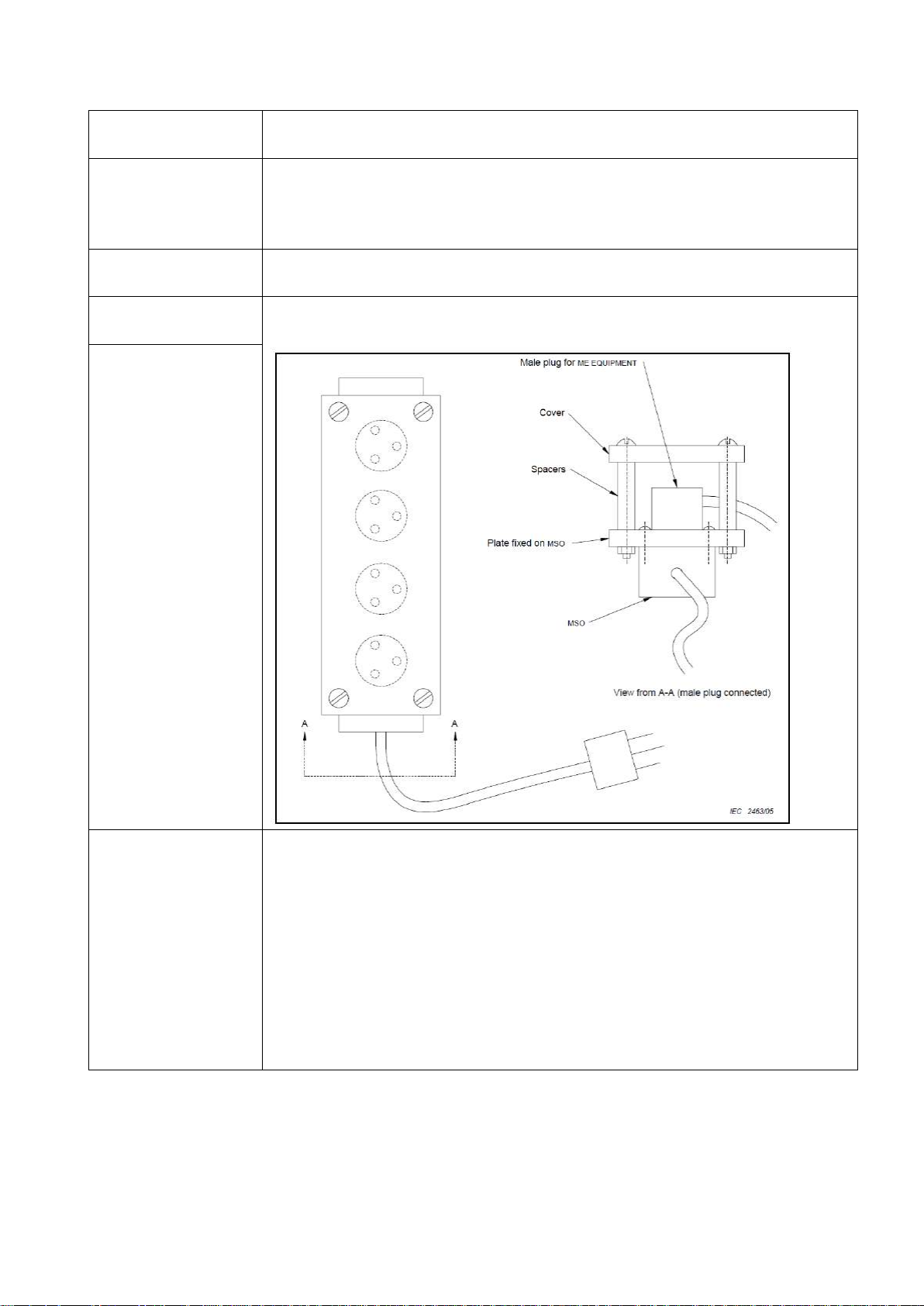
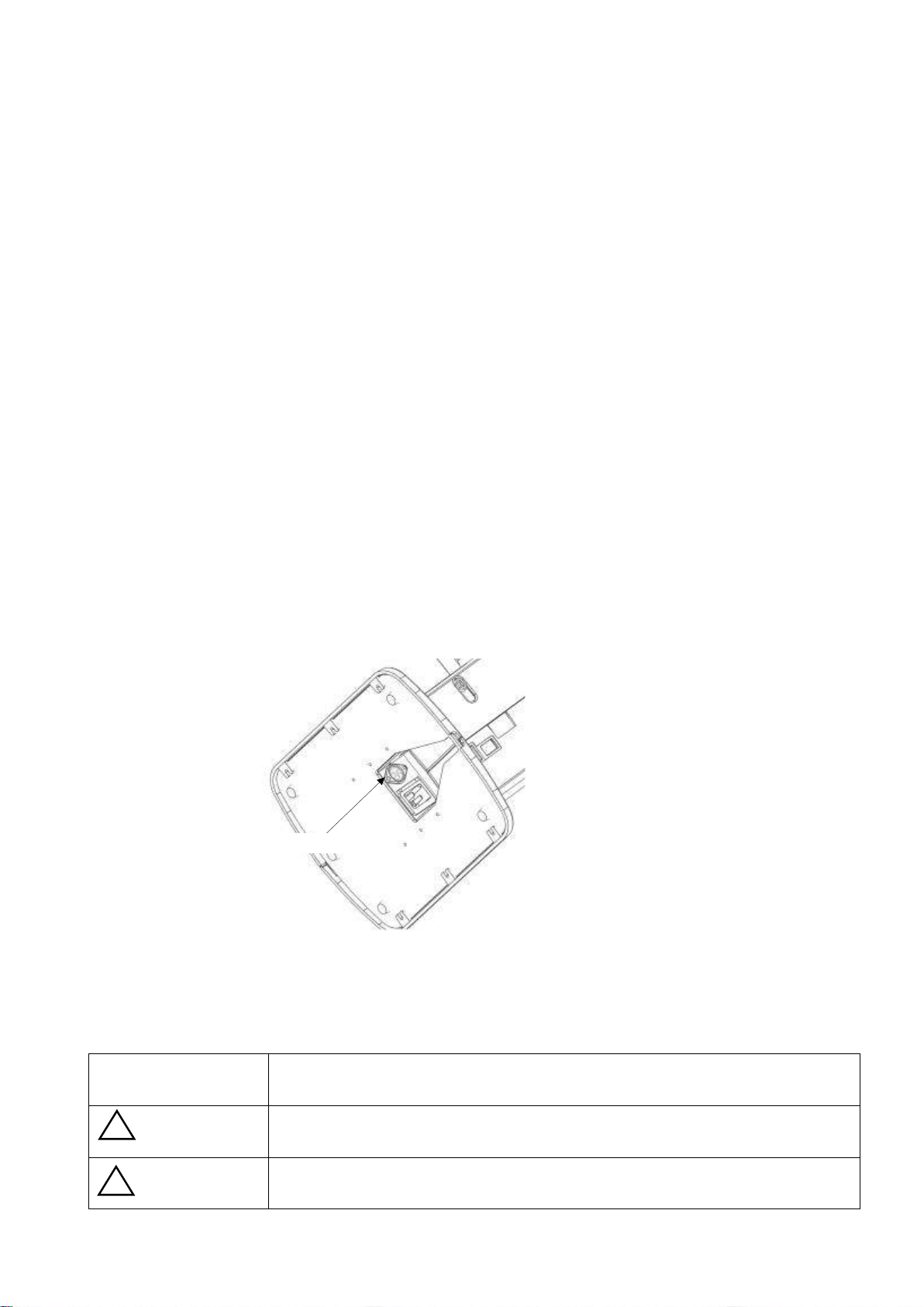
Connection of the plug shall be possible only by using the tool.
(Refer to the figure below.)
NOTE
SAFETY INFORMATION - Accessory equipment connected to the
analog and digital interfaces must be certificated according to the
respective IEC standards (e.g. IEC 60950-1 for data processing
equipment and IEC 60601-1 for medical equipment). Furthermore all
configurations shall comply with the system standard EN 606011:2006, Clause 16. Everybody who connects additional equipment to
the signal input part or signal output part configures a medical system,
and is therefore responsible that the system complies with the
requirements of the system standard (IEC 60601-1:2005, Clause 16).
If in doubt, consult the technical service department or your local
representative.
V
Page 7
PLM-8000 Operation Manual
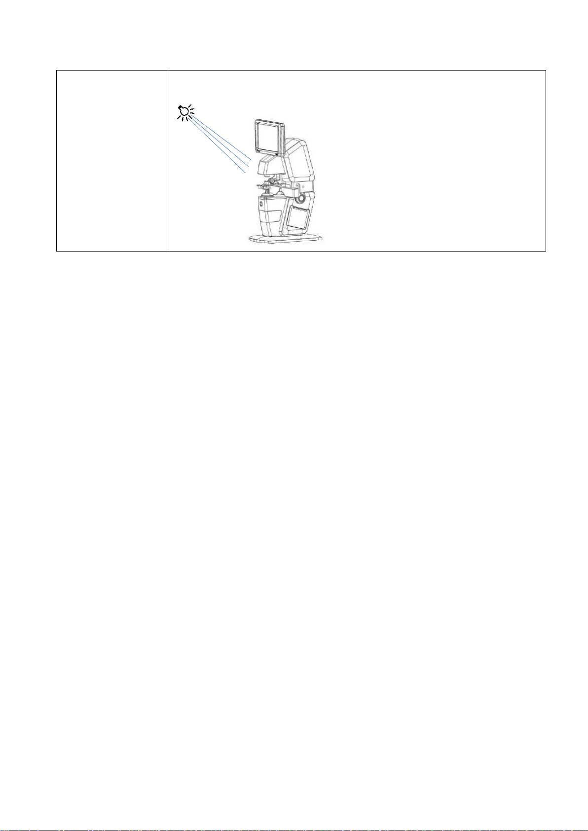
NOTE
Do not expose the device to sunlight or bright light from lighting
equipments.
VI
Page 8
PLM-8000 Operation Manual
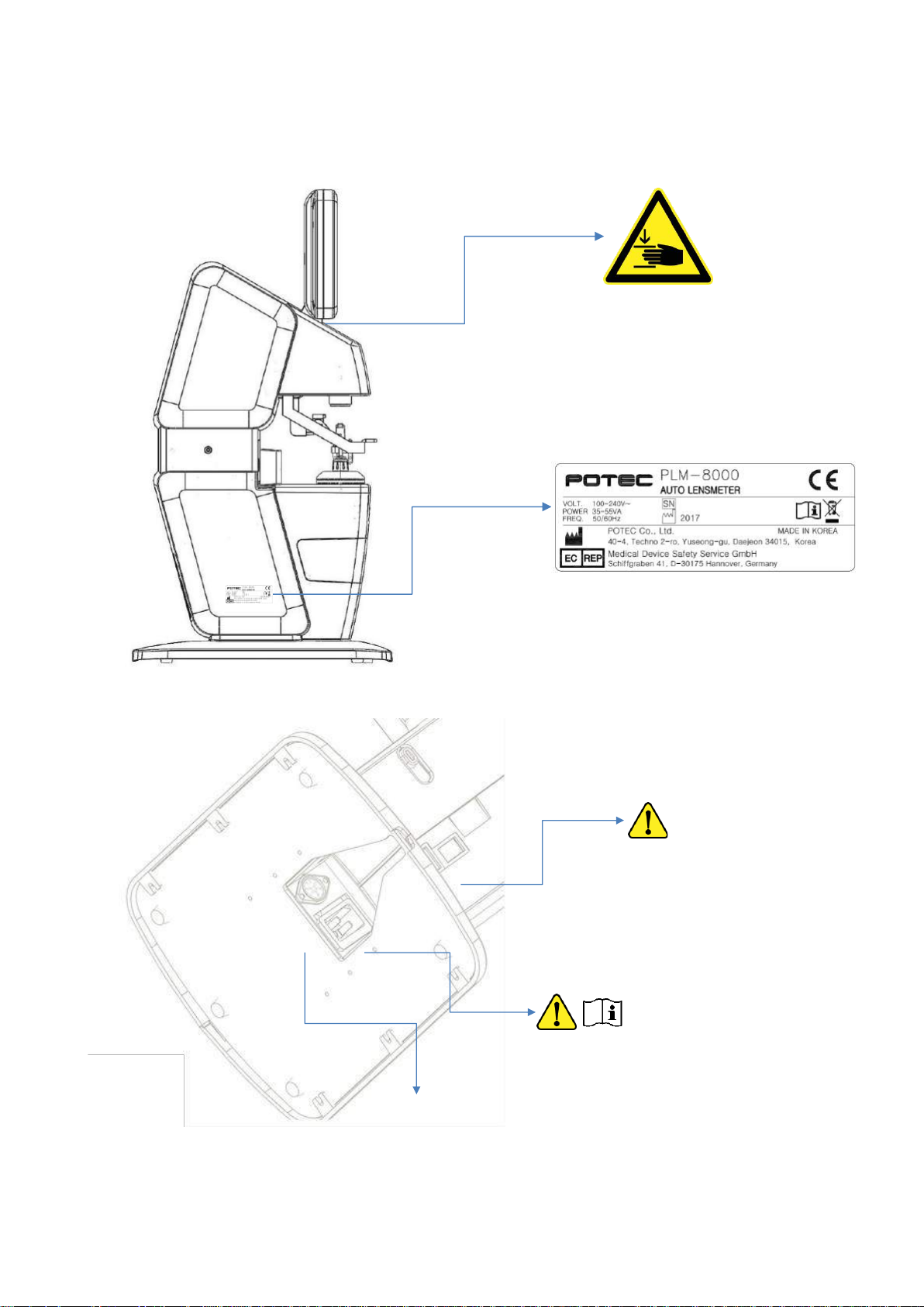
T3.15AH 250V RS232C
Label
VII
Page 9

PLM-8000 Operation Manual
CONTENTS
IMPORTANT NOTICE ................................................................................................................................................... I
SAFETY INFORMATION ............................................................................................................................................ II
For EU Countries .......................................................................................................................................................... II
Symbols marked on the Instrument............................................................................................................................ II
General Safety Information ......................................................................................................................................... III
Label ............................................................................................................................................................................ VII
1. Introduction ............................................................................................................................................................... 3
1.1 General description .................................................................................................................................. 3
1.2 Classifications ............................................................................................................................................. 3
2. Features ...................................................................................................................................................................... 4
3. Notes for Using the Instrument ..................................................................................................................... 5
4. Description ................................................................................................................................................................ 6
4.1 Configuration ................................................................................................................................................ 6
4.2 Accessories ................................................................................................................................................... 7
4.3 Installation and Preparation ................................................................................................................ 8
4.3.1 Preparation before use .......................................................................................................................... 8
4.3.2 Instruction and operation sequence .................................................................................................... 8
4.3.3 Storage after use .................................................................................................................................... 9
4.4 Operating panel ......................................................................................................................................... 10
4.4.1 Basic operation ..................................................................................................................................... 10
4.4.2 Measurement display ........................................................................................................................... 10
4.4.3 UV/BLUE Display ................................................................................................................................. 12
4.4.4 PD Display ............................................................................................................................................. 13
4.4.5 User Setup display ............................................................................................................................... 14
5. Measurement ................................................................................................ ................................ .......................... 19
5.1 Preparation .................................................................................................................................................. 19
5.2 Measuring general lenses ................................................................................................................... 19
5.3 Measuring multi-focal lenses ................................................................................................ ............ 20
5.3.1 Structure of the progressive power lens ........................................................................................... 20
5.3.2 Measuring progressive power lenses ................................................................................................ 20
5.3.3 Measuring Bifocal / Trifocal Lenses ................................................................................................... 21
5.4 Measuring contact lenses ................................................................................................................... 22
5.5 Measuring UV / BLUE ............................................................................................................................ 23
5.6 Measuring prismatic lenses ............................................................................................................... 23
5.7 Measuring PD / OH ................................................................................................................................. 23
5.8 Power-saving mode ................................................................................................................................. 24
1
Page 10

PLM-8000 Operation Manual
5.9 Connection with external optometry equipment..................................................................... 24
6. Self-diagnosis and Maintenance ................................................................................................................ 25
6.1 Before contacting the service personnel ................................................................................... 25
6.2 Replacing Print paper ............................................................................................................................ 26
6.3 Replacing Ink cartridge ........................................................................................................................ 27
6.4 Cleaning the device ................................................................................................................................ 27
6.5 Cleaning the cover glass ..................................................................................................................... 28
6.6 Fuse Replacement ................................................................................................................................... 28
6.7 Service Information ................................................................................................................................. 29
7. Specification ........................................................................................................................................................... 30
7.1 Specifications ............................................................................................................................................. 30
7.2 Components ................................................................................................................................................. 31
2
Page 11

PLM-8000 Operation Manual
1. Introduction
1.1 General description
This device aims to take the measurements of vertex powers, cylinder axis, prismatic power
and prism base setting within a restricted area of unprocessed lens, processed framed lens
and contact lens, Auto Lensmeter PLM-8000 also has functions to measure UV/BLUE
transmission.
As an external feature, the angle of the LCD can be changed. User is able to measure the
PD and OH value with the horizontal and vertical ruler GUI after adjusting the extended LCD
at the lowest angle.
1.2 Classifications
Classification of equipment: Class I / Rule 12 (MDD, Annex IX)
Protection against electric shock: Class I;
Applied part of equipment: No applied part (ok);
Protection against harmful ingress of water: Ordinary (IPX0) (ok);
Method of sterilization: Not applicable (ok);
Stability of use in an Oxygen Rich Environment: Not suitable (ok);
Mode of operation: Continuous operation (ok)
3
Page 12

PLM-8000 Operation Manual
2. Features
(1) Measuring various lenses
This auto lensmeter can measure single vision lenses, bifocals (trifocals) lenses,
progressive power lenses, and contact lenses.
(2) Wide measurement range of refractive powers
The PLM-8000 has a wide measurement range of refractive powers from -25D to
+25D, which even enables the measurement of lens for the severely nearsighted.
(3) Measurement of UV and Blue transmission of a lens.
(4) Easily connectable to other devices
This lensmeter is designed in such a way that the lensmeter can be easily connected
to other devices(PC, PRK-Series, PDR-8000).
(5) Built-in the printer
The PLM-8000 has built-in printer so it is possible to print the measurement data
easily.
(6) User is able to measure the height of the optical center with glasses PD and frame
information.
4
Page 13

PLM-8000 Operation Manual
In use
Temperature : +10℃ ~ +40℃
Humidity : 30% ~ 90% RH
Pressure : 80 ~ 106 kPa
In storage
(non packaging)
Temperature : -10℃ ~ +55℃
Humidity : 10% ~ 95% RH
Pressure : 70 ~ 106 kPa
In transport & storage
(packing)
Temperature : -40℃ ~ +70℃
Humidity : 10% ~ 95% RH
Pressure : 50 ~ 106 kPa
NOTE
“In storage(non packaging)” state is as follows;
Specimen unprotected, ready for operation, power supply not
connected
3. Notes for Using the Instrument
(1) Do not strike or drop the instrument. Strong impact causes the instrument to be
damaged and malfunction. Handle the instrument carefully.
(2) Do not expose the instrument directly to sunlight or bright indoor lighting, as this may
affect the precise measurement of the instrument.
(3) When other devices are to be connected to the instrument, follow the guidance of the
suppliers of the devices.
(4) Be sure to keep the cover glass clean. If the cover glass is contaminated with dust or
foreign matter, the instrument may malfunction or perform inaccurate measurement.
(5) If you encounter any abnormal condition, such as smoke, smell, or noise, when in use,
pull out the power cord immediately, and then follow the guidance of the supplier.
(6) Never use an organic solvent, such as alcohol, thinner, benzene, etc., to wipe the
exterior. It may ruin the surface of the instrument.
(7) When the PLM-8000 is to be moved, be sure to confirm that the power switch is
turned OFF. Then, move the instrument while holding the lower part of the main body
with both hands.
(8) When the PLM-8000 is not used at the long time, please turn off the power and put
the dust cover.
(9) Environment conditions.
5
Page 14
PLM-8000 Operation Manual
Name
Function
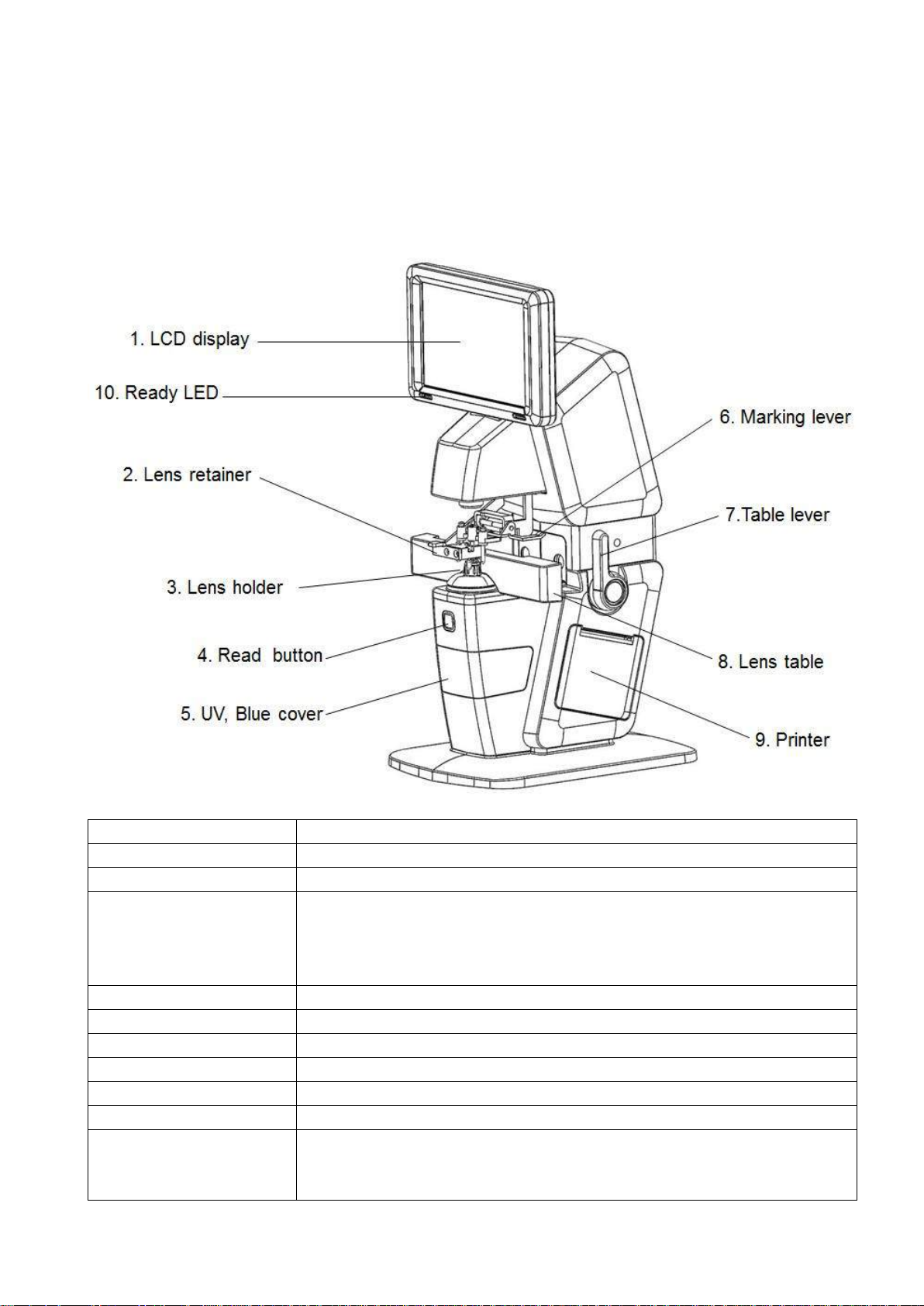
1. LCD Display
7.0 inch TFT Color LCD Monitor, Touch
2. Lens retainer
To fix the lens
3. Lens holder
Measure the lens when the lens is fixed on the lens holder. This
is the basis for measurements
When measuring contact lenses, replace them with the supplied
contact lens holder
4. Read button
To read measured data
5. UV, Blue cover
For UV / Blue transmittance measurements
6. Marking lever
Mark a lens by pushing the lever down
7. Table lever
Move the lens table forward and backward
8. Lens table
Touched the eye glasses frame
9. Printer
Printing the measurement data
10. Ready LED
The LED is illuminated in the direction of the lens being measured
When measuring a single lens, all LEDs are off.
When in the power save mode, it blinks every 5 seconds.
4. Description
4.1 Configuration
6
Page 15
PLM-8000 Operation Manual
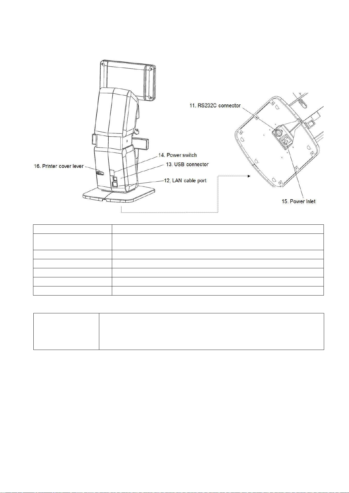
Name
Function
11. RS232C connector
To connect communication with other equipment(PC, PRK-Series,
PDR-7000)
12. LAN cable port
-
13. USB connector
To upgrade S/W, Not for everyday use
14. Power switch
Turn on or off power the device
15. Power Inlet
Connect a power cord
16. Printer cover lever
To open the printer cover at the time of replacing the printer paper
CAUTION
If you want to connect the input / output signal ports and other devices
that must meet IEC standards (IEC60950 IT equipment, IEC60601
medical equipment)
If in doubt should contact POTEC or your authorized distributor.
4.2 Accessories
(1) Operation manual
(2) Contact lens support
(3) Dust cover
(4) Power cable
7
Page 16
PLM-8000 Operation Manual
(1) Open the box.
(2) Make sure all articles are there (printing paper, dust cover, Operator’s Manual
etc.).
(3) Set the device on the table.
NOTE
Don’t install the machine under bright light or avoid surrounding bright
light and direct sun light for better result.
NOTE
Move the device with both hands at the lower part of the main body
(4) Remove protection tapes on lens holder, marking lever, table lever and UV,Blue
cover.
(5) Remove dusts, especially on the cover glass.
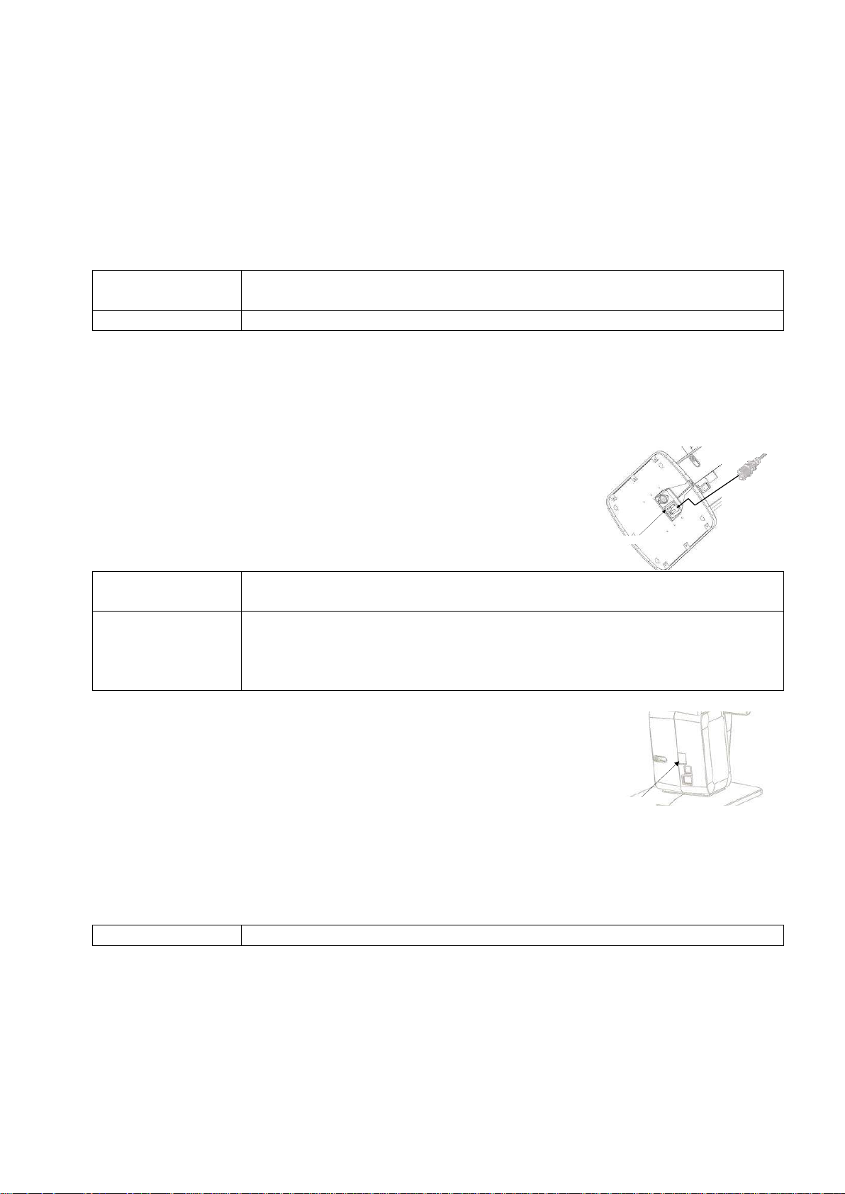
(1) Connect the power cord on the bottom parts of device
to provide power.
Power Inlet
WARNING
Only operate the instrument with the power supply indicated on the
rating plate. Otherwise, it may result in fire or electric shock.
WARNING
Be sure to turn OFF the power switch before connecting or
disconnecting the cables. Also, do not handle them with wet hands.
Otherwise, you may get an electric shock that may result in death or
serious injury.
(2) Turn the power switch on.
Make sure the device operates properly after turning on the power
switch.
While the device is starting up, do not place the lens on the lens
holder.
The initial screen is displayed on the LCD monitor and the device
is initialized.
Wait until the measurement screen is displayed.
If a problem occurs during start up, screen will display the error
message
Power Switch
NOTE
Do not turn off the device before finishing initialization.
(3) Confirm that the measurement screen is displayed
(4) If the brightness of the screen is too bright or too dark,
change it in User Setup mode.
(5) Touch buttons what you want.
Refer to operation manual.
4.3 Installation and Preparation
4.3.1 Preparation before use
4.3.2 Instruction and operation sequence
8
Page 17

PLM-8000 Operation Manual
NOTE
In storage Temperature : -10℃ ~ +55℃
Humidity : 10% ~ 95% RH
Pressure : 70 ~ 106 kPa
4.3.3 Storage after use
(1) When the PLM-8000 is not used for a long time, please turn off the power and
disconnect the power cord from the power outlet.
(2) Clean with soft cloth.
(3) Clean the cover glass’s dusts by wind blower and soft cloth.
(4) Put the dust cover.
(5) Do store at the following place
- A non-humid place
- A flat place
- Where vibration or shock is not applied
- Not in the vicinity of other flammables vapors or liquids
- Not in the vicinity of direct sunlight
(6) Store the accessories and cords for next operation
9
Page 18
PLM-8000 Operation Manual
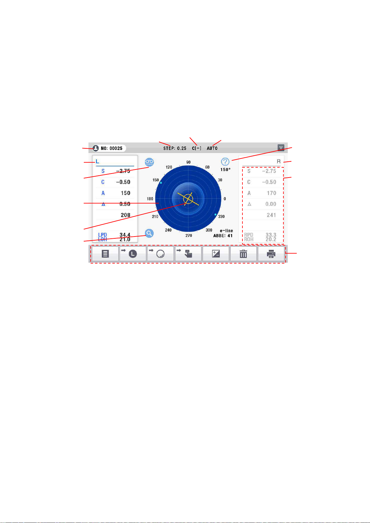
Patient ID
Measurement unit
Measured lens
Lens Type
Measured lens
Cylinder
Auto
Measured data
Concentric
Circle of prism
Target(Cusor)
Touch menu button
Zoom
PD/OH Mode
4.4 Operating panel
4.4.1 Basic operation
Basic operation of the PLM-8000 is performed on the touch panel.
4.4.2 Measurement display
(1) Measured data
Indicates the following data:
S : Spherical value
C : Cylinder value
A : Angle of cylinder shaft
P : Prism value
ADD : Progressive ADD value
RPD, LPD : PD value
(2) Concentric circle of prism
Concentric circles indicates 1 Prism~7Prism respectively.
(3) Measured lens
Indicates whether the lens being measured is a monocle or a right-side/left-side lens.
(4) Cylinder mark
Cylinder mark is indicated as ‘+’, ‘-‘ according to ‘CYLINDER’ of user menu.
(5) Measurement step
Display step of 0.01, 0.06, 0.12, or 0.25.
(6) Auto Measurement
Display whether the measurement is used automatically or manually.
10
Page 19
PLM-8000 Operation Manual
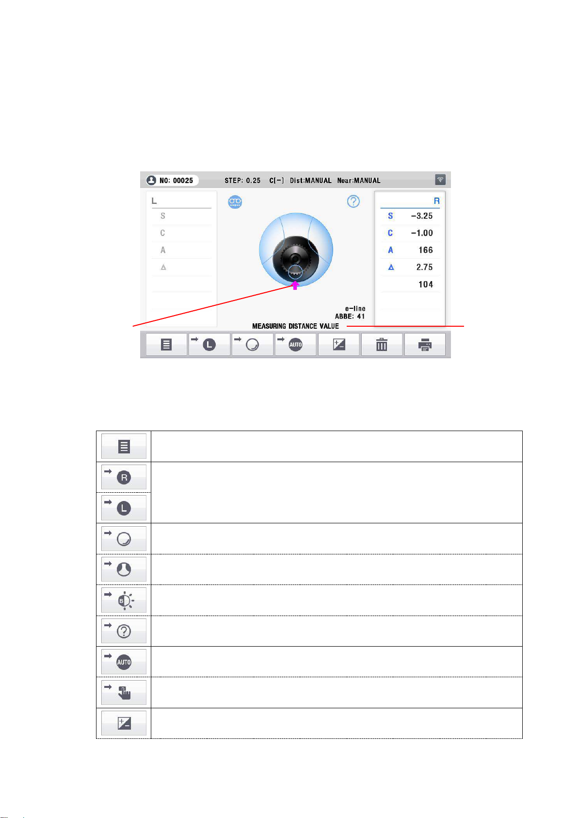
Button for selecting a user setup mode
In case of single lens, you can switch between left and right selection
of the framed lens or you can select left/right lens
Changes the screen to the normal measurement screen.
Changes the screen to the progressive measurement screen.
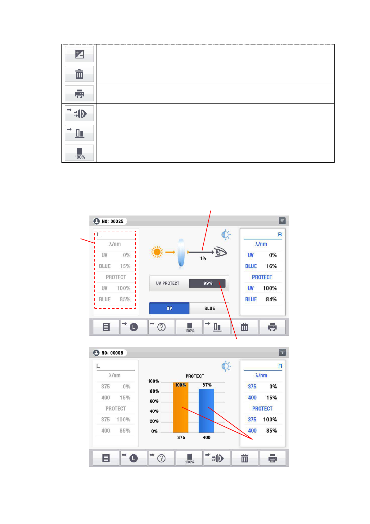
To enter the UV/Blue measurement screen
Changes the screen to the normal measurement screen in auto
measurement.
Press this button in order to automatic measurement
Press this button in order to start manual measurement
Press this button in order to change CYL (-) from.
Progressive
guide line
message
(7) Lens Type
Indicates the type of the lens which is presently being measured.
(8) Progressive guide line
It indicates the location to find near & distance power.
☞ Progressive guide line is displayed only when progressive lenses are measured.
(9) Target
Indicates the optical center of the lens being measured.
(10) Touch button
11
Page 20
PLM-8000 Operation Manual
Press this button in order to change CYL (+) from.
Button for clearing the value of the measured data to ‘0’
Button for print out the measured value
To enter the UV or Blue measurement icon screen
To enter the UV/Blue measurement graph screen
Adjust the current transmission to 100%(UV and BLUE)
1. Measured data
3. Current Protection Ratio
4. Current Protection Height
2. Current Transmission Ratio
4.4.3 UV/BLUE Display
12
Page 21
PLM-8000 Operation Manual
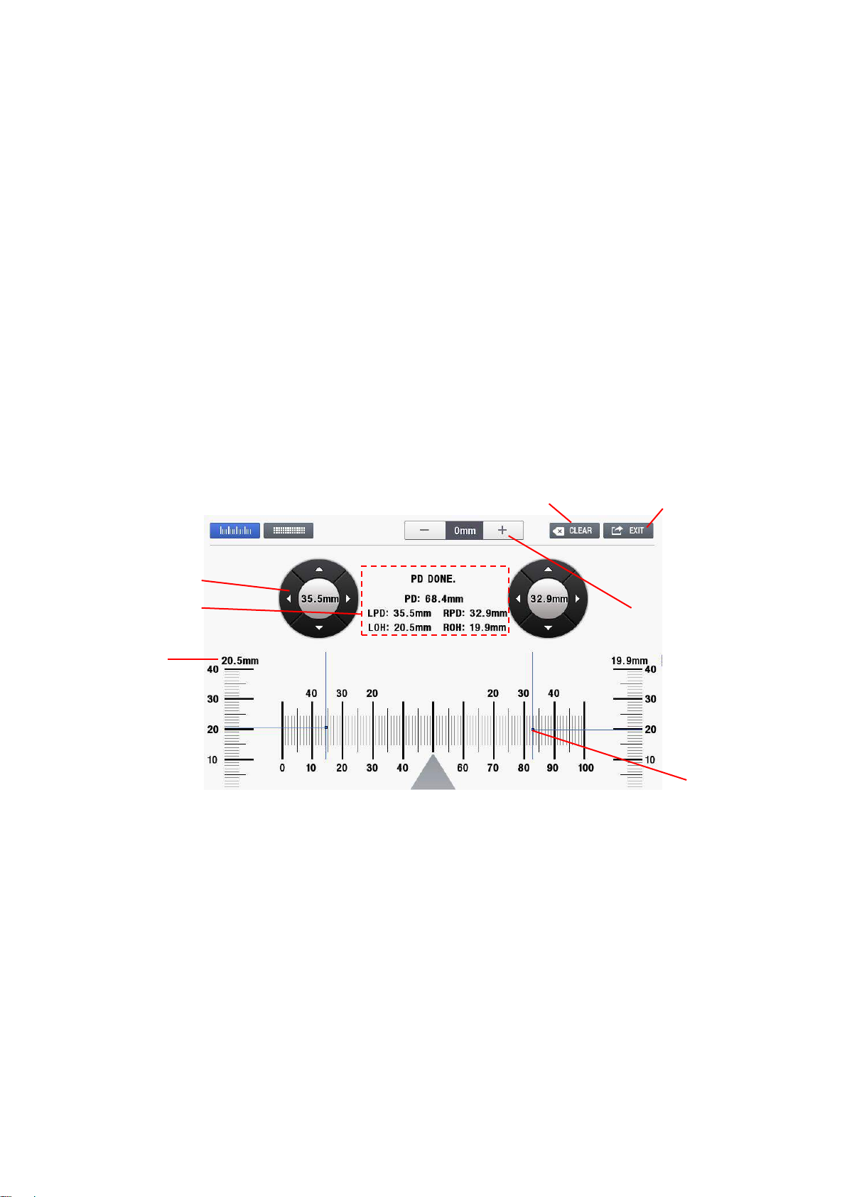
1.Control button
3. Height Value
2.Measured data
6. Adjustment button
4.Clear Button
5.Exit Button
7. Bar position
(1) Measured data
Indicates the following data:
UV : UV transmission value.
BLUE : BLUE transmission value.
Protect UV : UV protect value.
Protect BLUE : BLUE protect value.
(2) Current Transmission Ratio
Display the transmission ratio in a bar graph form.
(3) Current Protection Ratio
UV PROTECT: Display the UV protection ration
BLUE PROTECT: Display the BLUE protection ration
(4) Current Protection Height
Show the height of the current protection.
4.4.4 PD Display
(1) Control button
Four-way arrow buttons adjust the bar position
(2) Measured data : RPD, LPD, ROH, LOH
(3) Height Value
(4) Clear Button
(5) Exit Button
(6) Adjustment button : Glassses frame thickness adjustment button
(7) Bar position
13
Page 22
PLM-8000 Operation Manual
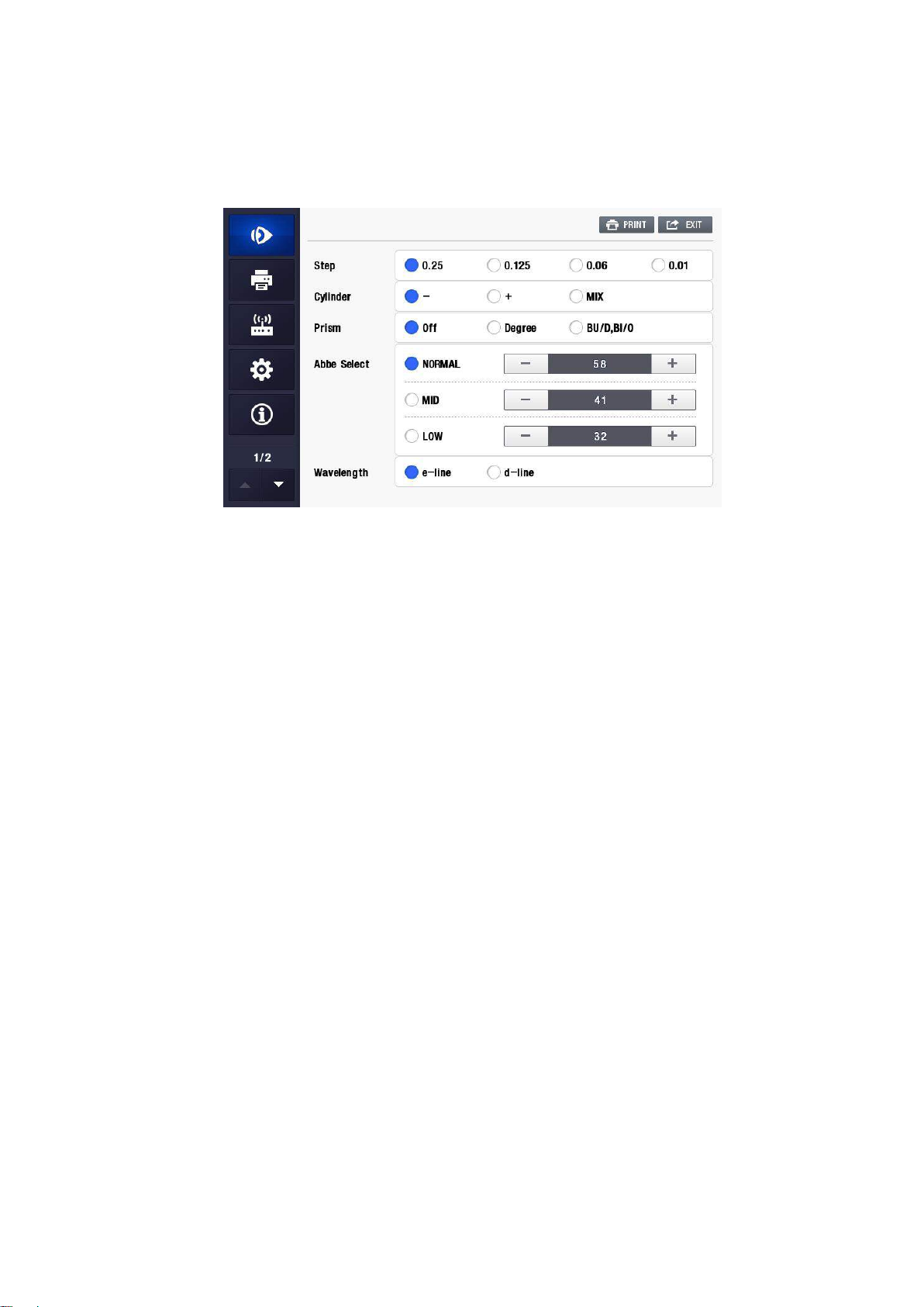
4.4.5 User Setup display
User mode is provided as Touch Screen for users to set-up directly.
(1) STEP
① 0.25 : Display step, 0.25 step
② 0.125 : Display step, 0.125 step
③ 0.06 : Display step, 0.06 step
④ 0.01 : Display step, 0.01 step
(2) CYLINDER
① - : The cylinder reading direction to “-”.
② + : The cylinder reading direction to “+”.
③ MIX : The cylinder reading direction to “+” or “-”.
(3) PRISM
① OFF : No prism display.
② DEGREE : Polar coordinates.
③ BU/D, BI/O: Rectangular coordinates.
(4) Abbe Select (This can be applied to the high-refractive lens.)
① NORMAL : Designated value for NORMAL ABBE(= 50 ~ 60)
② MID : Designated value for MID ABBE(=40~49)
③ LOW : Designated value for LOW ABBE(=30~39)
(5) Wavelength
① e-line : Display the refractive power according to e-line
② d-line : Display the refractive power according to d-line
14
Page 23
PLM-8000 Operation Manual
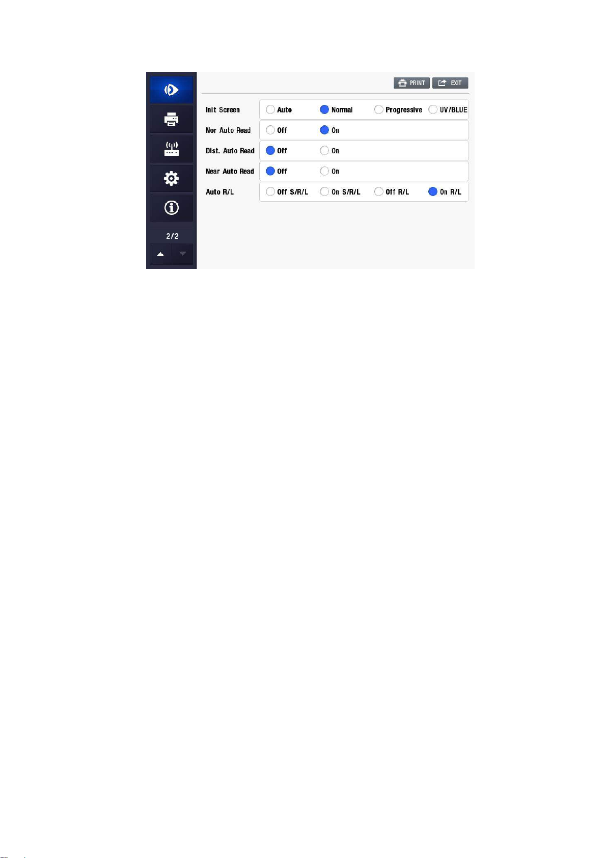
(6) Init Screen
① Auto
When the lens on the lens holder is detected as a progressive addition lens, the
normal measurement screen changes to the PAL measurement screen
automatically.
When the distance portion of a PAL is placed on the lens holder, it is not
detected as a PAL
In such a case, put the intermediate portion(progressive zone) or near portion
area on the lens holder
② Normal : Normal lenses mode
③ Prog : Prograssive lenses mode
④ UV/BLUE : UV / BLUE lenses mode
(7) Nor Auto Read
① OFF : Enable automatic measurement.
② ON : Disable automatic measurement.
☞ Only Using Normal lenses mode.
(8) Far Auto Read
① OFF : Disabling the auto read function for the far portion in measurement of
progressive lenses.
② ON : Enabling the auto read function for the far portion in measurement of
progressive lenses.
(9) Near Auto Read
① OFF : Disabling the auto read function for the near portion in measurement of
progressive lenses.
② ON : Enabling the auto read function for the near portion in measurement of
progressive lenses.
(10) AUTO R/L
① OFF S/R/L : Disable automatic transfer function in case of left/right lens
measurement. Initial screen stands by for single lens measurement.
15
Page 24
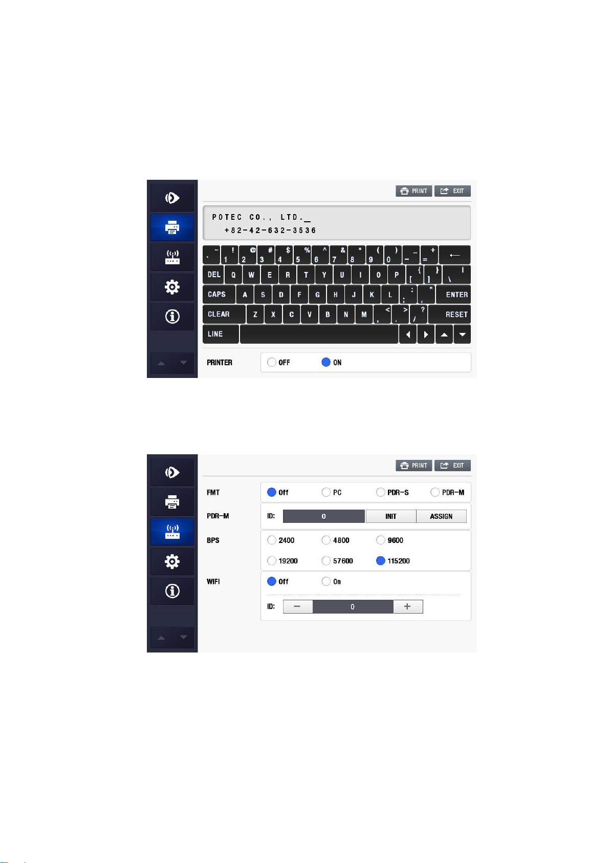
PLM-8000 Operation Manual
② ON S/R/L : Enable automatic transfer function in case left/right lens
measurement. Initial screen stands by for single lens measurement.
③ OFF R/L : Disable automatic transfer function in case of left/right lens
measurement. Initial screen stands by for right lens measurement.
④ ON R/L : Enable automatic transfer function in case left/right lens
measurement. Initial screen stands by for right lens measurement.
(11) PRINTER
① OFF : Not used.
② ON : Print out in the unit of 24 column by means of the internal printer.
(12) FMT
① OFF : Turn off the external communication.
② PC : Turn on the external communication.
③ PDR -S : Turn on the protocol between single PDR-7000.
④ PDR -M : Turn on the protocol between multi PDR-7000.
(13) PDR-M : Setting the multi PDR-7000
16
Page 25
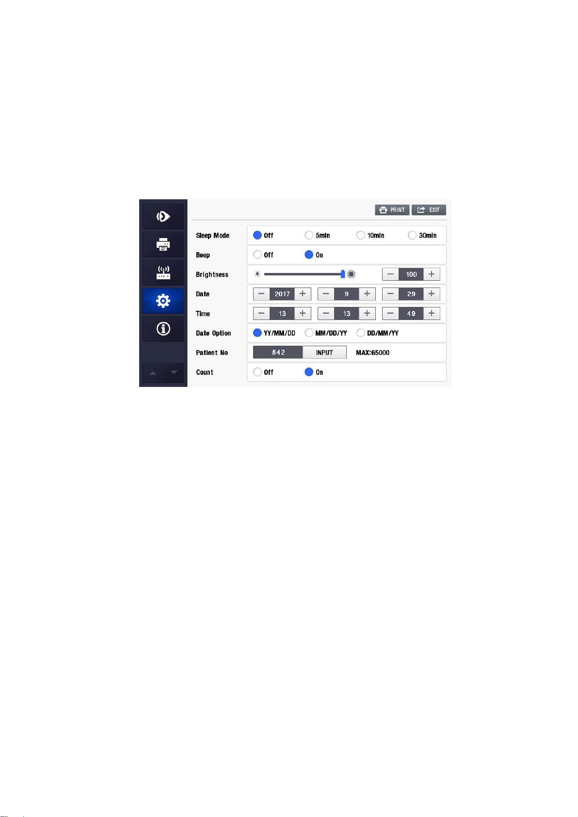
PLM-8000 Operation Manual
(14) BPS
Select the speed of the external communication
① 2400 : communication speed by 2400.
② 4800 : communication speed by 4800.
③ 9600 : communication speed by 9600.
④ 19200 : communication speed by 19200.
⑤ 57600 : communication speed by 57600.
⑥ 115200 : communication speed by 115200.
(15) Sleep Mode
① OFF : Disable Power Save Function.
② 5Min : Enter Power Save Mode if there is no operation by operator for 5
③ 10Min : Enter Power Save Mode if there is no operation by operator for 10
④ 30Min : Enter Power Save Mode if there is no operation by operator for 30
(16) BEEP
① ON : Enable Sound.
② OFF : Disable Sound.
(17) Brightness
Adjust the brightness of LCD.
Pressing ‘+’ or ‘-’ button to adjust the brightness of LCD
(18) Date
Pressing ‘-’ or ‘+’ button renders the related item to be decreased or increased by “1”.
2001 ~ 2099 : Year
01 ~ 12 : Month
01 ~ 31 : Day
minutes.
minutes.
minutes.
17
Page 26
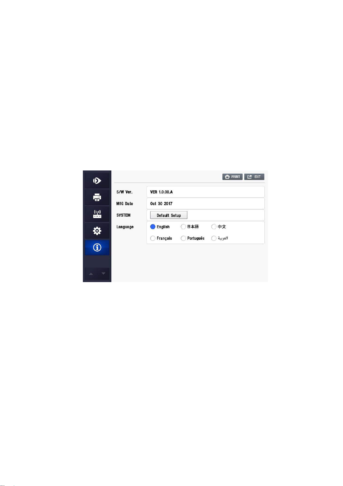
PLM-8000 Operation Manual
(19) TIME
Pressing ‘-’ or ‘+’ button renders the related item to be decreased or increased by “1”.
00 ~ 23 : Hour
00 ~ 59 : Minute
00 ~ 59 : Second
(20) Date Option
Order of displaying the date
(21) Patient No
Setting of the patient number
(22) Count
To select whether using the patient number or not.
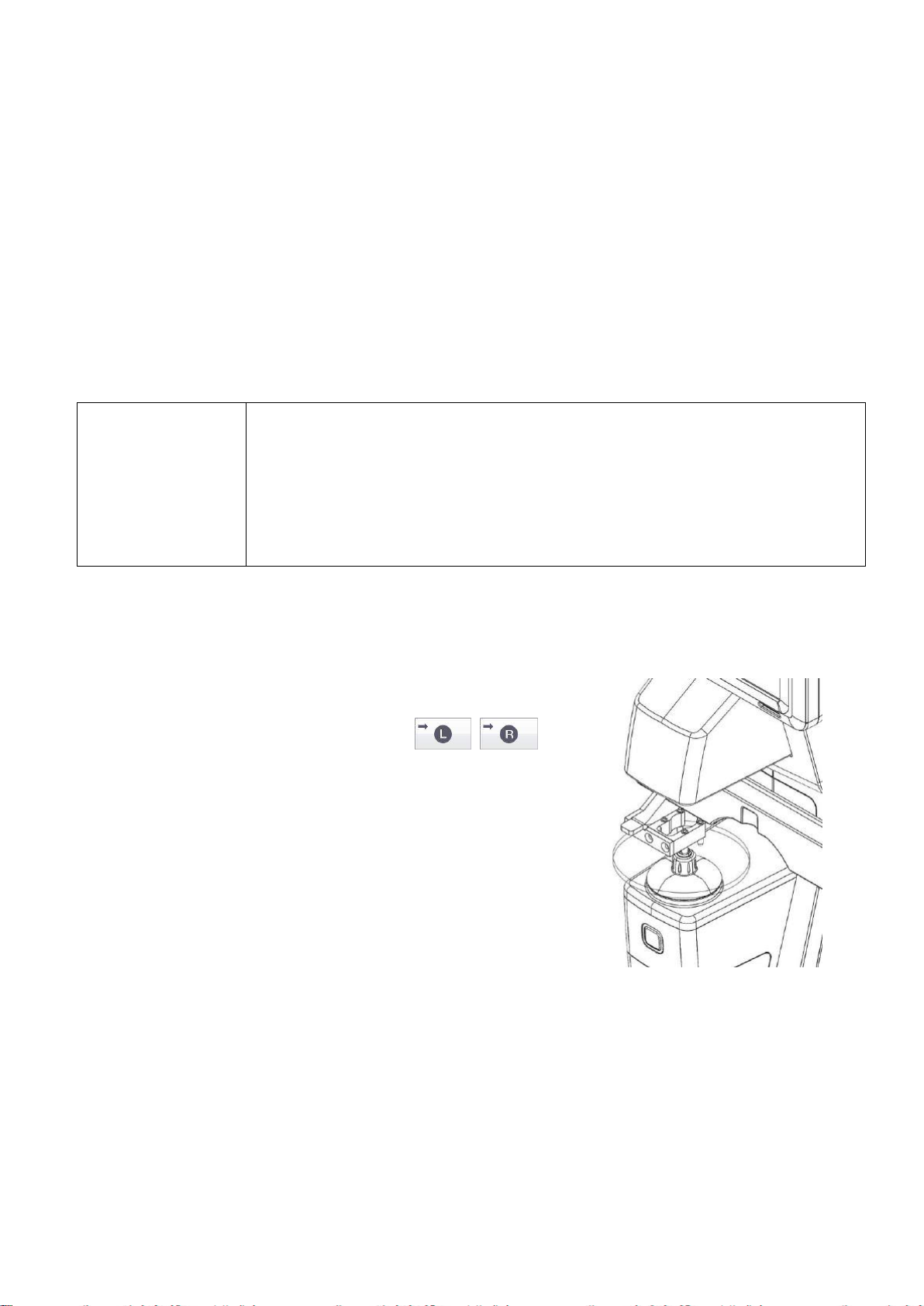
(23) S/W Ver. / MfG Date
It displays the version of the Software that is currently installed in the product.
(24) System
If you press the “Default Setup” button, the system variable will be initialized.
(25) Language
Setting of the Language
18
Page 27
PLM-8000 Operation Manual
WARNING
If any of the following occur, immediately turn OFF the power switch,
unplug the power cable from the AC outlet, and contact the dealer or the
agent who/where you purchase this machine.
When there is smoke, strange odor or abnormal sound.
When liquid has been spilled into the instrument or a metal object has
entered through an opening.
When the product has been dropped or its housing damaged
5. Measurement
5.1 Preparation
(1) Connect the power cable.
(2) Turn ON the power.
☞ Do not turn on the power as the lens is on the lens table or else it is possible to
occur errors as measuring or starting. If ‘Error-Initial Error!!!’ or ‘Setup Data Error’,
‘UV Init Error’, ‘BLUE Init Error’ is seen to the screen, refer the ‘6. Self-diagnosis and
Maintenance’.
5.2 Measuring general lenses
(1) Connect the power cable.
(2) Turn ON the power.
(3) Place the lenses on the nosepiece.
① Press the LR touch button( )
to specify the left-eye lens or the right-eye
lens as necessary.
② Place the lens on the nosepiece with the
convex side up.
(4) Lower the lens retainer.
19
Page 28
PLM-8000 Operation Manual
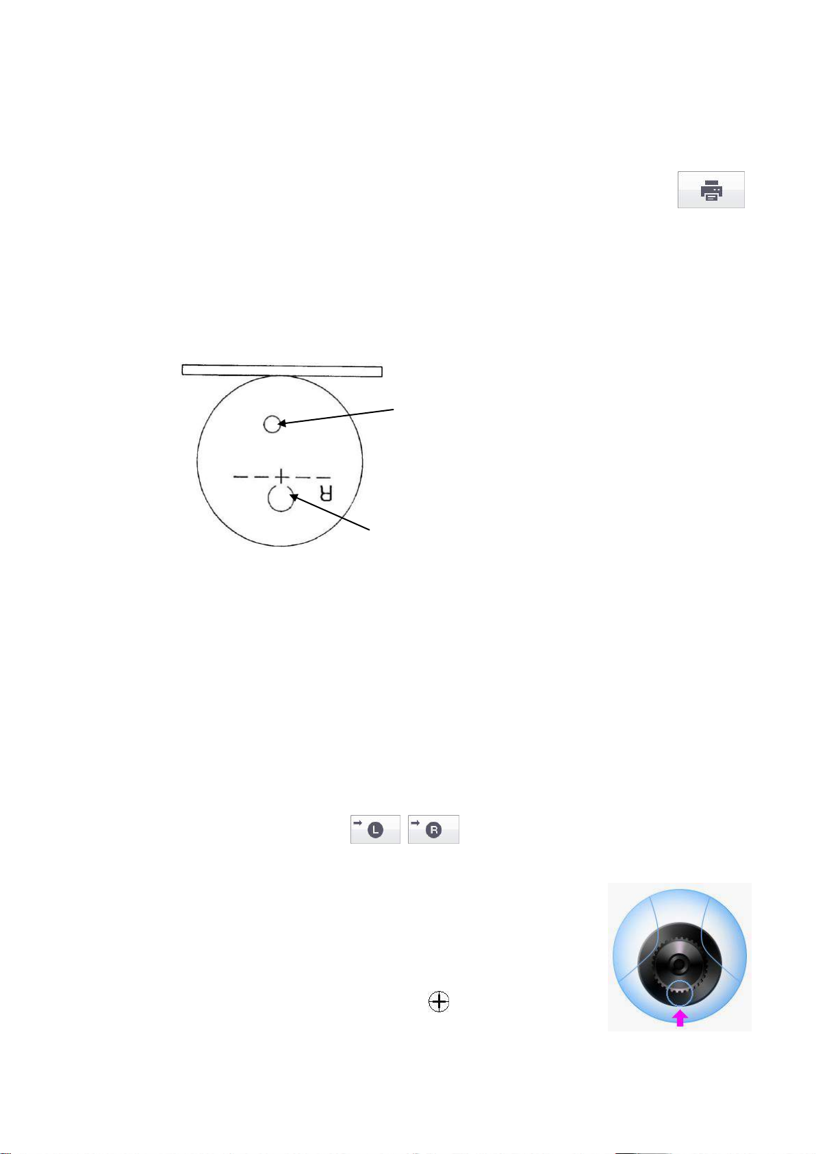
Near Power measuring Position
Far Distance power measuring Position
(5) Adjust the focus.
(6) Press the read button to store the measured value.
(7) Raise the lens retainer, and place the other lens on the nosepiece.
(8) Adjust the focus.
(9) Press the read button to store the measured value. Press the Print button( )
to print out the measured value.
5.3 Measuring multi-focal lenses
5.3.1 Structure of the progressive power lens
5.3.2 Measuring progressive power lenses
* Basic setup mode : Dist. Auto Read – “Off” and Near Auto Read – “Off”
* How to setup Dist Auto Read On/Off and Near Auto Read On/Off : Refer to “4.4.5 User
setup display” on page 15.
(1) Connect with power cable.
(2) Turn on the power supply
(3) Switch to progressive mode from user setting screen mode(Press progressive button
on the normal measurement screen)
(4) Arrange lens.
① Press the LR touch button( ) to specify the left-eye lens or the
right-eye lens as necessary.
② Place the lens on the nosepiece with the convex side up.
(5) Find far distance portion of lens as in the picture shown beside.
① Move lens up/down/left/right for the indicated lens in far
distance portion to be adjusted to the center of cross.
② If lens is on the indicated place, beep sound is heard and
measurement works.
③ If far distance portion is discovered, mark is shown
temporarily.
☞ In case of the far distance portion is not properly discovered, press read button
when far distance portion power is small regardless of cursor location.
20
Page 29
PLM-8000 Operation Manual
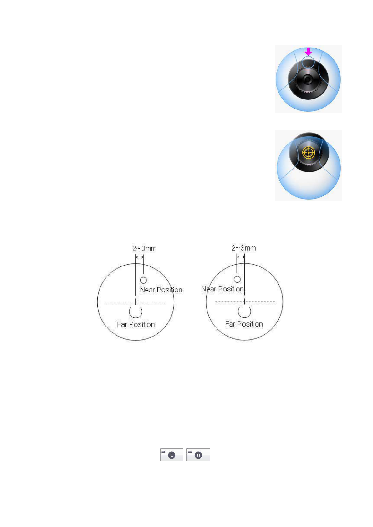
(6) If the far distance portion is discovered, indication of lens
cursor will show to find the location of near portion and ADD
value is presented on screen.
(7) Save measured value by pressing read button. If exterior
printer is supported.
☞ In case of bottom frame of near distance portion is cut out,
adjacent or lens area is connected after the center of near
distance portion, maintain lens table and confirm the power by
pressing read button when the power is at the maximum.
☞ When measuring the left lens, the lens moves to the right about 2 ~ 3mm or When
measuring the left lens, the lens moves to the right about 2 ~ 3mm the more accurate
measurement can be measured.
Left Lens Right Lens
5.3.3 Measuring Bifocal / Trifocal Lenses
(1) Connect the power cable.
(2) Turn ON the power.
(3) Switch to progressive mode from user setting screen mode(Press progressive button
on the normal measurement screen)
(4) Place the lenses on the nosepiece.
① Press the LR touch button( ) to specify the left-eye lens or the
right-eye lens as necessary.
② Place the lens on the nosepiece with the convex side up
21
Page 30
PLM-8000 Operation Manual
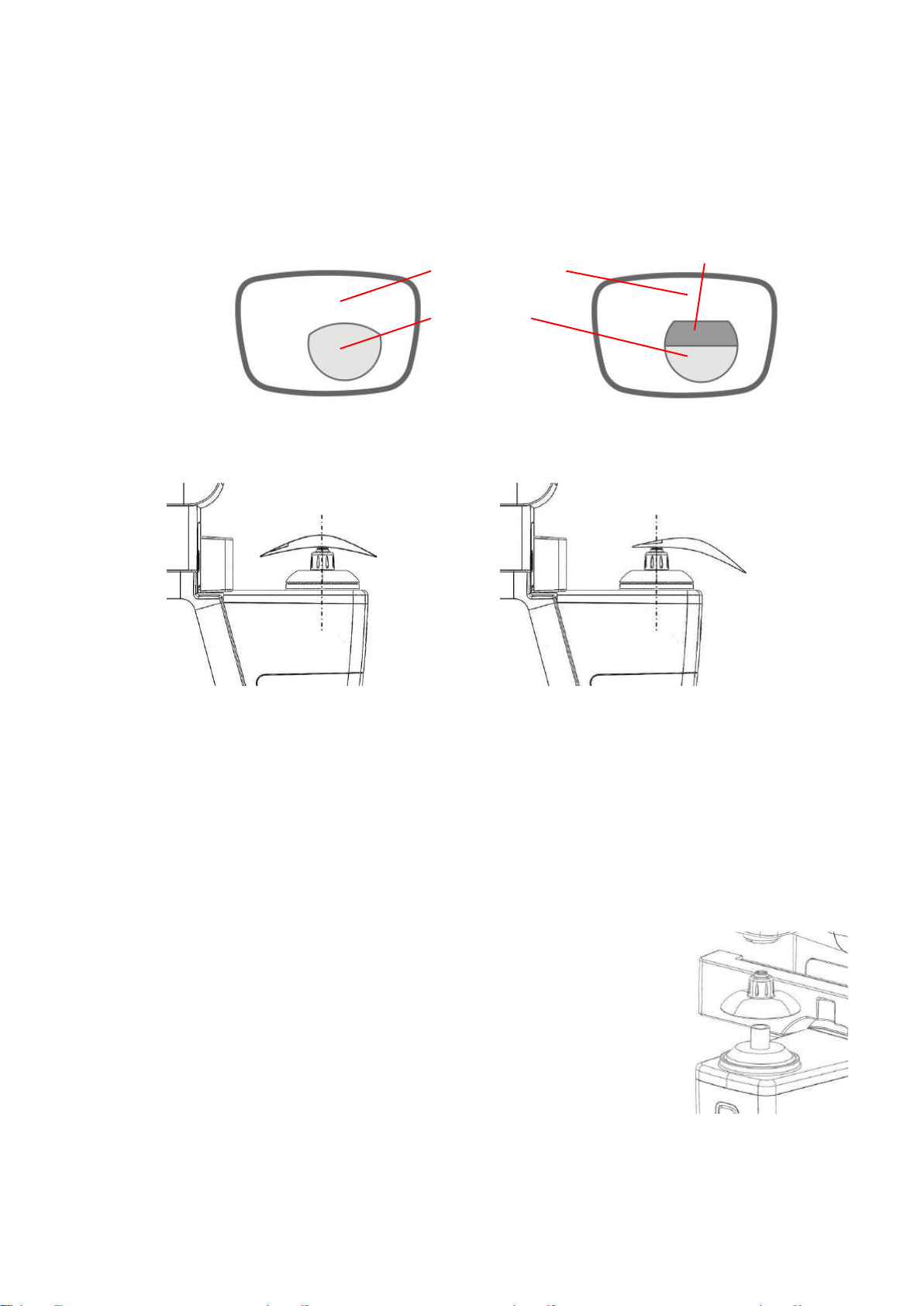
Near portion
Distance portion
Intermediate portion
(5) Find the Far distance portion of the lens as shown in the following figure. Mostly the
optical center of lenses is the Far distance portion of the lenses.
(Bifocal Lens: Distance portion Near portion)
(Trifocal Lens: Distance portion Intermediate portion Near portion)
(6) After finding the Far distance portion of the lens, pull down the lens then ADD value
will show up if the near distance portion of the lens is found.
(7) Press the read button to store the measured value. Press the Print button to print out
the measured value.
5.4 Measuring contact lenses
(1) Connect the power cable.
(2) Turn ON the power.
(3) Replace the nosepiece with the nosepiece for contact lens.
(4) Place the lenses on the nosepiece.
(5) Adjust the focus.
(6) Press the read button to store the measured value.
(7) Press the Print button to print out the measured value.
① Press the LR touch button to specify the left-eye lens or
the right-eye lens as necessary.
② Place the lens on the nosepiece with the convex side up.
22
Page 31
PLM-8000 Operation Manual
5.5 Measuring UV / BLUE
(1) Connect the power cable.
(2) Turn ON the power.
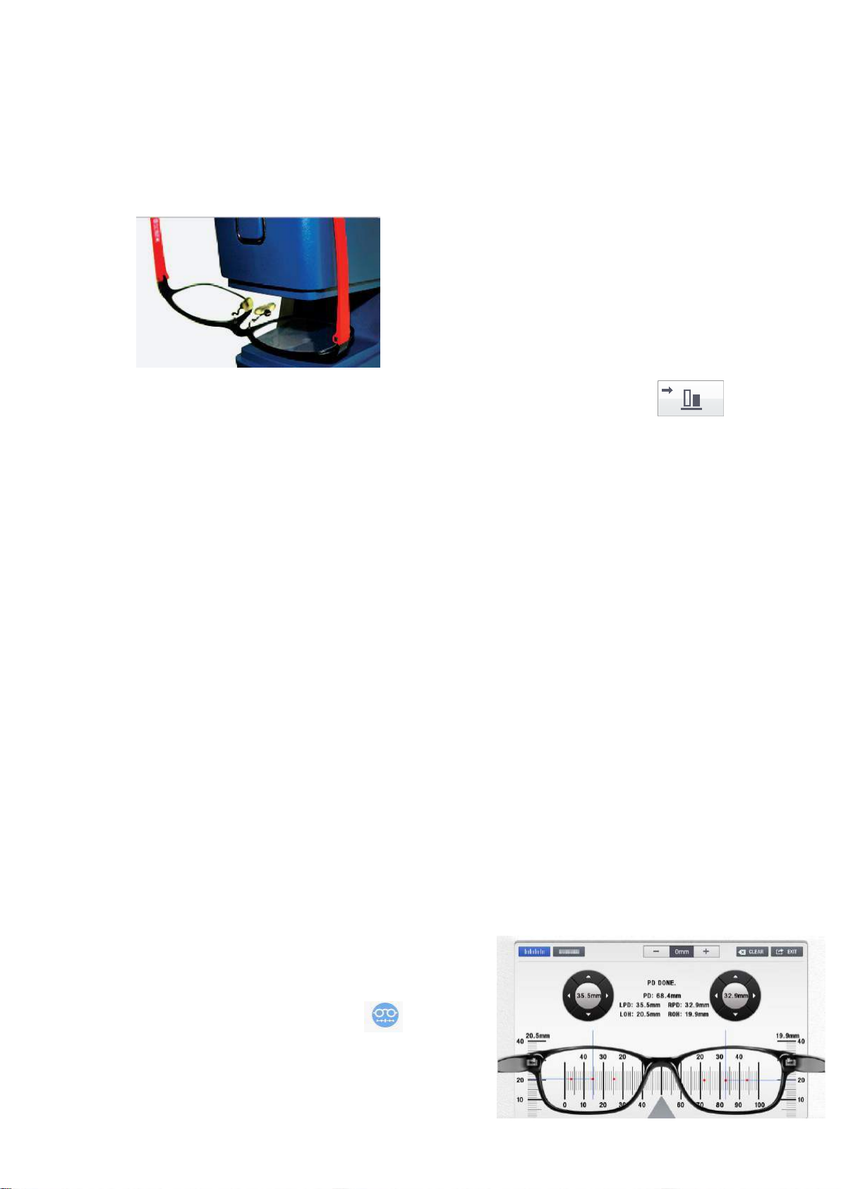
(3) Take out UV, BLUE cover and put in the lens of glasses like the below picture
(4) Press the read button to store the measure value.
When measuring UV, BLUE at the same time, click the graph button
then the bar graph is seen on the screen
5.6 Measuring prismatic lenses
(1) Connect the power cable.
(2) Turn ON the power.
(3) Place the lenses on the nosepiece.
① Press the LR touch button to specify the left-eye lens or the right-eye lens as
necessary.
② Place the lens on the nosepiece with the convex side up.
(4) Lower the lens retainer.
(5) Change the prism indication type on the basis of the prism type (X-Y(BU/D,BI/O), P-
B(polar coordinates: angle) indicated on the prescription.
(6) Adjust the focus.
(7) Press the read button to store the measure value.
(8) Mark using the marking lever.
(9) Raise the lens retainer, and place the other lens on the nosepiece.
(10) Adjust the focus.
(11) Press the read button to store the measured value. Press the Print button to print out
the measured value.
5.7 Measuring PD / OH
(1) Connect the power cable.
(2) Turn ON the power.
(3) Pull down the LCD as much as possible
(4) Click the glasses shaped icon
(5) Put the marked lens on the LCD
(6) Adjust it with the +, - icon in the light of a
thickness of a glass frame
23
Page 32
PLM-8000 Operation Manual
External device connection connector
CAUTION
When user connected external optometric equipment , determine the
pin number of connectors.
Recommended Products : Optometry equipment of POTEC
(PRK-7000, PRK-8000, PDR-7000).
USB port to upgrade the system's specifications for the terminal.
Service personnel will be used.
! NOTE
! NOTE
(7) Align the horizontal and vertical bar with the both sides abstract point by using the
direction indicator button
(8) Press the read button to store the measure value.
(9) Press the EXIT button
(10) Press the Print button to print out the measured value
5.8 Power-saving mode
The power-saving mode is activated if no operation(Not operated read button and touch) or
no measure is carried out for approximately 5 minutes, 10 minutes, 30 minutes in the
measurement mode. In the power-saving mode, the READY lamp flickers. If pushing the
Read button or touch, it is returned to the measurement mode in the power-saving mode.
5.9 Connection with external optometry equipment
Using an external connection socket, can be connected with external optometry equipment.
The external optometry equipment of the POTEC are connected by connector cable which
be provided from POTEC.
(1) Connect on the printer socket of the left side on the real bottom to a 6-pin connector
cable which be provided from Potec.
(2) Connector cable to connect to the external device.
(3) Measured the Lens.
(4) Click the printer button in the menu.
24
Page 33
PLM-8000 Operation Manual
Message
Cause
Measure
ERROR – Initial Error !!!
Product initialization error
Please check on the Lens holder
Setup Data Error
UV Setup Error
BLUE Setup Error
Trouble of Data in Product
Contact an authorized supplier
UV Init Error
BLUE Init Error
Product initialization error
Check whether something is on
the UV, BLUE sensor or not
Message
Cause
Measure
ERROR
Optical problems
Please check on the Lens holder
PDR-7000 Com Error!!
Communication cable issue
Check the connecting status of
the communication cable
Out of Range !!!
The lens is out of the physical
measurement range
Place the lens on the center of
the lens support
GUI Upload Error
GUI SD card faulty
Contact an authorized supplier
SPH > +27D, SPH < -27D
Sphere value exceeds±27D
Check the power of the lens.
CYL > +11D, CYL < -11D
Cylinder value exceeds±11D
Check the power of the lens.
ADD > +11D
ADD value exceeds 11D
Check the power of the lens.
Prism > 21
The lens with the prism value
exceeding 21△is on the nosepiece.
Check the power of the lens.
PRINTER PAPER
EMPTY!
The print button was pressed with
no printer paper set.
Fill the printer paper.
6. Self-diagnosis and Maintenance
6.1 Before contacting the service personnel
When the instrument operates abnormally or malfunctions, a warning message will appear
on the display.
In this case, take the following measures.
When the instrument does not work properly even after the following measures are taken,
turn OFF the instrument, and contact an authorized supplier.
(1) Message when the power is turned on
(2) Message during measurement
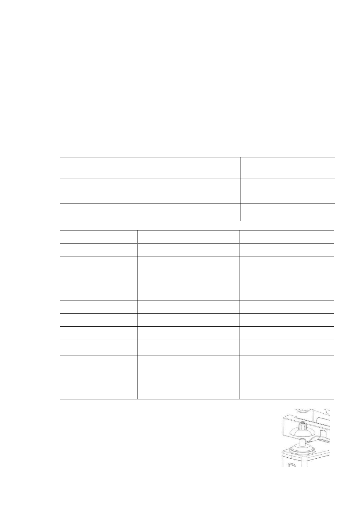
(3) In case of abnormal measured value without mark of measured
message.
It is the case of dust or alien substances under the lens holder.
To handle such case, measure after reinstalling the lens holder
when dust or alien substances are all removed. Please contact to
sales agency if the problem continuously occurs.
25
Page 34
PLM-8000 Operation Manual
When a red line appears on the side of the printer paper, it means that the paper is running
short.
In such a case, stop using the printer and replace the roll with a new one.
NOTE
Do not run the printer while the printer paper is not set. It may damage
the printer head.
Do not pull the paper in the printer forcefully. This may cause
malfunction of the printer.
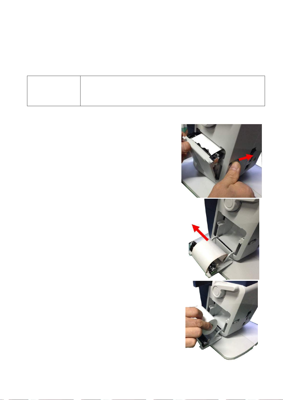
(1) Slide the printer cover lever at the rear of the
device to open the cover.
(2) Take out the used printer paper.
(3) Set the new printer paper..
6.2 Replacing Print paper
26
Page 35
PLM-8000 Operation Manual
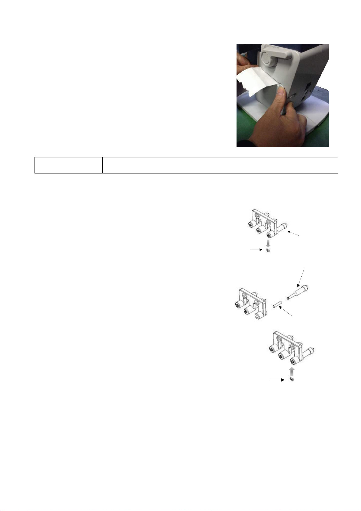
(4) Press the right and left sides of the printer cover to
close the printer.
CAUTION
Be careful not to touch the printer head inside the device.
(1) Remove the c-ring with tweezers.
(2) Remove the ink cartridge.
Ink cartridge
C-ring
(3) Insert the spring into the holder.
(4) Insert the new Ink cartridge into the holder.
Ink cartridge
Spring
(5) Set the c-ring again.
C-ring
(1) Basically keep the instrument clean. Do not use highly volatile materials, such as
thinner, benzene, etc.
(2) Sprinkle a little liquid soap on soft cloth, squeeze the water from the soft cloth, and
clean the parts of the instrument.
6.3 Replacing Ink cartridge
6.4 Cleaning the device
27
Page 36
PLM-8000 Operation Manual
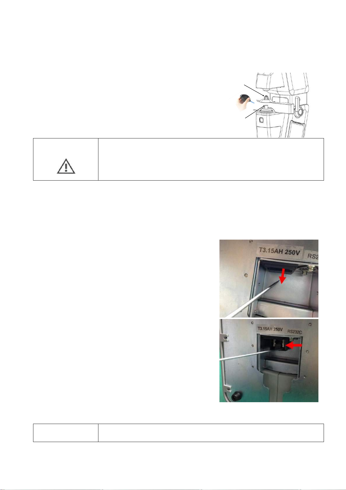
(1) Remove the lens holder
(2) Clean the cover glass.
Cover glass
Lens holder
CAUTION
Clean the cover glass under the lens holder with the Hand Air Blower.
The dust on the cover glass may be sharp particles. If you wipe without
an air blower, the coating on the cover glass may scratch. This has the
risk of affecting the measured value.
Carefully remove the dust.
(1) Turn off the device
(2) Remove the power cord
(3) Open the fuse case
It is easy to work with a flat screwdriver
(4) Remove the old fuse and put in the new one
(5) Close the fuse case
CAUTION
To avoid risk of electric shock, always disconnect the plug from the
system prior to fuse replacement.
6.5 Cleaning the cover glass
6.6 Fuse Replacement
28
Page 37
PLM-8000 Operation Manual
WARNING
Arbitrary Replacement of a component by customer could result in an
unacceptable risk.
CAUTION
This instrument incorporates a lithium battery, which may pollute the
environment if the instrument is abandoned.
Please ask a professional waste disposal company to handle
disposal, or contact a POTEC representative or distributor before
disposing of the instrument.
6.7 Service Information
(1) Repair
If problems cannot be solved even after taking the measures indicated in section 5.1,
contact a POTEC representative or distributor for repair.
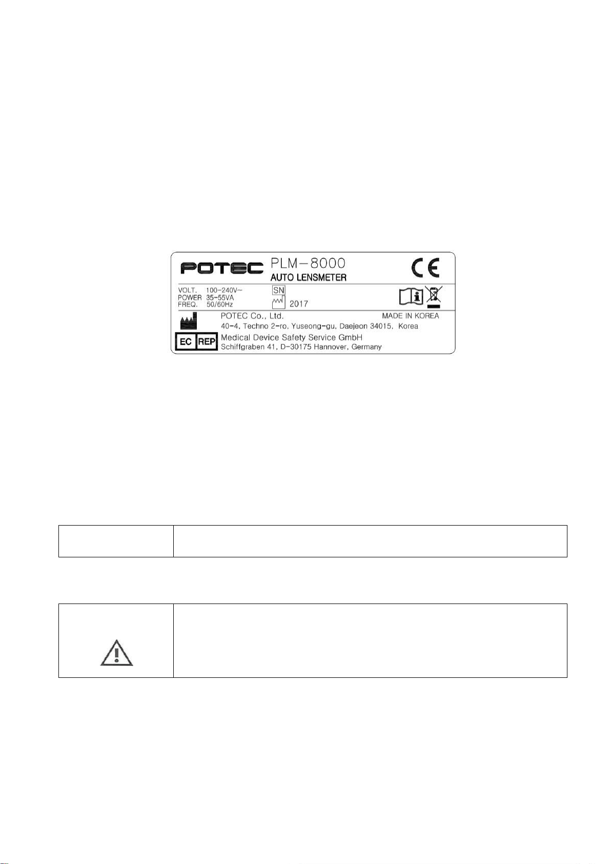
Inform them of the following information, which is indicated on the nameplate of the
instrument.
Product Name : PLM-8000
Serial Number : Seven characters indicated on the nameplate
Problems : Detailed description is appreciated.
(2) Product Cycle of calibration
Calibration (required to maintain the functioning of the product) of this product do not
during normal performance. But, Basic lens (required necessary of product) of
manufacture must do test and calibration.
(3) Other’s Information
Upon required repair of component in product, circuit diagrams, component part lists,
descriptions, calibration instructions, or other information will be provided to assist
service personnel to repair parts.
(4) Disposal of product
29
Page 38

PLM-8000 Operation Manual
Measurement
Sphere power(SPH)
-25D ~ +25 D (0.01 / 0.06 / 0.12 / 0.25 D steps)
Cylinder power(CYL)
0D ~ ±10 D (0.01 / 0.06 / 0.12 / 0.25 D steps)
Axis(AX)
0˚ ~ 180˚ (1˚ step)
Addition power
0 ~ +10 D (0.01 / 0.06 / 0.12 / 0.25 D steps)
Prism power
0 ~ 20 ∆
Transmittance(UV, Blue)
0 ~ 100%
Measurement Mode
Cylinder Mode
-, +, MIX
Prism Mode
Rectangular / Polar
Display
7.0 inch TFT COLOR LCD Monitor, Touch
Wave
e-line, d-line
Abbe value
30 ~ 60
Others
LED wavelength
525nm, 375nm(UV), 400nm(BLUE)
Lens diameter
Max. approx. 120 mm
Marking system
Ink Cartridge type
Interface
RS-232C, USB
Printer
Thermal line printer with auto cutter
Rated Voltage
100-240V~, 50/60Hz
Power consumption
15-53VA
Size
198(W) 245(D) 420(H) mm
Weight
Approximately 5kg (only equipment)
Environment conditions
In use
Temperature : +10℃ ~ +40℃
Humidity : 30% ~ 90% RH
7. Specification
7.1 Specifications
30
Page 39

PLM-8000 Operation Manual
Pressure : 80 ~ 106 kPa
In storage
(non packaging)
Temperature : -10℃ ~ +55℃
Humidity : 10% ~ 95% RH
Pressure : 70 ~ 106 kPa
In transport & storage
(packing)
Temperature : -40℃ ~ +70℃
Humidity : 10% ~ 95% RH
Pressure : 50 ~ 106 kPa
7.2 Components
Operation manual ·················································································· 1
Contact lens support··············································································· 1
Power cable ························································································· 1
Dust cover ··························································································· 1
31
 Loading...