


 RV2600 DTS
AV Digital Home Theater Receiver
OWNER’S MANUAL

CAUTION Regarding Placement
To maintain proper ventilation, be sure to leave a space around the unit (from the largest outer dimensions including projections) equal to, or greater than, shown below.
Left and Right Panels: 10 cm
Rear Panel |
: 10 cm |
Top Panel |
: 50 cm |
Contents
Thank you for choosing TEAC. Read this manual carefully to get the best performance from this unit.
Contents . . . . . . . . . . . . . . . . . . . . . . . . . . . . . . . . . . . . . . . . . 2 Before Use . . . . . . . . . . . . . . . . . . . . . . . . . . . . . . . . . . . . . . . 3 How to Reset the Settings to the FACTORY DEFAULTS . . . . 3 Connection (FM antenna) . . . . . . . . . . . . . . . . . . . . . . . . . . . . 4 Connection (AM antenna) . . . . . . . . . . . . . . . . . . . . . . . . . . . . 5 Connection . . . . . . . . . . . . . . . . . . . . . . . . . . . . . . . . . . . . . . . 6 Speaker Connections . . . . . . . . . . . . . . . . . . . . . . . . . . . . . . 10 Positioning of the Speakers. . . . . . . . . . . . . . . . . . . . . . . . . . 11 Names of Each Control . . . . . . . . . . . . . . . . . . . . . . . . . . . . . 12 Battery Installation . . . . . . . . . . . . . . . . . . . . . . . . . . . . . . . . . 15
Speaker Configuration. . . . . . . . . . . . . . . . . . . . . . . . . . . . . . 16 Basic Operation . . . . . . . . . . . . . . . . . . . . . . . . . . . . . . . . . . . 20 Dubbing from VIDEO 2 or 3 to VIDEO 1 . . . . . . . . . . . . . . . . 24 Dubbing the audio and video signals separately . . . . . . . . . . 24
Surround Mode . . . . . . . . . . . . . . . . . . . . . . . . . . . . . . . . . . . 25
DOLBY PRO LOGIC IIx MUSIC parameters . . . . . . . . . . 29
Dynamic Range Compression. . . . . . . . . . . . . . . . . . . . . . . . 30
Tuner . . . . . . . . . . . . . . . . . . . . . . . . . . . . . . . . . . . . . . . . . . . 31
Preset Tuning . . . . . . . . . . . . . . . . . . . . . . . . . . . . . . . . . . . . 32
RDS . . . . . . . . . . . . . . . . . . . . . . . . . . . . . . . . . . . . . . . . . . . . 34
RDS Search. . . . . . . . . . . . . . . . . . . . . . . . . . . . . . . . . . . . . . 35
PTY Programs . . . . . . . . . . . . . . . . . . . . . . . . . . . . . . . . . . . 36
Troubleshooting. . . . . . . . . . . . . . . . . . . . . . . . . . . . . . . . . . . 37
Specifications . . . . . . . . . . . . . . . . . . . . . . . . . . . . . . . . . . . . 38
“DTS”, “DTS-ES” and “Neo:6” are trademarks of Digital Theater Systems, Inc.
Manufactured under license from Dolby Laboratories. “Dolby”, “Pro Logic” and the double-D symbol are trademarks of Dolby Laboratories.
CAUTION
The product shall not be exposed to dripping or splashing and that no object filled with liquids, such as vases, shall be placed on the product.
Do not install this equipment in a confined space such as a book case or similar unit.
2
Before Use
Read this before operation
•As the unit may become warm during operation, always leave sufficient space around the unit for ventilation.
The ventilation holes should not be covered. Make sure there is at least 50 cm of space above and at least 10 cm of space on each side of the unit. Do NOT place anything on top of the unit.
•The voltage supplied to the unit should match the voltage as printed on the rear panel. If you are in any doubt regarding this matter, consult an electrician.
•Choose the installation location of your unit carefully. Avoid placing it in direct sunlight or close to a source of heat. Also avoid locations subject to vibrations and excessive dust, heat, cold or moisture.
•Do not place the unit on the amplifier/receiver.
•Do not open the cabinet as this might result in damage to the circuitry or electrical shock. If a foreign object should get into the unit, contact your dealer or service company.
•When removing the power plug from the wall outlet, always pull directly on the plug, never yank the cord.
•Do not attempt to clean the unit with chemical solvents as this might damage the finish. Use a clean, dry or slightly damp cloth.
•Keep this manual in a safe place for future reference.
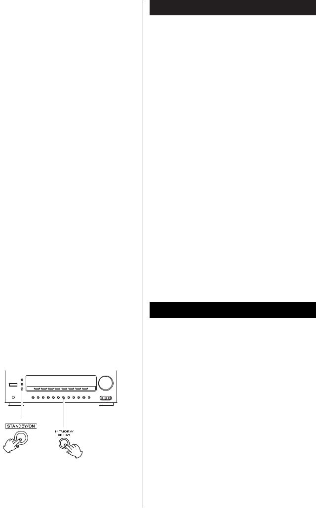
How to Reset the Settings to the FACTORY DEFAULTS
Memory Backup
If the power supply is interrupted for 14 days or longer, the settings kept in memory (such as preset stations and speaker settings) will be erased.
Restoring factory settings
If you have made a lot of changes to the setup, and want to restart from a known set of options, restore the unit to the factory settings as follows:
1.With the unit in the standby mode, briefly press the STANDBY/ON switch while holding down the MEMORY/ENTER button.
•Release the MEMORY/ENTER button immediately after pressing the STANDBY/ON switch.
The model name, etc. appears on the display.
2.Press the MEMORY/ENTER button. The unit turns standby.
3.Press the POWER switch to turn the unit off.
All memories are erased, and the unit returns to the factory settings.
3
A
B
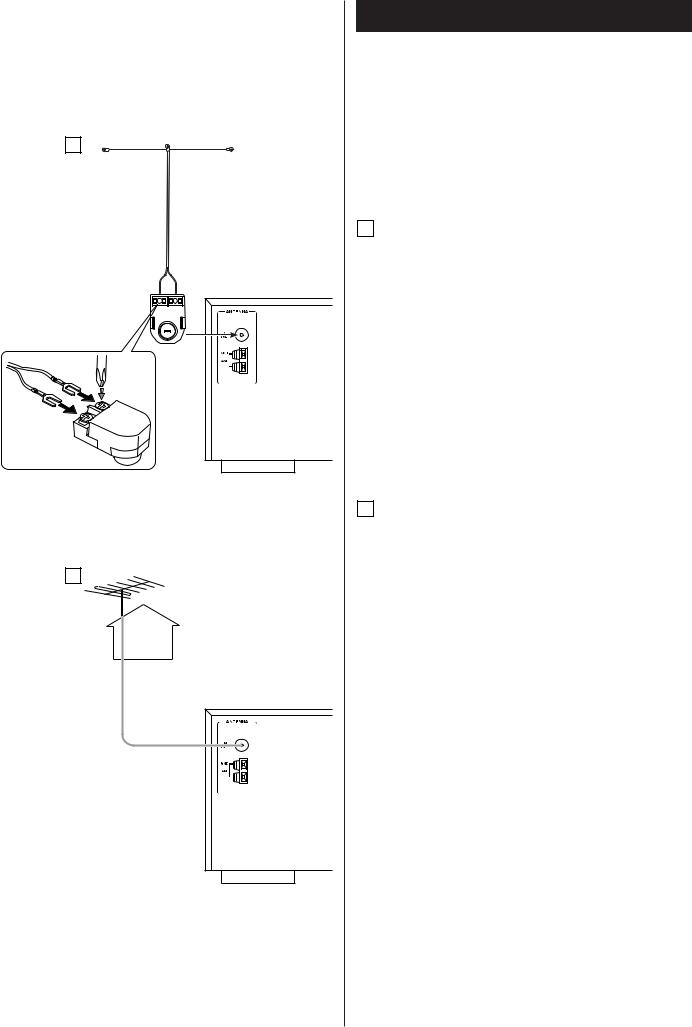
Connection (FM antenna)
CAUTION:
•Switch off the power to all equipment before making connections.
•Read the instructions of each component you intend to use with this unit.
•Be sure to insert each plug securely. To prevent hum and noise, avoid bundling the signal interconnection cables together with the AC power cord or speaker cables.
A FM Indoor Antenna
In an area with strong FM signals, the T-type FM antenna provided with this unit is sufficient.
Extend the antenna into a “T” shape and connect the two wires at the base of the “T” to the provided matching transformer, as shown.
After completing connection, plug the transformer into the “FM 75Ω” socket. Extend the top of the “T” and tune the tuner to your favorite station (see page 31). Adjust the antenna in a suitable location like a window frame or wall until the reception is best and then affix the antenna in that position using thumb tacks, push pins or any other suitable means.
B FM Outdoor Antenna
In an area where FM signals are weak, it will be necessary to use an 75-ohm unbalanced-type outdoor FM antenna. Generally, a 3-element antenna will be sufficient; if you live in an area where the FM signals are particularly weak, it may be necessary to use one with 5 or more elements.
•Disconnect the FM indoor antenna when using an outdoor antenna.
4
AM Outdoor Antenna
Antenne AM extérieure
Antena exterior AM
AM Loop Antenna
Antenne-cadre AM intérieure
Antena de cuadro de AM interior
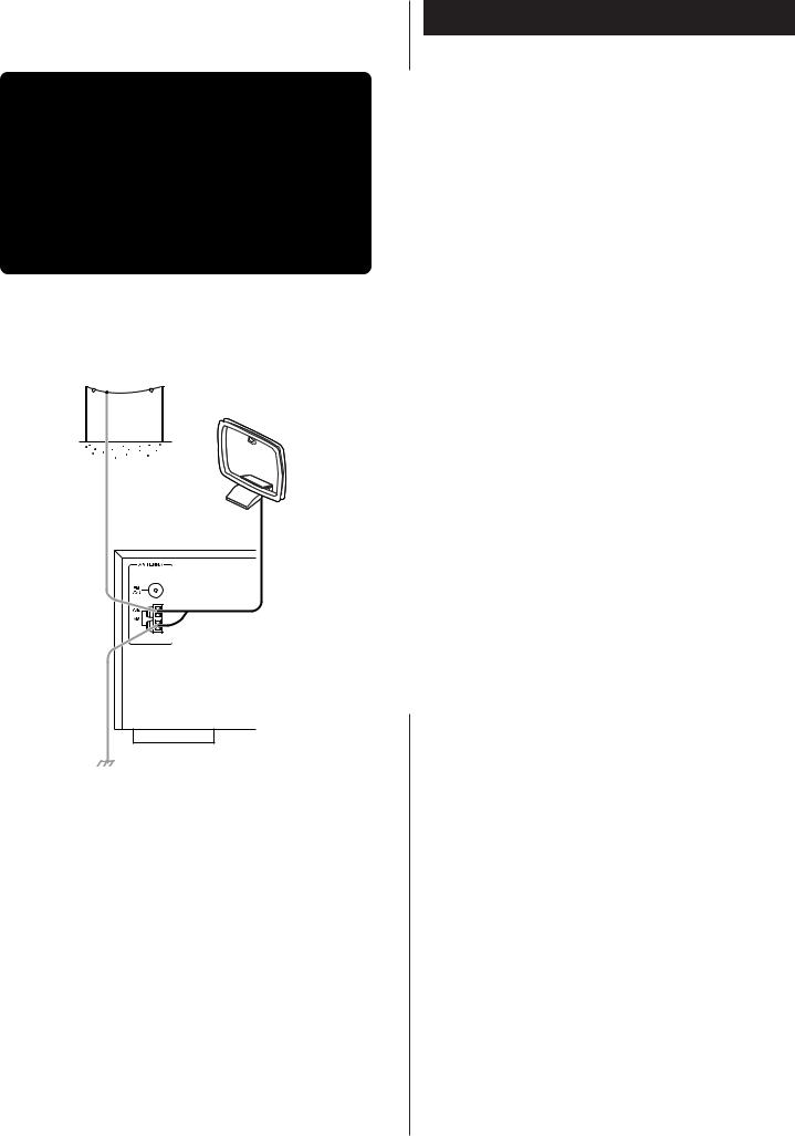
Connection (AM antenna)
AM Indoor Loop Antenna
The high-performance AM loop antenna provided with this unit is sufficient for good reception in most areas.
To stand the loop antenna on a surface, fix the claw to the slot in the antenna base.
Connect the loop antenna’s wires to the AM antenna terminals.
How to connect:
Press the lever, insert the end of the cord, then release the lever. Make sure it is fastened securely by pulling the cord lightly. Make sure only the bare, stripped wire is inserted in the jack and that no plastic insulation is preventing contact between the antenna wire and terminal.
Place the antenna on a shelf or hang it on a window frame, etc., in the direction which gives the best reception. Keep all other wires such as power cords, speaker wires or interconnect wires as far away as possible from the antenna.
•If the AM loop antenna provided does not deliver sufficient reception (often due to being too far from the transmitter or in a concrete building, etc.), it may be necessary to use an outdoor AM antenna.
Use either a high quality commercial AM antenna or, if not available, an insulated wire more than 5 m long, strip one end, and connect this to the terminal as shown.
The antenna wire should be strung outdoors or indoors near a window. For better reception, connect the GND terminal to a reliable ground.
Note:
Even when using an outdoor AM antenna, do not disconnect the AM loop antenna.
5
|
|
|
|
|
|
|
|
|
|
|
|
|
|
|
|
|
|
|
|
|
|
|
|
|
Connection 1 |
|
|
|
|
|
|
|
|
|
|
|
|
|
|
|
|
|
|
|
|
|
|
|
|
|
|
|
|
|
|
|
|
|
|
|
|
|
|
|
|
|
|
|
|
|
|
|
|
|
|
|
|
|
|
|
|
|
|
|
|
|
|
|
|
|
|
|
|
|
|
|
|
|
|
|
|
|
|
|
|
|
|
|
|
|
|
|
|
|
|
|
|
|
|
|
|
|
|
|
|
|
|
|
|
|
|
|
|
|
CD-R, MD, etc. |
|
|
|
|
|
|
CAUTION: |
|||||||||||||
|
|
|
|
|
|
|
|
|
|
|
|
|
|
|
|
|
|
|
|
|
|
|
|
||
|
|
|
|
|
|
|
|
|
|
|
|
|
|
|
|
|
|
|
|
|
|
|
|
• |
Switch off the power to all equipment before making |
|
|
|
|
|
|
|
|
|
|
|
|
|
|
|
|
|
|
|
|
|
|
|
|||
|
|
|
|
|
|
|
|
|
|
|
|
|
|
|
|
|
|
|
|
|
|
|
|
|
connections. |
|
|
|
|
|
|
|
|
|
|
|
|
|
|
|
|
|
|
|
|
|
|
|
|
|
|
|
|
|
|
|
|
|
|
|
|
|
|
|
|
|
|
|
|
|
|
|
|
|
|
• |
Read the instructions of each component you intend to use |
DVD, |
CD, etc. |
|
|
|
|
|
|
|
|
|
|
|
|
|
|
|
with this unit. |
||||||||
|
|
|
|
|
|
|
|
|
|
|
|
|
|
|
|
|
|
|
|
|
|
|
|
|
|
|
|
|
|
|
|
|
|
|
|
|
|
|
|
|
|
|
|
|
|
|
|
|
|
• |
Be sure to insert each plug securely. To prevent hum and |
|
|
|
|
|
|
|
|
|
|
|
|
|
|
|
|
|
|
|
|
|
|
|
|||
|
|
|
|
|
|
|
|
|
|
|
|
|
|
|
|
|
|
|
|
|
|
|
|
|
noise, avoid bundling the signal interconnection cables |
|
|
|
|
|
|
|
|
|
|
|
|
|
|
|
|
|
|
|
|
|
|
|
|
|
together with the AC power cord or speaker cables. |
|
|
|
|
|
|
|
|
|
|
|
|
|
|
|
|
|
|
|
|
|
|
|
|
|
|
|
|
|
|
|
|
|
|
|
|
|
|
|
|
|
|
|
|
|
|
|
|
|
|
|
|
A |
B |
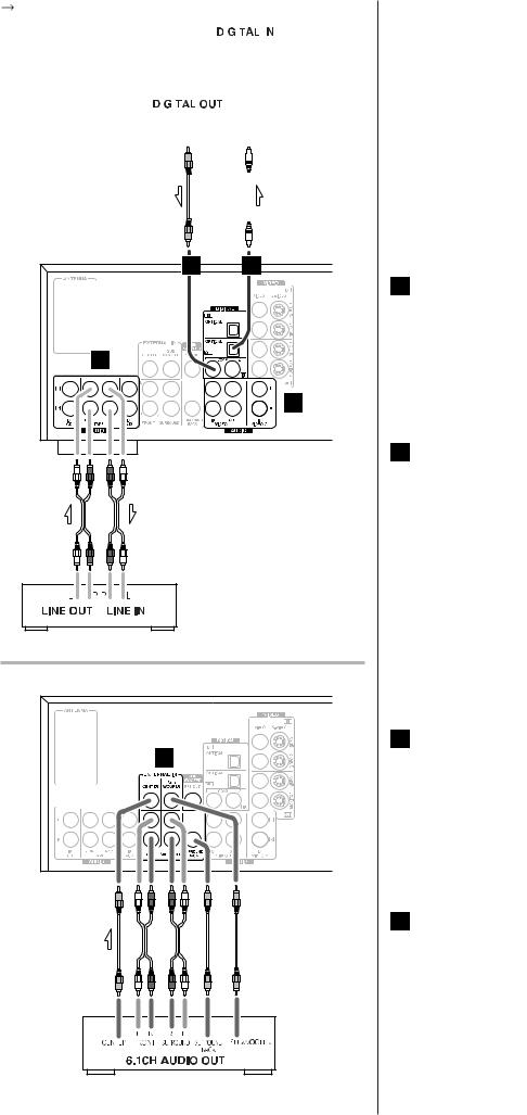
Connection to audio/video components |
|
||
|
|
A DIGITAL IN terminals |
|
|
Used for the input of digital audio signals. Connect these |
|
|
digital input terminals to the appropriate digital output |
C |
|
terminals of the digital audio source unit such as a DVD or |
|
CD player. |
|
|
|
|
|
C |
Use a good quality RCA coaxial cable or optical digital |
|
cable. |
B DIGITAL OUT terminal
The digital signals coming in through the DIGITAL IN terminals are sent out through this terminal.
Connect to the digital input terminal of a digital recording device such as a CD recorder using a commerciallyavailable optical digital cable.
When inserting the plug of the optical cable, the protective shutter of the terminal will open and you should hear it
TAPE click into position when fully inserted. Be careful that you do not force the plug, because this could result in damage to the protective shutter, the cable, or the unit itself.
D |
C AUDIO IN/OUT jacks |
|
Analog 2-channel audio signal is input or output from |
||
|
||
|
these jacks. Connect the component with commercially- |
|
|
available RCA cables. |
Make sure to connect:
white plug |
white jack (L: left channel) |
red plug |
red jack (R: right channel) |
D EXTERNAL IN jacks
If your DVD player or decoder has 6 or 7-channel analog audio outputs, connect them with good quality RCA cables.
If the component to be connected has only 6 channel outputs, do not use the SURROUND BACK jack.
DVD player or Decoder
6
F |
E |
H |
G
DVD, VCR, etc.
TV (MONITOR)
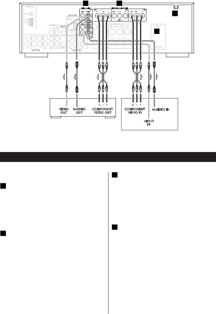
Connection 2
Connection to a TV and video components
E COMPONENT IN/OUT jacks
COMPONENT VIDEO provides the best video quality and should be used as your first choice.
If your DVD player and TV (or monitor) have COMPONENT VIDEO jacks, connect them with quality component video cables.
F S-VIDEO or VIDEO jacks
S-VIDEO connection is your second choice and is superior to the standard composite video connection.
If the component has an S-VIDEO jack, connect it with a high quality S-VIDEO cable.
If neither COMPONENT VIDEO nor S-VIDEO is available, connect the component with a high quality RCA cable designed for video applications.
The video signal from COMPONENT, S-VIDEO or VIDEO jacks cannot be mixed.
For example, the signal input into the COMPONENT IN jacks is output from the COMPONENT OUT jacks only. Be sure to connect all the components via the same kind of jacks.
G AC OUTLET (switched)
Not available for AUSTRALIA, UK model.
This outlet is active only when the unit is on.
Caution:
Make sure that the total power consumption of all equipment connected to the outlet(s) does not exceed 100 watts.
H AC Power Cord
After all other connections are complete, connect the plug to the AC wall socket.
If you are not going to use the unit for some time, disconnect the power cord from the wall socket. (Leaving the power cord unconnected for longer than 14 days will cause the tuner memory presets to be lost.)
Be sure to connect the power cord to an AC outlet which supplies the correct voltage.
Hold the power plug when plugging or unplugging the power cord.
7

Example: Connection to a DVD player
8
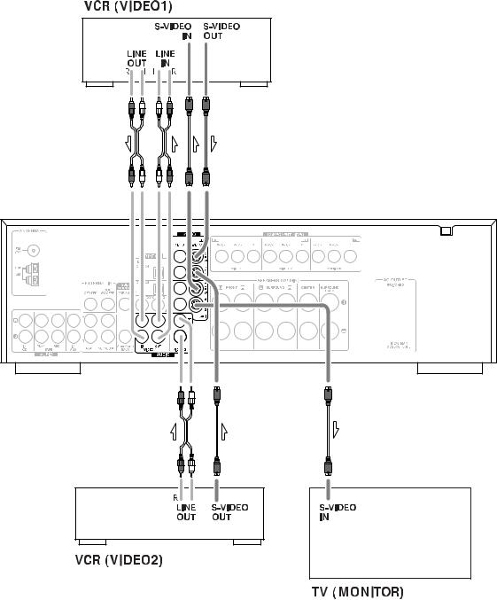
Example: Connection to Video Cassette Recorders
9
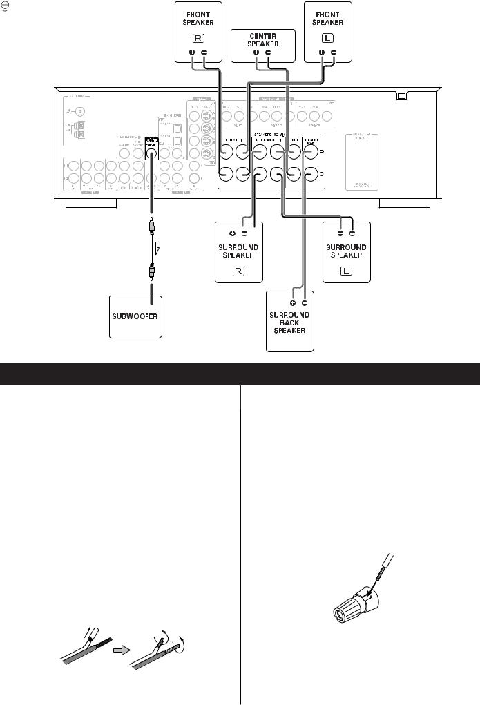
Speaker Connections
Caution:
To avoid damaging the speakers with a sudden high-level signal, be sure to switch the power off before connecting the speakers.
Check the impedance of your speakers. Connect speaker with an impedance of 6 ohms or more.
The black speaker terminals are (negative).
Generally, the |
side of the speaker cable is marked to |
|
make it distinguishable from the |
side of the cable. |
|
Connect this marked side to the |
terminal and the |
|
unmarked side to the black terminal. |
|
|
Prepare the speaker cables for connection by stripping off approximately 10 mm or less of the outer insulation. (Removing too much insulation may lead to a short circuit if the bared wired should come in contact with each other.) Twist the strands of the stripped wires tightly together :
Caution:
The metal portions of the two separate wires should not touch or an electrical short can occur. Shorted wires can create a fire hazard or induce a failure in your equipment.
How to connect:
1.Turn the terminal cap counterclockwise to loosen it. The speaker terminal caps cannot be fully removed from the base.
2.Insert the wire into the terminal fully and turn the terminal cap clockwise to securely connect it:
Make sure none of the wire insulation is under the terminal, only the bare, stripped wire.
3. Make sure it is fastened firmly by pulling the cable lightly.
10
|
|
|
|
|
|
|
|
|
|
|
|
|
|
|
|
|
|
|
|
Positioning of the Speakers |
|
|
|
|
|
|
|
|
|
|
|
|
|
|
|
|
|
|
|
|
The positioning of speakers differs according to the size |
|
|
|
|
|
|
|
|
|
|
|
|
|
|
|
|
|
|
|
|
and acoustics of the listening room. While actually listening |
|
|
|
|
|
|
|
|
|
|
|
|
|
|
|
|
|
|
|
|
to a program source, try various speaker positions to |
|
|
|
|
|
|
|
|
|
|
|
|
|
|
|
|
|
|
|
|
determine which layout provides the best surround effect. |
|
|
|
|
|
|
|
|
|
|
|
|
|
|
|
|
|
|
• |
|
Ideally, position all the speakers in a circle, with the same |
|
|
|
|
|
|
|
|
|
|
|
|
|
|
|
|
|
|
|
|
distance from your listening position. |
|
|
|
|
|
|
|
|
|
|
|
|
|
|
|
|
|
|
• |
|
Place the speakers connected to “L” to your left, and “R” to |
|
|
|
|
|
|
|
|
|
|
|
|
|
|
|
|
|
|
|
|
your right. |
|
|
|
|
|
|
|
|
|
|
|
|
|
|
|
|
|
|
|
Front speakers |
|
|
|
|
|
|
|
|
|
|
|
|
|
|
|
|
|
|
|
A |
||
|
|
|
|
|
|
|
|
|
|
|
|
|
|
|
|
|
|
|
||
|
|
|
|
|
|
B |
|
|
|
|
|
|
|
|
|
|
|
|
|
Use magnetically shielded speakers, if you are using them |
|
|
|
|
A |
|
|
|
A |
|
|
|
|
|
|
|
|
|
|
||
|
|
|
|
|
|
|
|
|
|
|
|
|||||||||
|
|
|
|
|
|
|
|
|
|
|
|
|
|
|
|
|
|
|
|
near your TV. |
|
|
|
|
|
|
|
|
|
|
|
|
|
|
|
E |
|
|
|
|
|
|
|
|
|
|
|
|
|
|
|
|
|
|
|
|
|
|
|
|
Place the front speakers in front of the listening position, to |
|
|
|
|
|
|
|
|
|
|
|
|
|
|
|
|
|
|
|
|
|
|
|
|
|
|
|
|
|
|
|
|
|
|
|
|
|
|
|
|
|
|
the left and right of a TV. |
|
|
|
|
|
|
|
|
|
|
|
|
|
|
|
|
|
|
|
|
Front speakers are required for all surround modes. |
|
|
|
|
|
|
|
|
|
|
|
|
|
|
|
|
|
|
|
|
Center speaker |
|
|
|
|
|
|
|
|
|
|
|
|
|
|
|
|
|
|
B |
||
|
|
|
|
|
|
|
|
|
|
|
|
|
|
|
|
|
|
|
||
|
|
|
|
|
|
|
|
|
|
|
|
|
|
|
|
|
|
|
|
Use a magnetically shielded speaker if you are using it near |
|
|
|
|
|
|
|
|
|
|
|
|
|
|
|
|
|
|
|
|
your TV. Place a center speaker between the front |
|
|
|
|
|
|
|
|
|
|
|
|
|
|
|
|
|
|
|
|
speakers, on or below the TV. This speaker stabilizes the |
|
|
|
|
|
|
|
|
|
|
|
|
|
|
|
|
|
|
|
|
sound image. |
|
C |
|
|
|
|
|
|
|
|
|
|
C |
|
|
|
|
|
|
||
|
|
|
|
|
|
|
|
|
|
|
|
|
|
|
|
|
|
|
|
Surround Left and Right speakers |
|
|
|
|
|
|
|
|
|
|
|
|
|
|
|
|
|
|
|
|
|
|
|
|
|
|
|
|
|
|
|
|
|
|
|
|
|
|
|
C |
|
|
|
|
|
|
|
|
|
|
|
|
|
|
|
|
|
|
|
|
|
||
|
|
|
|
|
|
|
|
|
|
|
|
|
|
|
|
|
|
|
||
|
|
|
|
|
|
|
|
|
|
|
|
|
|
|
|
|
|
|
|
Install these speakers above the level of the listener’s ears, |
|
|
|
|
|
|
|
|
|
|
|
|
|
|
|
|
|
|
|
|
directly to the left and right (or slightly behind) of your |
|
|
|
|
|
|
|
|
|
|
|
|
|
|
|
|
|
|
|
|
listening position. |
|
|
|
|
|
|
|
|
|
|
|
|
|
|
|
|
|
|
|
|
|
|
|
|
|
|
|
D |
|
|
|
|
|
|
|
|
|
|
|
|
|
|
|
|
|
|
|
|
|
|
|
|
|
|
|
|
|
|
|
|
|
|
Surround Back speaker |
|
|
|
|
|
|
|
|
|
|
|
|
|
|
|
|
|
|
D |
||
|
|
|
|
|
|
|
|
|
|
|
|
|
|
|
|
|
|
|
||
|
|
|
|
|
|
|
|
|
|
|
|
|
|
|
|
|
|
|
|
Place the surround back speaker at the back of the listening |
|
|
|
|
|
|
|
|
|
|
|
|
|
|
|
|
|
|
|
|
position facing the front at a slightly higher position than the |
|
|
|
|
|
|
|
|
|
|
|
|
|
|
|
|
|
|
|
|
surround left and right speakers. Point slightly downward. |
|
|
|
|
|
|
|
|
|
|
|
|
|
|
|
|
|
|
|
|
Subwoofer |
|
|
|
|
|
|
|
|
|
|
|
|
|
|
|
|
|
|
E |
||
|
|
|
|
|
|
|
|
|
|
|
|
|
|
|
|
|
|
|
||
|
|
|
|
|
|
|
|
|
|
|
|
|
|
|
|
|
|
|
|
Reproduces powerful and deep bass sounds. |
|
|
|
|
|
|
|
|
|
|
|
|
|
|
|
|
|
|
|
|
Use a sub-woofer with built-in amplifier referred to as a |
|
|
|
|
|
|
|
|
|
|
|
|
|
|
|
|
|
|
|
|
“powered sub-woofer”. Subwoofers are most effective when |
|
|
|
|
|
|
|
|
|
|
|
|
|
|
|
|
|
|
|
|
placed on or near the floor and in a corner of the room. |
|
|
|
|
|
|
|
|
|
|
|
|
|
|
|
|
|
|
|
|
Refer to the instructions that came with your sub-woofer for |
|
|
|
|
|
|
|
|
|
|
|
|
|
|
|
|
|
|
|
|
placement suggestions. |
|
|
|
|
|
|
|
|
|
|
|
|
|
|
|
|
|
|
|
|
|
11

Names of Each Control 1
Front Panel
Remote Control Unit
12
 Loading...