


Model:PLED2435A-I

CONTENTS
English
SAFETY
1
PRECAUTION
IMPORTANT
SAFETY
2
INSTRUCTION
ACCESSORIES
3
GETTING
4
STARTED
CONTROL
5
REFERENCE
GUIDE
CONNECTIONS
6
Remote Control
Front View
Back View
Front View
Antenna Connection
AV Connection
YPbPr Connection
HDMI Connection
VGA Connection
Headphone Connection
Power Cord Connection
Coax(SPDIF) Connection
1
2
3
3
4
5
5
6
7
7
8
8
9
9
9
10
WALL MOUNT
7
INSTALLATION
INITIAL SETUP
8
TV SETUP
9
Putting The Unit On A Proper Place
Source Selection
Turning The Unit On For The First Time
TV(CHANNEL) Menu
Picture Menu
Audio Menu
Time Menu
Setup Menu
LOCK(Parental) Menu
11
12
12
12
13
14
15
16
17
18

CONTENTS
10
11
12
DISPLAY
MODE
SPECIFICATION
TROUBLESHOOTING
GUIDE
PC Formats
Video Formats
TV Symptom
19
20
21
22
SAFETY CLASS :This is an IEC safety class I product
and it must be grounded for safety.
SAFETY PRECAUTION
CAUTION MARKING WAS LOCATED AT THE REAR
*
OF THE A PPA RATUS .
WARNING: TO REDUCE THE RISK OF ELECTRIC
SHOCK,DO NOT REMOVE COVER(OR BACK)
NO USER SERVICEABLE PARTS INSIDE.
REFER SERVICING TO QUALIFIED SERVICE
PERSONNEL.
The lightning flash with arrowhead symbol,
within an equilateral triangle,is intended to
alert the user to the presence of uninsulated
“dangerous voltage”within the product's enclosure
that may beof sufficient magnitude to constitute a
risk of electric shock to persons.
The exclamation point within an equilateral
Triangle is intended to alert the user to
The presence of important operating and
maintenance (servicing) instructions in the literature
accompanying the appliance.
CAUTION
•
DANG ER OF EXPLOS ION IF BA TTERY I S
INCO RRECTLY RE PLACE D. REPL ACE O NLY
WITH T HE SAME OR EQU IVALE NT TYPE .
•
USE OF C ONTROLS OR A DJUST MENTS O R
PERFORMANCE OF PROCEDURES OTHER
THAN THOSE SPECIFIED MAY RESULT IN
HAZARDOUS RADIATION EXPOSURE.
WARNING:
TO RED UCE THE RISK O F FIRE OR E LECTR IC
•
SHOC K, DO NOT EXPO SE THIS A PPLIA NCE TO
RAIN O R MOISTURE .
TO REV ENT FIRE OR SH OCK HAZ ARD, DO N OT
•
EXPO SE THIS UNIT T O RAIN OR M OISTU RE. DO
NOT PL ACE OBJECT S FILLE D WITH LI QUIDS ON
OR NEA R THIS UNIT.
•
SHOU LD ANY TROUB LE OCCU R, DISC ONN ECT
THE AC P OWER CORD AN D REFER S ERVIC ING
TO A QUA LIFIED TEC HNICI AN.
PLACEMENT INFORMATION
•
Do not u se this unit i n place s that ar e ext remel y
hot, c old, dusty o r humid .
•
Do not r estrict th e airfl ow of thi s uni t by plac ing it
some whe re with p oor air flow, by cov ering i t with
a cloth, by placing it on bedding or carpeting.
SAFETY INFORMATION
•
When connecting or disconnecting the AC power
cord , grip the plu g and not t he cord itse lf. Pul ling
the co rd may damag e it and cr eate a hazar d.
•
When y ou are not goi ng to use t he unit for a lo ng
period of time, disconnect the AC power cord.
RATING PL ATE LOCATION
The rating plate is located on the rear of the unit.
FCC STATEMENTS
NOTE : This unit ha s been te sted an d fou nd to com ply
with t he limits fo r a Class B d igita l dev ice, pu rsuan t
to Par t 15 of the FCC Ru les. Th ese lim its a re desi gned
to provide reasonable protection against harmful
inte rference i n a resid ential ins talla tion.
This unit generates, uses and can radiate radio
frequency energy and, if not installed and used in
accordance with the instructions, may cause harmful
interference to radio communication. However, there
is no guarantee that interference will not occur in a
part icular ins talla tion. If thi s unit do es caus e harmful
interference to radio or television reception, which
can be d etermine d by turn ing the unit o ff and on , the
user i s encourag ed to try t o corre ct th e inter feren ce
by one o r more of the fo llowi ng measure s:
- Reorient or relocate the receiving antenna.
- Incr ease the sep arati on between t he unit a nd
receiver.
-Connect the unit into an outlet on a circuit diff erent
from that to which the receiver is connected.
- Cons ult the deal er or an ex perience d radio /TV
technician for help.
WARNING:
Changes or modifications to this
not expressl y app roved by the part y res pon sible
unit
for compliance could void the user authority
to operate the u nit .
“HDMI, the HDMI logo and High-Definition Multimedia
Interface are trademarks or registered trademarks of
HDMI Licensing LLC.”
1

IMPORTANT SAFETY INSTRUCTIONS
1)Read these instructions.
2)Keep these instructions.
3)Heed all warnings.
4)Follow all instructions.
5)Do not use this apparatus near water.
6)Clean only with a dry clot h.
7)Do not block any ventilation openings.
Inst all in accor dance w ith the
manufacturer's instructions.
8)Do no t ins tall ne ar any he at sources s uch
as radiators, heat registers, stoves, or
other apparatus (Including amplifiers) that
produce heat.
9)Do not defect the safety purpose of the
polarized or grounding-type plug.
A polarized plug has two blades with one
wide r than the oth er.
A grou ndi ngtyp e plug has two blades
and a third grounding prong.
The wi de bl ade or th e third p rong is
prov ide d for you r safet y.
If the p rovided pl ug does n ot fit into yo ur
wall o utl et, con sult an e lectrici an for
replacement of the obsolete outlet.
10)Protect the power cord from being walked on
or pin ched parti cular ly at plugs, c onven ience
rece ptacles, a nd the po int where th ey exit
from t he apparat us.
11)On ly us e attac hment s / accessor ies spe cified
by the m anufacturer.
12)Us e onl y with th e cart, s tand,
trip od, bracke t, or tab le
spec ified by the manufacturer,
or sol d with the app aratu s.
When a c art is used, u se caut ion when
movi ng the cart / ap parat us combina tion to
avoi d injury from tip-over.
13)Unplug this apparatus during lightning
Stor ms or when unu sed for l ong period s of
time .
14)Refe r all s ervic ing to qu alified se rvice
pers onnel. Ser vicin g is required when the
appa ratushas b een dam aged in any wa y,
such a s the power co rd or plu g is damaged ,
liqu id has been sp illed or objects have fallen
into t he apparat us, the a pparatus h as been
expo sed to rain or m oistu re, does not o perat e
norm ally, or has b een dro pped.
15)To pre ven t elect ric sho ck, ensure t he grou nding
pin on t he AC cord pow er plug i s securely
conn ected.
2
ACCESSORIES
Please check and identify the supplied accessories.
Remote control ..................................................................................................................
Remote control
x 1
Battery(AAA)
Warranty Card
Instruction Manual
Base stand and 3 base stand screws
Screw driver
............................................................................................................ .........
................................................................................................................
...........................................................................................................
......................................................................................
.................................................................................................................
GETTING STARTED
USING THE REMOTE CONTROL
·Point the remote control at the remote sensor located on the unit.
·When there is a strong ambient light source, the performance of the infrared remote sensor
·may be degraded, causing unreliable operation.
·The recommended effective distance for remote operation is about 16 feet (5 meters).
x 2
x 1
x 1
x 1
x 1
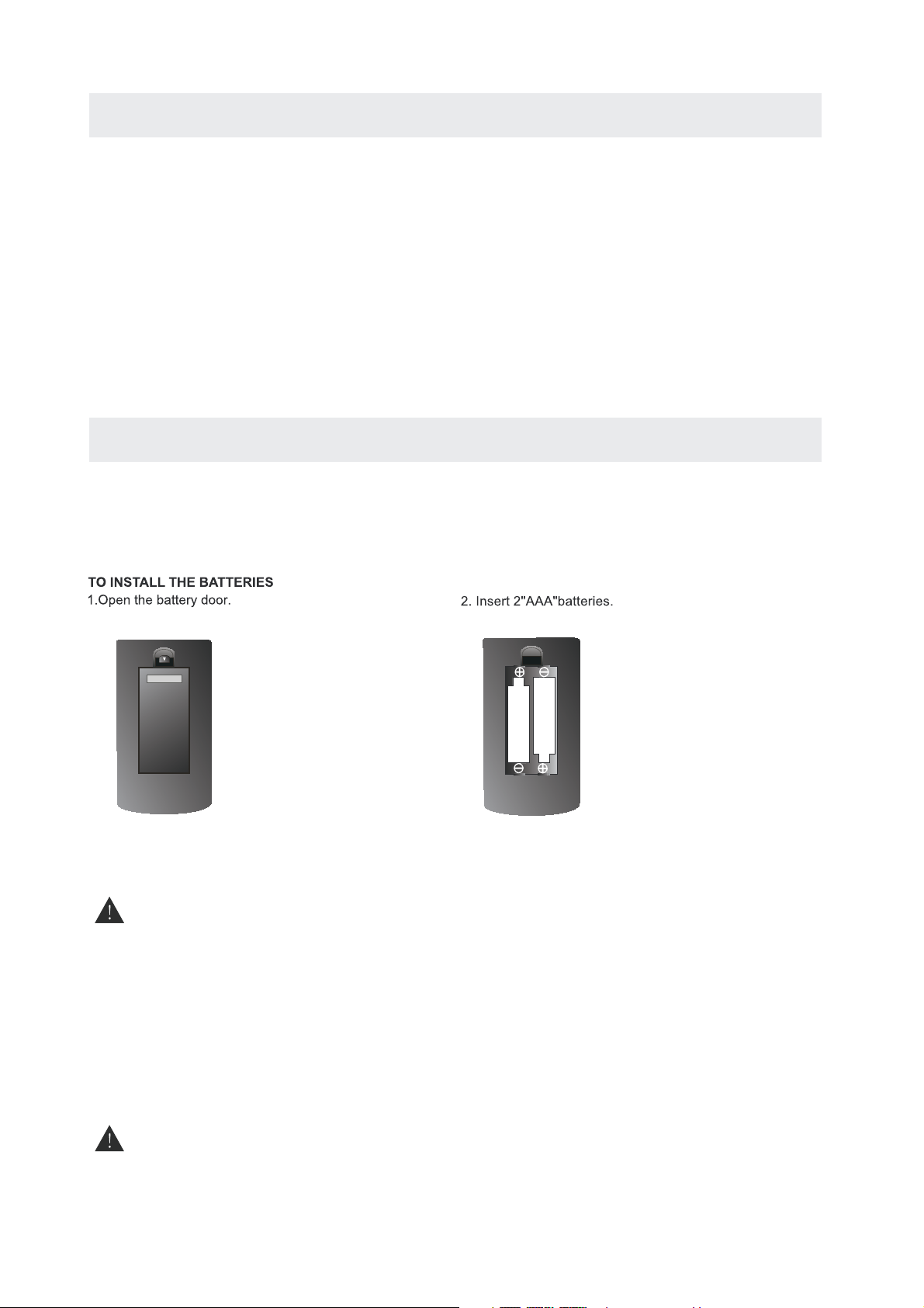
BATTERY REPLACEMENT
When the batteries become weak, the operating distance of the remote control is greatly
reduced and you will need to replace the batteries.
CAUTION : Danger of explosion if battery is incorrectly replaced.
NOTES
·If the remote control is not going to be used for a long time, remove the batteries to avoid
damage caused by battery leakage corrosion.
·Do not mix old and new batteries. Do not mix ALKALINE, standard (CARBON-ZINC) or
rechargeable (NICKEL-CADMIUM) batteries.
·Always remove batteries as soon as they become weak.
·Weak batteries can leak and severely damage the remote control.
WARNING :
Do not dispose batteries in a fire. Batteries may explode or leak.
Batt er
ies shall not be exposed to excessive heat such as sunshine, fire or the like.
3
CONTROL REFERENCE GUIDE
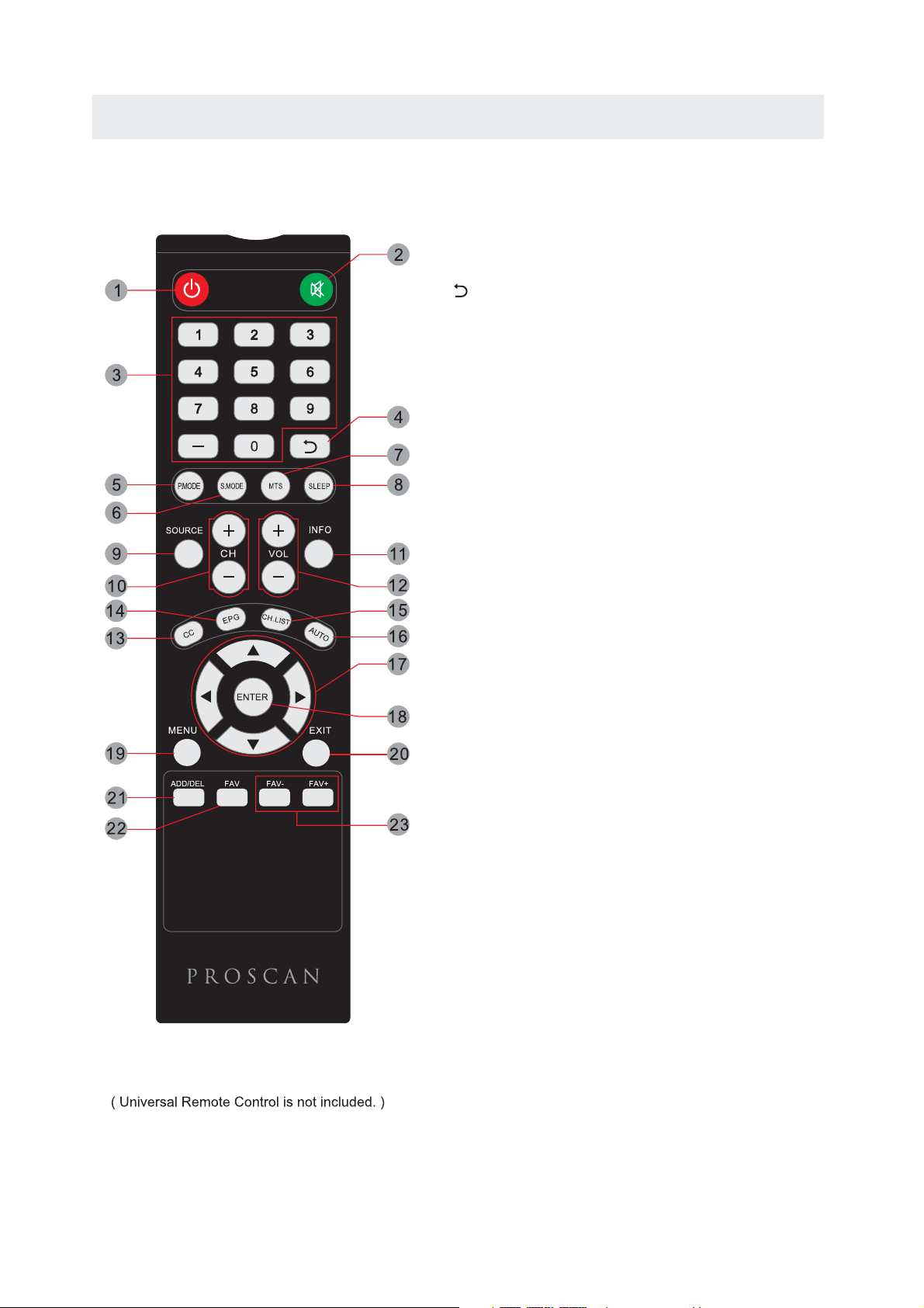
REMOTE CONTROL
1.STANDBY
To switch on the TV or make the TV into
standby mode.
2.MUTE
Press this button to mute or restore sound.
3.0-9
Allows you to change the channel of the TV.
4.
Switches back and forth between the current and
previous channels.
5.P.MODE
Press this button to select a picture mode for different
picture qualities.
6.S.MODE
Press this button to select sound setting for different
sound effects.
7.MTS
To change among STEREO, MONO and SAP. If there is no
second language available for the signal received, LED
Display audio will output to mono.
8.SLEEP
To select the amount of time before your TV turns
Off automatically.
9.SOURCE
Press this button to select an input source.
10.CH+/CHSkips to the next/previous channel on TV mode.
11.INFO
Show the information of the program you are watching.
12.VOL+/VOLIncreases/Decreases the Volume control.
13.CC
Press the button to enter into the CC mode.
14.EPG
Press this button to select the electronic programme
guide in DTV mode.
15.CH.LIST
Press this button to display the channel list.
16.AUTO
Press this button to autoadjust the screen in PC mode.
17.UP/DOWN/LEFT/RIGHT
Moves the cursor upward/downward/to the left/to the right
when making a selection.
18.ENTER
Press to confirm selections on a menu screen.
19.
MENU
Displays the OSD Menu of the TV.
Universal Remote Code: 1218
20.
Exit
Press this button to exit the on screen display.
21.ADD/DEL
Press to increase/decrease your favourtite program.
FAV
22.
Press this button to show the favourite list.
23. FAV+/FAVPress this button to go through the FAV channel list.
4
CONTROL REFERENCE GUIDE
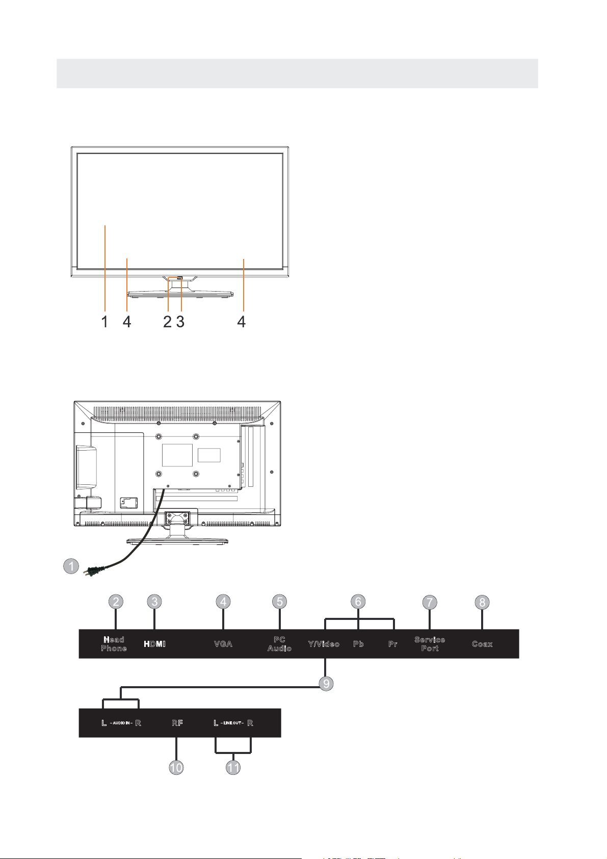
FRONT VIEW
1.Color Screen
2.Remote Sensor
Do not block this sensor or the
remote control will not work.
3.Standby Indicator
Indicates whether the unit is ON
or in STANDBY (OFF) mode.
Light in red: The unit is in STANDBY.
Light in
blue:The unit is turned ON.
4. Speakers
BACK VIEW
Head
Phon e
HDMI VGA
PC
Audi o
1.Power Cord
2.Headphone Jack
3.HDMI IN Jack
4.VGA IN Jacks
5.PC AUDIO IN Jack
6.COMPONENT IN Jack
7.Service Port
8.Coax OUT Jack
9.AV IN Jack
10.TV ANTENNA Terminal
11.AUDIO OUT Jack
Y/Video
Pb
Pr
Serv ic e
Port
Coax
HDMI3
AUDI O IN LINE O UT
L
RF
RFR
L
-AUDIO OUT-
L
R
R
5
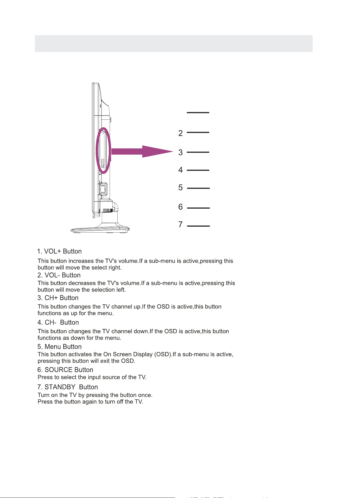
SIDE VIEW
CONTROL REFERENCE GUIDE
1
VOL+
VOL-
CH+
CH-
MENU
SOURCE
STANDBY
6
CONNECTIONS
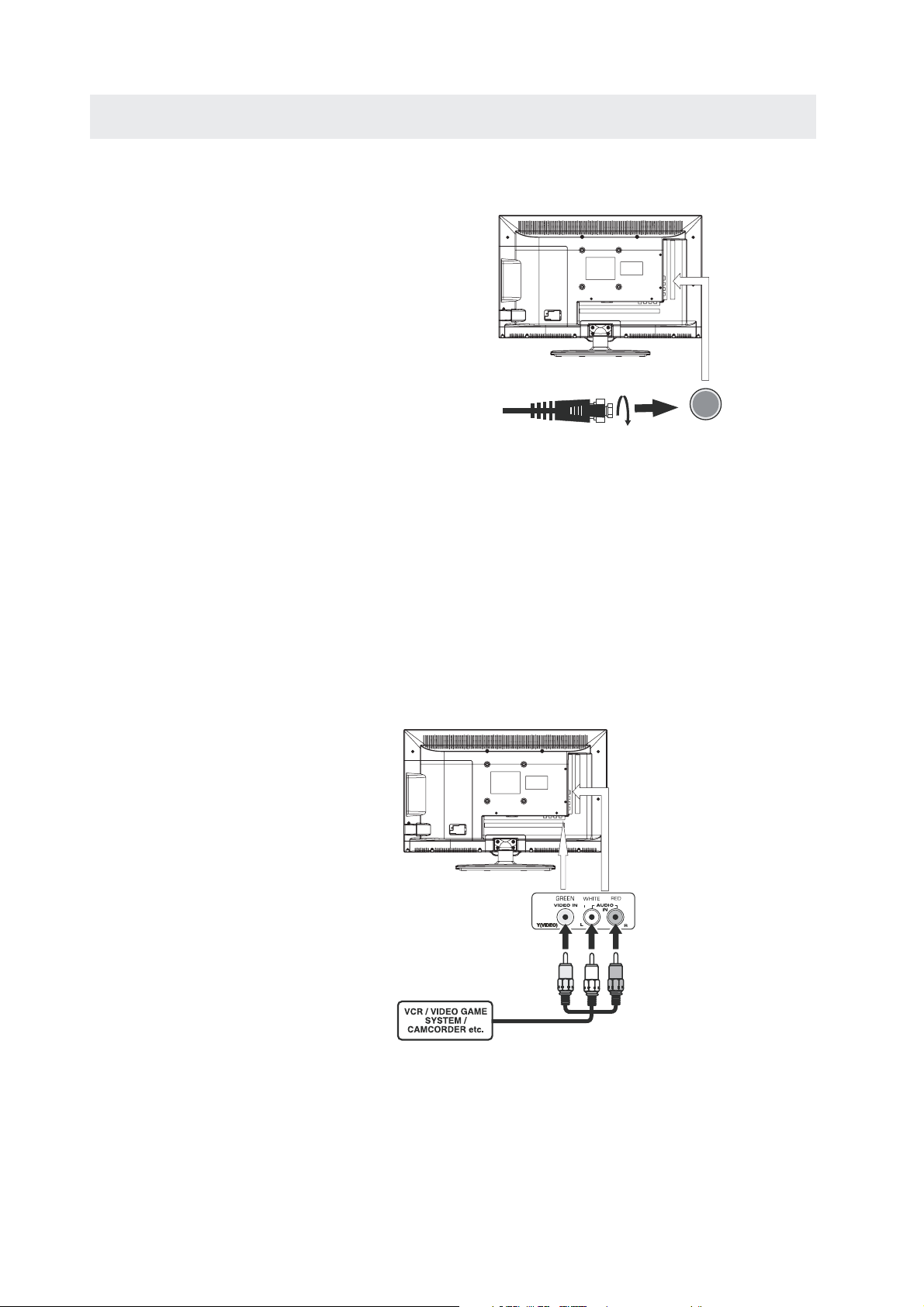
CONNECTING A TV ANTENNA / CABLE / SATELLITE
To view television channels correctly,a signal must
be received from one of the following sources:
- An indoor or outdoor aerial antenna
- A cable system
- A satellite system
NOTE
For receiving over-the-air TV broadcasts, we
recommend that you use an external fixed antenna.
Should you require the use of a temporary antenna,
please ensure that you purchase an antenna with
sufficient ability to receive in
Only when you are in close proximity to a transmitter
will a temporary antenna reproduce a signal as
strongly as a fixed antenna.
CONNECTINGAN A/V DEVICE
To connect to other equipment such as a VCR, camcorder,satellite system or cable, etc.
weak signal areas.
Satellite, cable or TV antenna
cable to TV ANTENNA
terminal (cable not included)
CONNECTING DEVICES WITHA COMPOSITE (GREEN RCA-TYPE)
VIDEO OUTPUT
To connect A/V devices such as a VCR, video game s
ystem or camcorder.
Connecting to a VCR / Video Game System / Camcorder
Connect the AUDIO / VIDEO cable (not included) as shown.
Make sure you connect the cable from the other equipment ( and ) to this unit
AUDIO VIDEO OUT
(AV in)
NOTE
1.Please refer to the user manual
for the other equipment for
more information.
2. Composite video input
(shared with component)
To AUDIO / VIDEO
OUT jacks
To AUDIO / VIDEO
IN jacks
7
CONNECTIONS
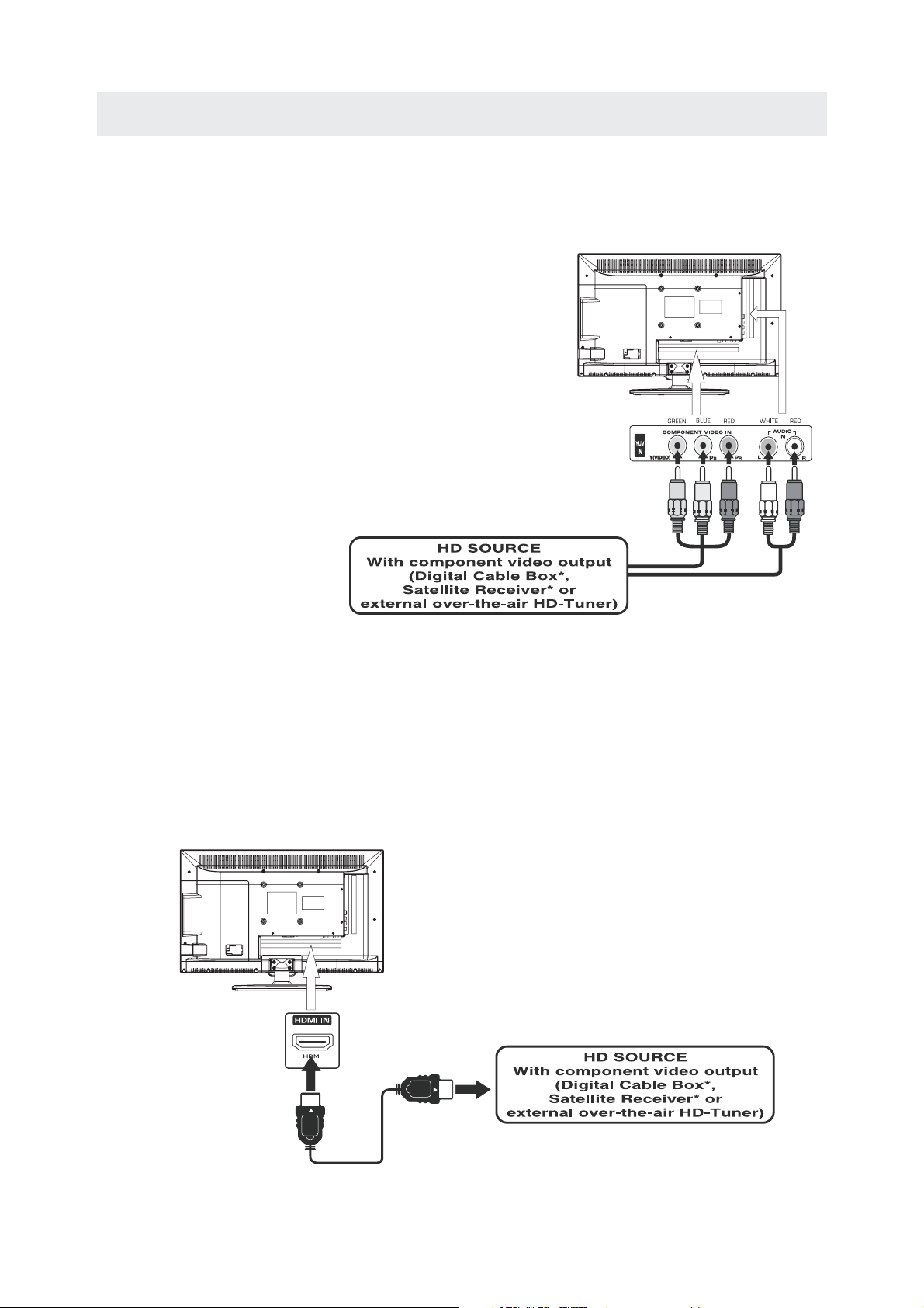
CONNECTINGA HIGH-DEFINITION (HD) SOURCE USING CONNECTION
High-Definition (HD) Devices with component video output must be connected to the Y input.
Connect the component video cable and audio cable (not included) as shown.
Make sure you connect the component video cable and audio cable from the other equipment
˄COMPONENT OUT andAUDIO OUT˅to the unit COMPONENT IN.
COMPONENT
PbPr
NOTE
When connecting a DVD player to the television,
the picture resolution is solely dependent upon
the resolution su
pported by the DVD player attached.
DVD player resolutions vary from 480i to 1080i.
and this television can support DVD players up to
a maximum resolution of 1080i.
*May require asubscription
COMPONENT IN
for receiving HD channels,
check with your cable/satellite
service provider for details.
To COMPONENT
VIDEO IN jacks
To COMPONENT
VIDEO OUT jacks
To COMPONENT AUDIO
OUT jacks
To COMPONENT
AUDIO IN jacks
CONNECTINGA HIGH-DEFINITION (HD) SOURCE USING HDMI CONNECTION
HDMI (High Definition Multimedia Interface) supports both video and audio on a single digital connection
for use with DVD players, DTV, set-top boxes and other digital AV devices. HDMI was developed to provide
the technologies of High Bandwidth Digital Content Protection (HDCP) as well as Digital Visual Interface
(DVI) in one specification. HDCP is used to protect digital content transmitted and received by
DVI-compliant or HDMIcompliant displays.
HDMI has the capability to support standard, enhanced or high-definitio
multi-channel surround-sound audio. HDMI features include uncompressed digital video, a bandwidth of
up to 2.2 gigabytes per second (with HDTV signals), one connector (instead of several cables and
connectors), and communication between the AV source and AV devices such as DTVs.
Connect the HDMI cable (not included) as
shown:
Make sure you connect the cable from the
source equipment ( ) to this unit
().
HDMI IN
HDMI CABLE
(NOT INCLUDED)
n video plus standard to
HDMI OUT
To HDMI
IN jack
To HDMI
jackOUT
8
CONNECTIONS
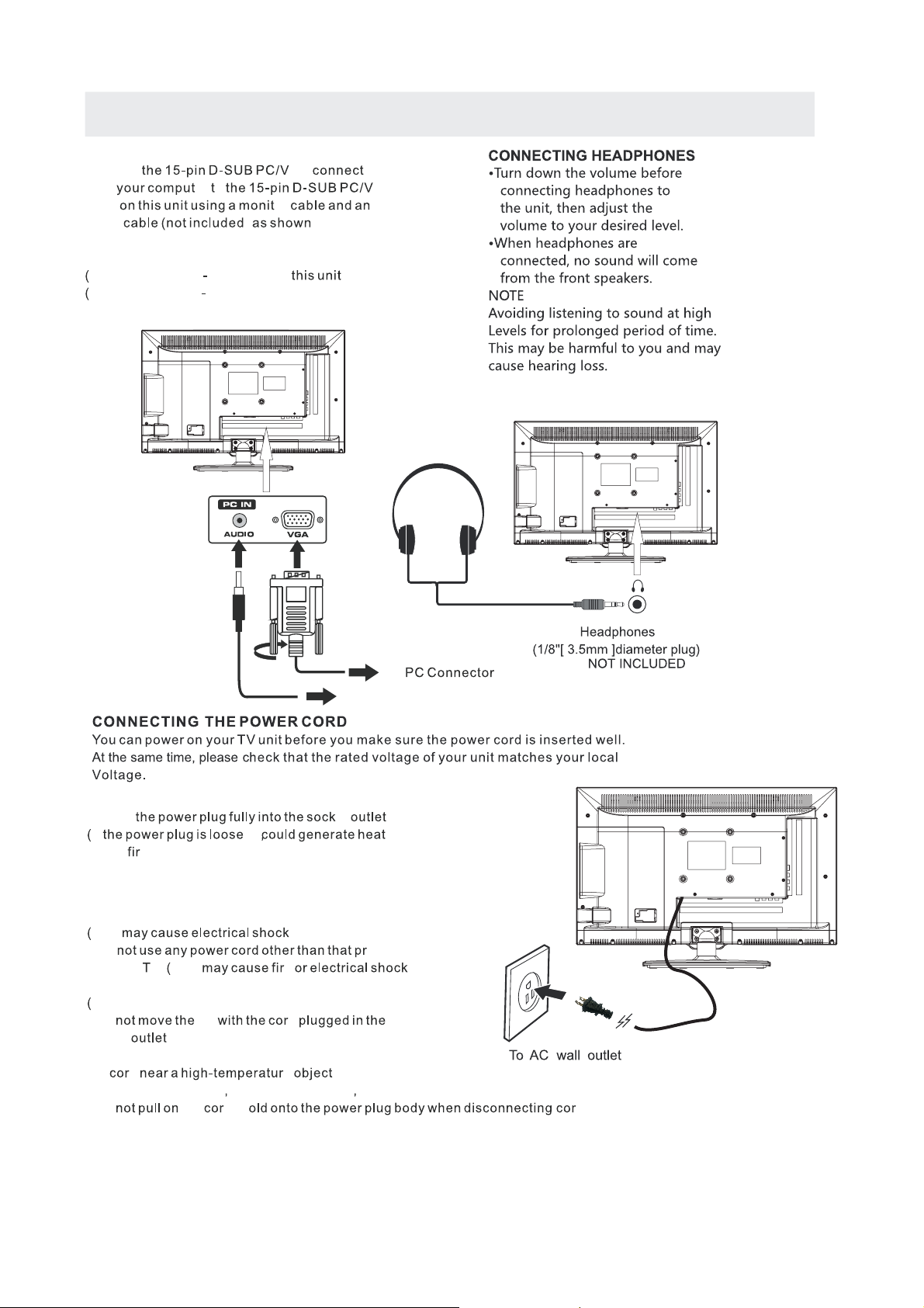
CONNECTING A
Connect
from
input
audio ) .
Make sure you connect the cable from the computer
AUDIO
and ) to
VGA
and ).
VGA AUDIO
PC
GA or
er o GA
or
PC OUT
PC IN
TO
TO AUDIO OUT jacks
NOTE
t Insert
If it and
.)
cause
t
t
connected to prevent electrical shock.
t
This
t
with this
t
A damaged cord may cause fire or electrical shock
t Do
socket .
t Do not place a heavy object on the cord or place
the
t Do not twist the cord
t Do
t Do not use a damaged power plug or socket outlet.
e
Ensure that the power plug is easily accessible.
Ensure the earth pin on the power plug is securely
Do not touch the power plug with a wet hand
Do ovided
.
VThis e
Do not damage the power cord
TV d
d e .
bend it excessively or stretch it.
the d. H d.
.
et
.)
.
.
.)
.)
9
CONNECTIONS
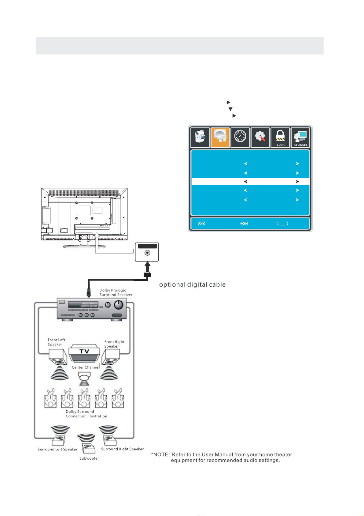
Connection to a Home Theater Audio System
For BEST audio performance
Connecting to a Home Theater System
Dolby Digital can deliver optimal 2 channel
stereo or surround sound with five discrete
full range channels plus a sixth channel for
a subwoofer.
Enjoy optimal sound reproduction from your
system with a Dolby Digital amplifier that
incorporates a digital coaxial input. Connect
an optional digital cable directly to the
television’s Coax audio output to listen
through all inputs except VGA.
(The VGA does not support digital audio˅
SPDIF OUT
Coax
How To Se
tup Digital Output
Press the MENU button on the remote control
Press the right arrow button to select sound
Press the down arrow button to highlight
SPDIF type right Raw or PCM
12
6
Picture
Equalizer Settings
MTS
Audio Language
Digital Audio Output
Surround Sound
AVL
Sound
Move Select Exit
Tim
Setup
e
Stereo
English
PCM
Off
Off
MENU
10
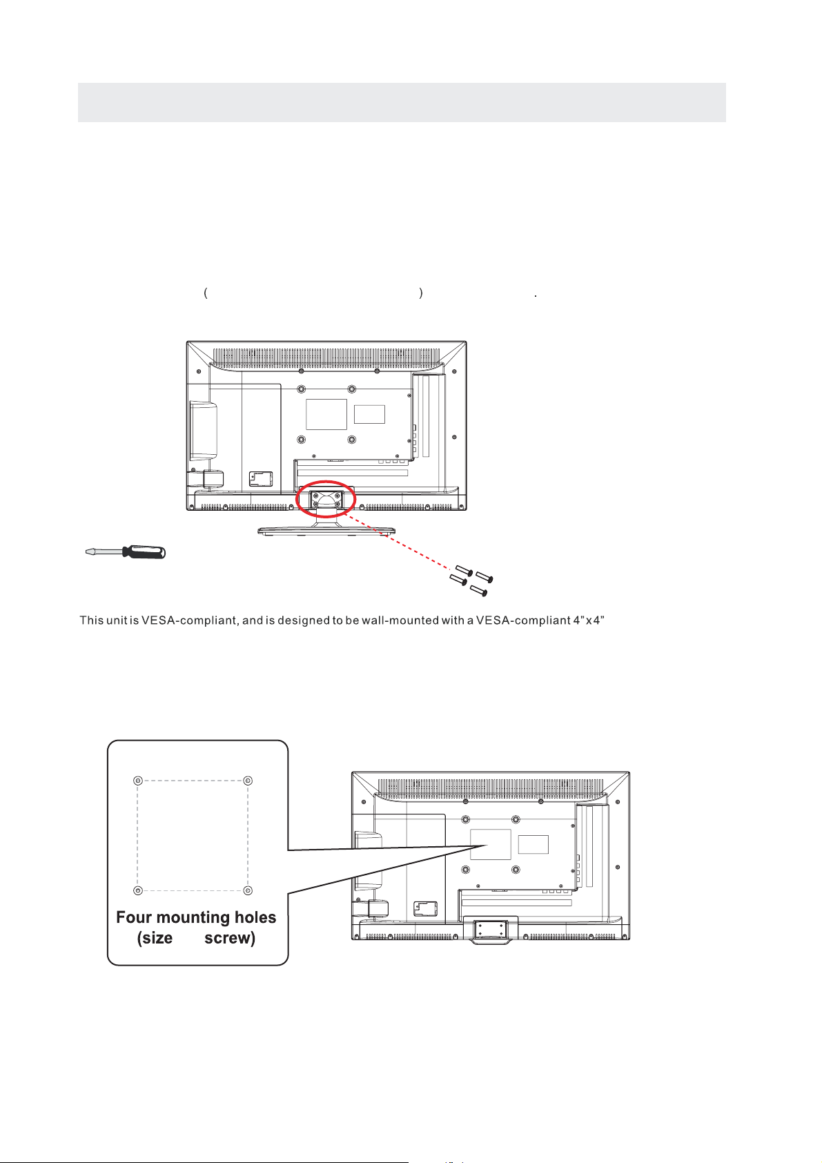
WALL MOUNT INSTALLATION
INSTALLING REMOVING THE BASE STAND
WARNING/: The
Be sure that no hard or sharp object or anything that could scratch or damage the LED display comes into
contact with it Do NOT exert pressure on the front of the unit at any time because the screen could crack
1 Disconnect all cables or cords connected to the unit
..
. .
2 Lay the unit
cushioned material such as a pillow or thick piece of foam beneath the screen
.,
3 To remove the base stand loosen screws off the holes then pull downwards to release
the base stand
LED Display is very fragile and must be protected a t all t imes w hen r emoving t he b ase
.
Stand
. .
down on a flat surface with the back side facing up Please make sure to place a soft
.
,
MOUNTING ON THE WALL
(100mm x 100mm) mounting kit designed for flat-panel TVs (not supplied). Mount this unit according to
the instructions included in the mounting kit.
Length of screw should not exceed 6 mm.
NOTE
Remove the base stand before mounting the unit on the wall.
4”
4”
M4
11
INITIAL SETUP
PUTTING THE UNIT ON A PROPER PLACE
When you turn on your television set for
the first time, be sure to place it on a solid
stable surface.
To avoid danger, do not expose the TV
to water, or a heat source
(e.g. lamp, candle, radiator).
Do not obstruct the ventilation grid
at the rear and be sure to leave sufficient
gaps around the unit.
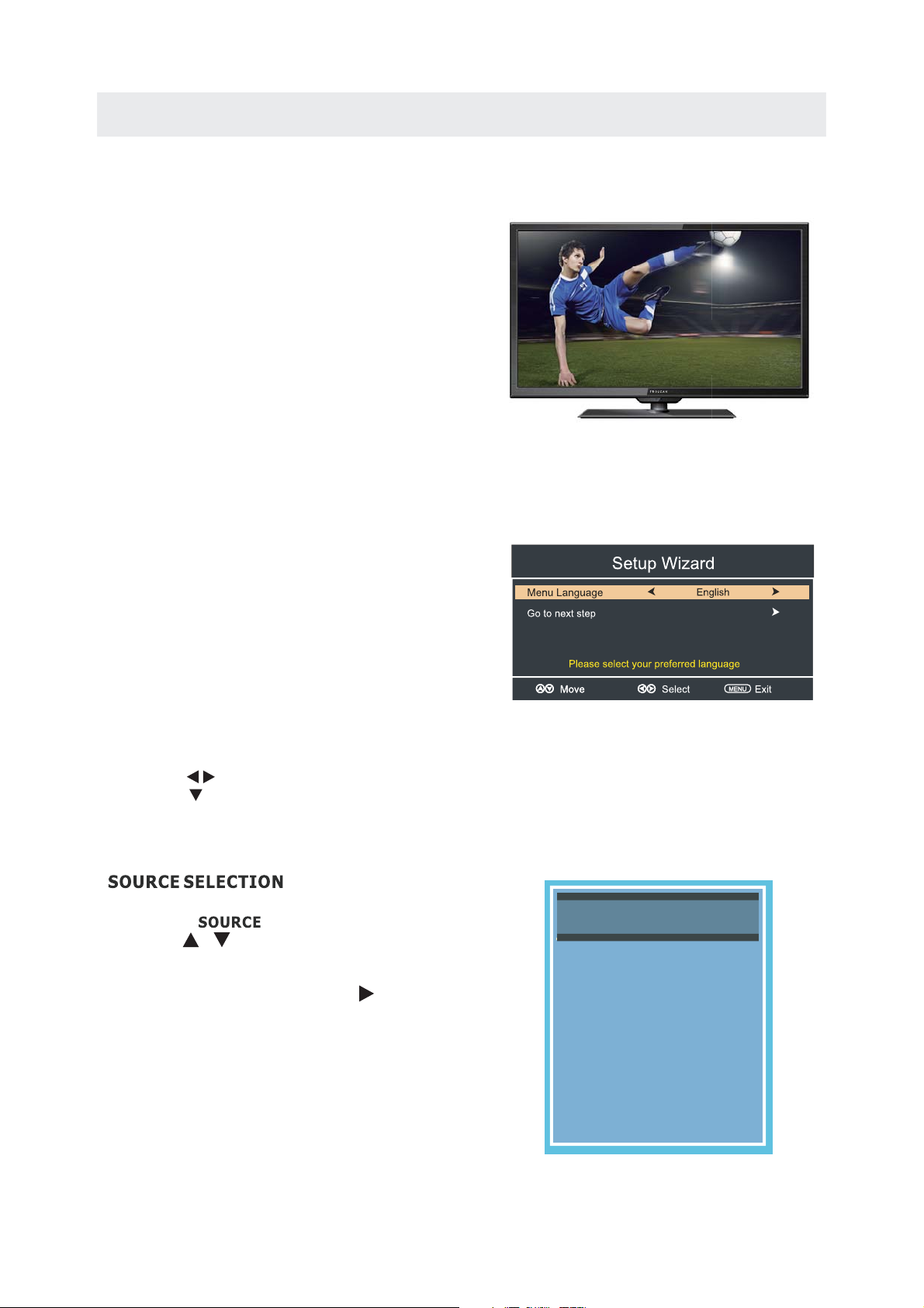
TURNING THE UNIT ON FOR THE FIRST TIME
After you have initially connected your TV
antenna or cable,
turn the television ON.
A screen will display asking you to run a
Channel Auto Scan
available local digital channels.
It is here where you will select antenna options
and run .
Channels will be stored in the TV tuner.
Press the button on the remote control.
Using the buttons, scroll to highlight chaneel mode.
Press the button to highlight AIR/CABLE.
1. Press the button on the remote control.
2.
(TV,YPbPr/AV, HDMI, PC)
and select any of them using the button or
the button.
(The screen will change to your desired s ).
Note:
Before watching please make sure all necessary
cables and devices are connected.
Channel Auto Scan
MENU
Use or button to select the optionsthe
ENTER
to search and receive
ource
Source Select
TV
YPbPr/AV
HDMI
PC
12
 Loading...