

PLDED5068A-S
50
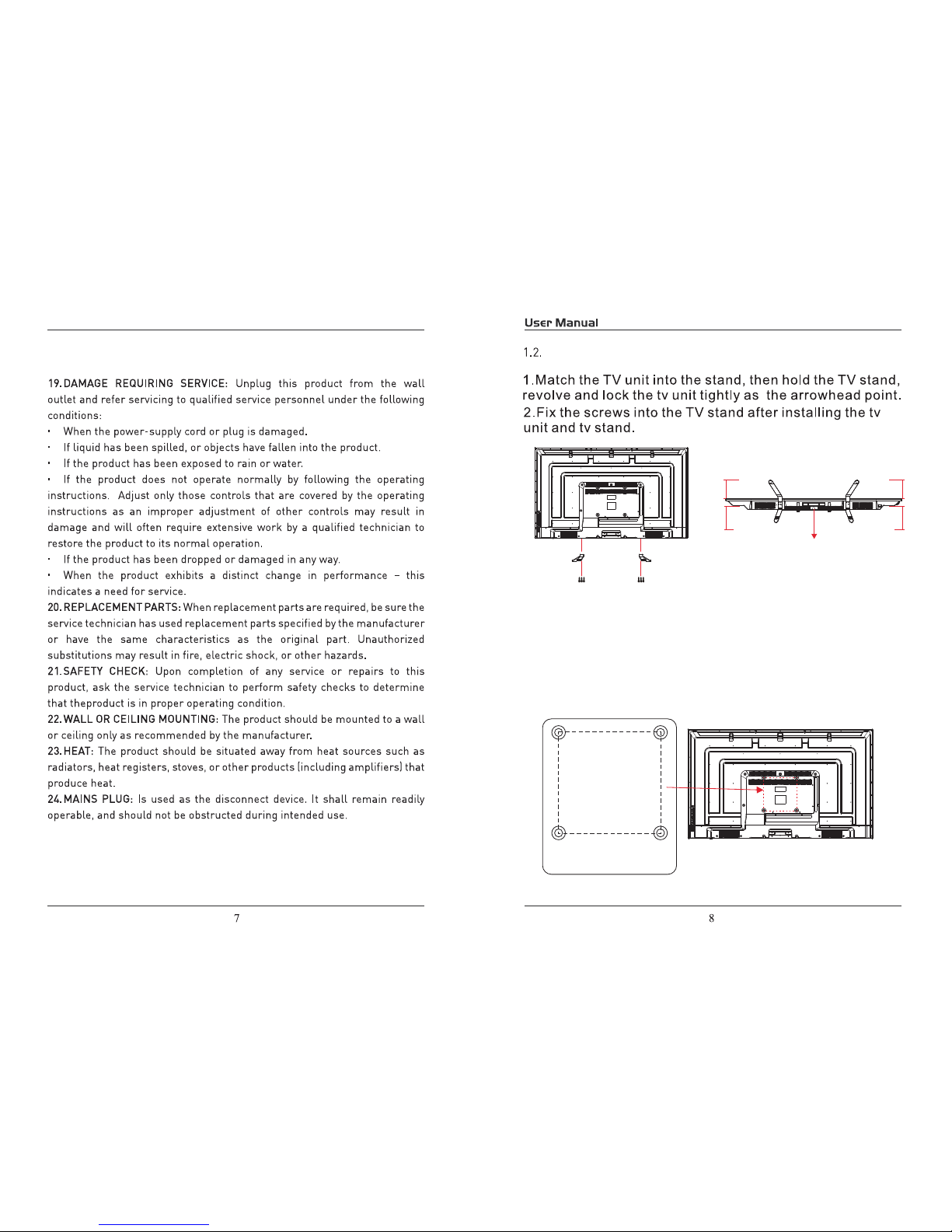
TV Base Stand assemble
17
17
17
18
19
18
30
31
32
3.2. Audio/Video Source Selection
3.1. Initial Installation
3.3. DTV Mode Operations
SETTINGS
PC Mode
Initial Setup
4.1.Customizing the PICTURE Settings
4.2.Customizing the SOUND Settings
4.3.Customizing theTIME Settings
4.4.Customizing the SETUP Settings
4.5.Customizing the LOCK Settings
4.6.Customizing the CHANNEL Settings
20
21
24
27
TV Base Stand assemble
3.Mounting on the wall
This unit is VESA-complian,and is designed to be wall-mounted
with a VESA-compliant 7.87"x7.87"(200mmx200mm)mounting kit
designde for flat-panel TVs(not supplied).Mount this unit according
to the instructions included in the monting kit. Length of screw should
not exceed 11mm
NOTE
Remove the base stand before mounting the unit on the wall.
Four mounting holes
(size M6 screw)
7.87”
7.87”
)3(swercS
4*25PWM
)3(swercS
4*25PWM
Panel side
Long Long
Short
Short
R

AUDIO OUT: Output
Audio L / R (left / right)
1. USB (For Service)
HDMI
L RAUDIO
VIDEO/
Y
Pb
Pr
COAXIAL
Headphone
HDM2 HDM3
VGA
PC AUDIO
RF
5V 0.5A
USB
AUDIO OUT
 Loading...