


Model: LDED5066A-BP
E P 4 0 0 8 5 5 4

CONTENTS
1
2
2
2
3
6
6
7
7
8
8
3
4
4
10
11
11
SAFETY
PRECAUTION
ACCESSORIES
5
CONTROL
REFERENCE
GUIDE
WALL MOUNT
INSTALLATION
INITIAL SETUP
TV SETUP
CONNECTIONS
Remote Control
Front View
Back View
Antenna Connection
AV Connection
Y Pb Pr Connection
HDMI Connection
VGA Connection
Headphone Connection
Power Cord Connection
Coax(SPDIF) Connection
Putting The Unit On A Proper Place
Turning The Unit On For The First Time
Source selection
Picture Menu
Audio Menu
Time Menu
Setup Menu
LOCK(Parental) Menu
TV(CHANNEL) Menu
Zoom Function
1
English
9
6
8
13
15
17
18
21
24
25
11
GETTING
STARTED
8
7
4

CONTENTS
26
28
29
DISPLAY
MODE
SPECIFICATION
TROUBLESHOOTING
GUIDE
PC Formats
Video Formats
TV Symptom
SAFETY CLASS : This is an IEC safety class ǁ product.
27
11
10
9
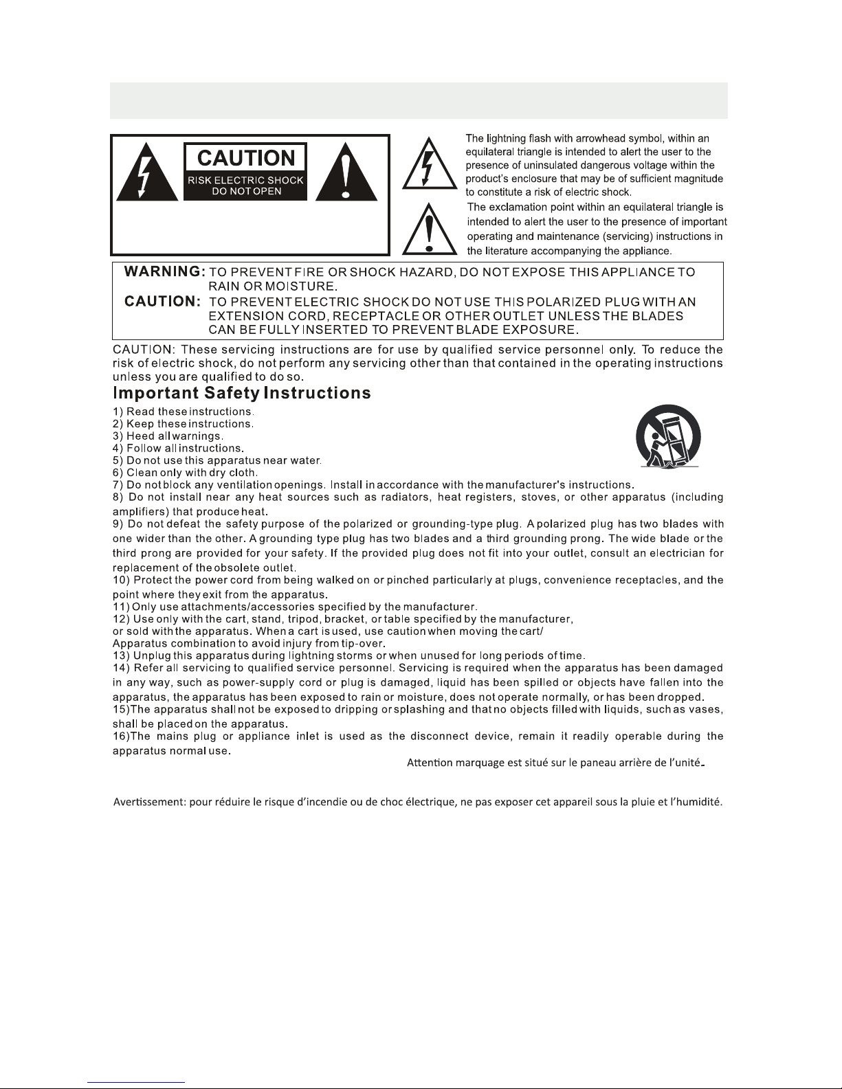
Caution marking is located at the rear of the apparatus.
The marking information is located at the rear of apparatus.
WARNING: To reduce the risk of fire or electric shock, do not expose this apparatus to rain or moisture.
WARNING: The battery (battery or batteries or battery pack) shall not be exposed to excessive heat such as sunshine, fire or
the like.
Le marquage est situé sur le paneau arrière de l’unité.
L'appareil ne doit pas être exposé aux écoulements ou aux éclaboussures et aucun objet ne contenant de liquide,
tel qu'un vase,ne doit être placé sur l'objet.
La prise du secteur est utilisé pour déconnecter le système. La prise du secteur ne doit pas être obstruée ou doit
être facilement accessible pendant son utilisation. Pour être complètement déconnecté de l’alimentation d’entrée,
la prise doit être débranchée du secteur.
Des pressions acoustiques excessives provenant découteurs ou de casques peuvent provoquer des pertes de
l’auditon.
Les piles ne doivent pas être exposées à de forte chaleur, tel qu'à la lumière du soleil, au feu ou autres choses de
semblable.
WARNING:Excessive sound pressure from earphones and headphones can cause hearing loss.
WARNING SHOCK HAZARD.DO NOT OPEN.
AVIS:RISOU DE CHOC ELECTRIQUE-NEPAS OUVRIR.
SAFETY PRECAUTION
1
ACCESSORIES
Please check and identify the supplied accessories.
.....................................................................................................................
................................................................................................................
...........................................................................................................
GETTING STARTED
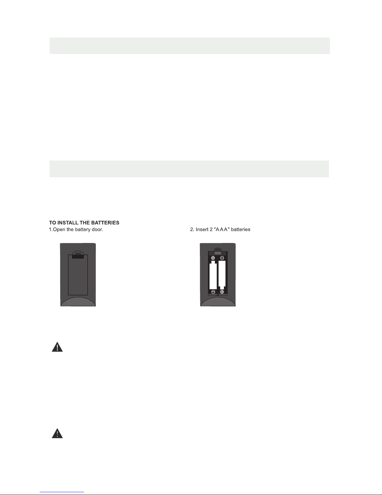
USING THE REMOTE CONTROL
BATTERY REPLACEMENT
CAUTION
: Danger of explosion if battery is incorrectly replaced.
NOTES
WARNING :
2
x 2
x 1
x 1
x 1
Remote control ..................................................................................................................
Remote control
Battery(AAA)
Warranty Card
Instruction Manual
·Point the remote control at the remote sensor located on the unit.
·When there is a strong ambient light source, the performance of the infrared remote sensor
·may be degraded, causing unreliable operation.
·The recommended effective distance for remote operation is about 16 feet (5 meters).
When the batteries become weak, the operating distance of the remote control is greatly
reduced and you will need to replace the batteries.
·If the remote control is not going to be used for a long time, remove the batteries to avoid
damage caused by battery leakage corrosion.
·Do not mix old and new batteries. Do not mix ALKALINE, standard (CARBON-ZINC) or
rechargeable (NICKEL-CADMIUM) batteries.
·Always remove batteries as soon as they become weak.
·Weak batteries can leak and severely damage the remote control.
Do not dispose batteries in a fire. Batteries may explode or leak.
Batteries shall not be exposed to excessive heat such as sunshine, fire or the like.
Base stand and 5 screws
...........................................................................................
x 1
Screw driver
................................................................................................................
x 1
CONTROL REFERENCE GUIDE
3
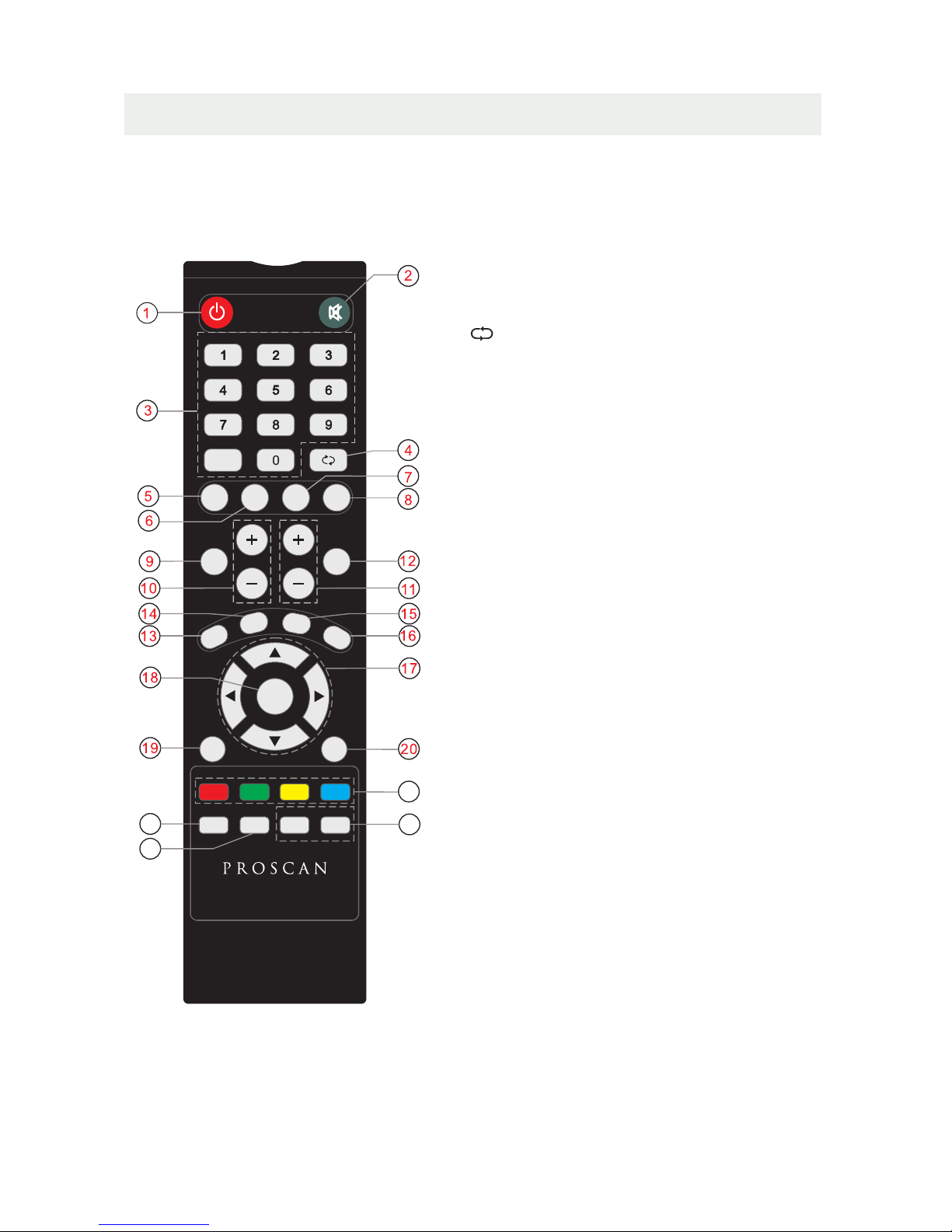
REMOTE CONTROL
1.STANDBY
To switch on the TV or make the TV into
standby mode.
2.MUTE
Press this button to mute or restore sound.
12.INFO
Show the information of the program you are watching.
9.SOURCE
Press this button to select an input source.
5.PMODE
Press this button to select a picture mode for different
picture qualities.
6.SMODE
Press this button to select sound setting for different
sound effects.
3.0-9
Allows you to change the channel of the TV.
4.
Switches back and forth between the current and
previous channels.
8.SLEEP
To select the amount of time before your TV turns
Off automatically.
10.VOL+/VOLIncreases/Decreases the Volume control.
11.CH+/CHSkips to the next/previous channel on TV mode.
17.UP/DOWN/LEFT/RIGHT
Moves the cursor upward/downward/to the left/to the right
when making a selection.
18.MENU
Displays the OSD Menu of the TV.
21.
No function.
7.MTS
To change among STEREO, MONO and SAP. If there is no
second language available for the signal received, LCD
Display audio will output to mono.
20.ENTER
Press to confirm selections on a menu screen.
19.Exit
Press this button to exit the on screen display.
13.EPG
Press this button to select the electronic programme
guide in DTV mode.
23. FAV
Press this button to show the favourite list.
24. FAV+/FAV-
Press this button to go through the FAV channel list.
14. CH.LIST
Display program list.
15. AUTO
Press to do auto configuration directly(PC MODE).
16. ASPECT
Select the aspect ratio settings:Wide/Zoom/Cinema/
Normal( ).In PC Mode:Wide/dot to dot
22.CC
Press the button to enter into the CC mode.
-
22
23
24
21
PMODE SMODE
MTS SLEEP
SOURCE
INFO
VOL CH
EPG
CH.LIST
AUTO
ASPECT
MENU
EXIT
ENTER
CC FAV FAV+ FAV-
CONTROL REFERENCE GUIDE
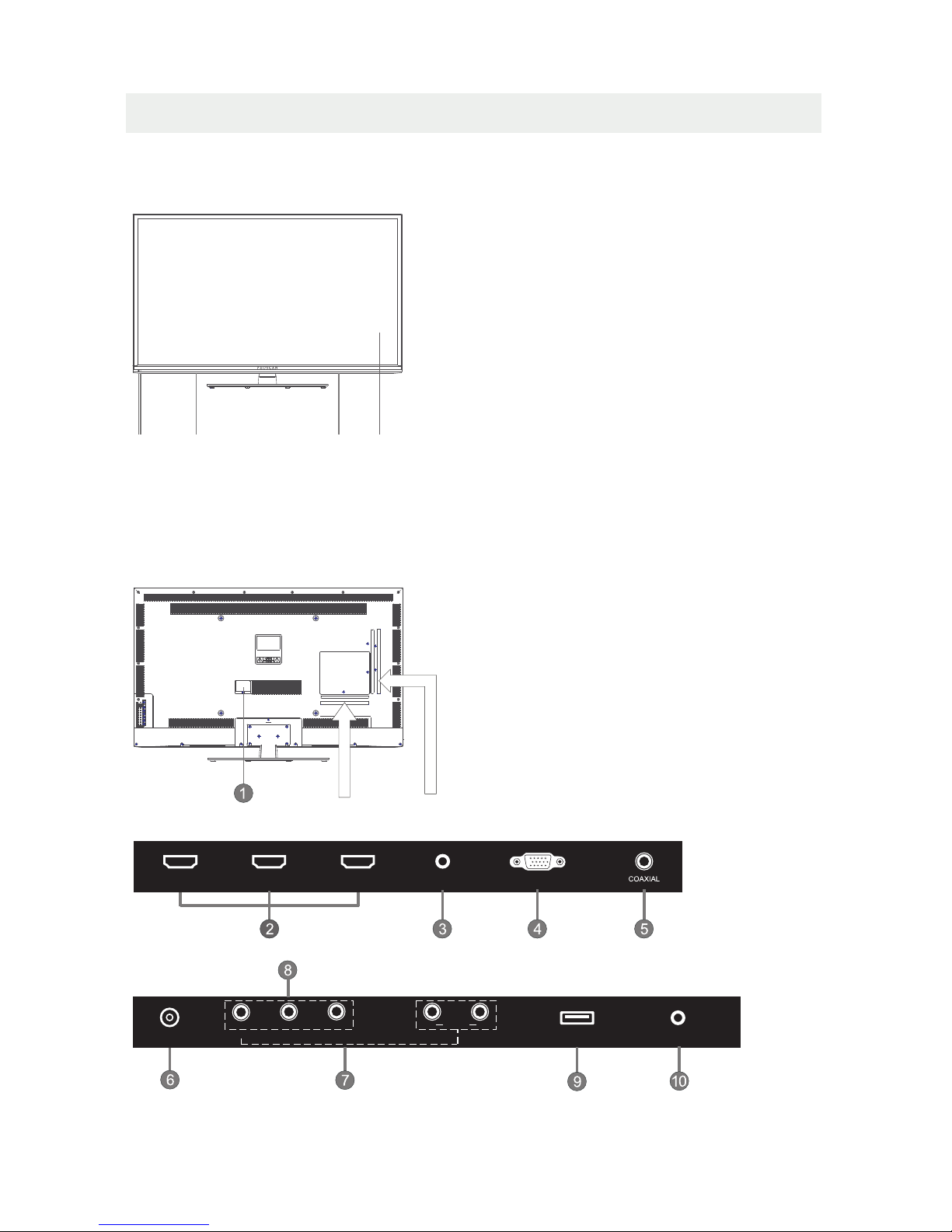
BACK VIEW
FRONT VIEW
1.Color Screen
2.Standby Indicator
Indicates whether the unit is ON
or in STANDBY (OFF) mode.
Light in red: The unit is in STANDBY.
Light in blue:The unit is turned ON.
3.Remote Sensor
Do not block this sensor or the
remote control will not work.
4. Speakers
4
1.Power cord
2.HDMI IN Jack
3.PC AUDIO IN Jack
4.VGA IN Jack
5.Coax OUT Jack
6.TV ANTENNA Terminal
7.AV (VIDEO/ AUDIO R/L) IN
8.COMPONENT IN Jack
9.Service Port
10.Headphone Jack
2
44
1
3
SERVICE PORT
Y
PRPB
R
L
AUDIO
RF
EARPHONE
VIDEO
AV IN
VGAPC AUDIO
HDMI2HDMI1 HDMI3
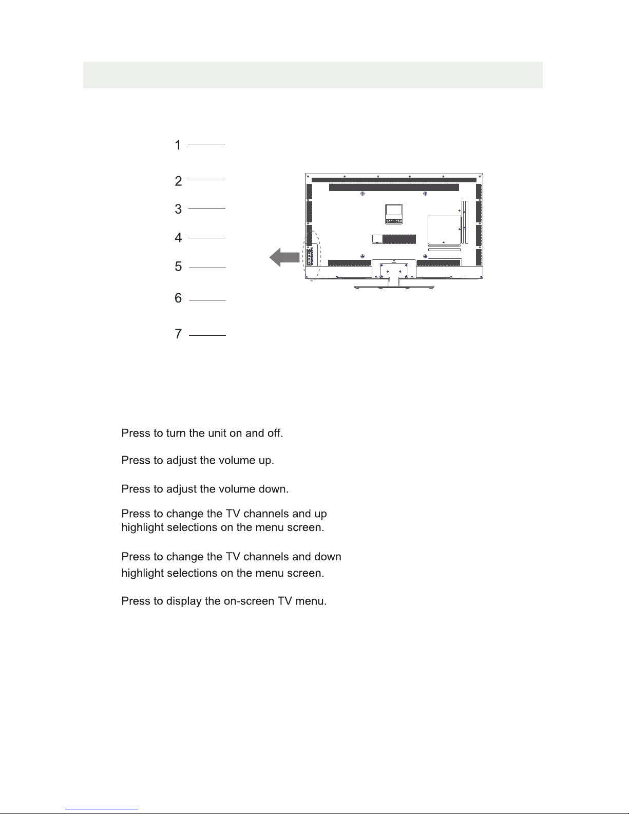
CONTROL REFERENCE GUIDE
5
VOL-
VOL+
CH-
CH+
MENU
SOURCE
STANDBY
Press to select the input source of the TV.
2. VOL+ Button
3. VOL- Button
4. CH+ Button
5. CH- Button
6. MENU Button
7. SOURCE Button
1. STANDBY Button
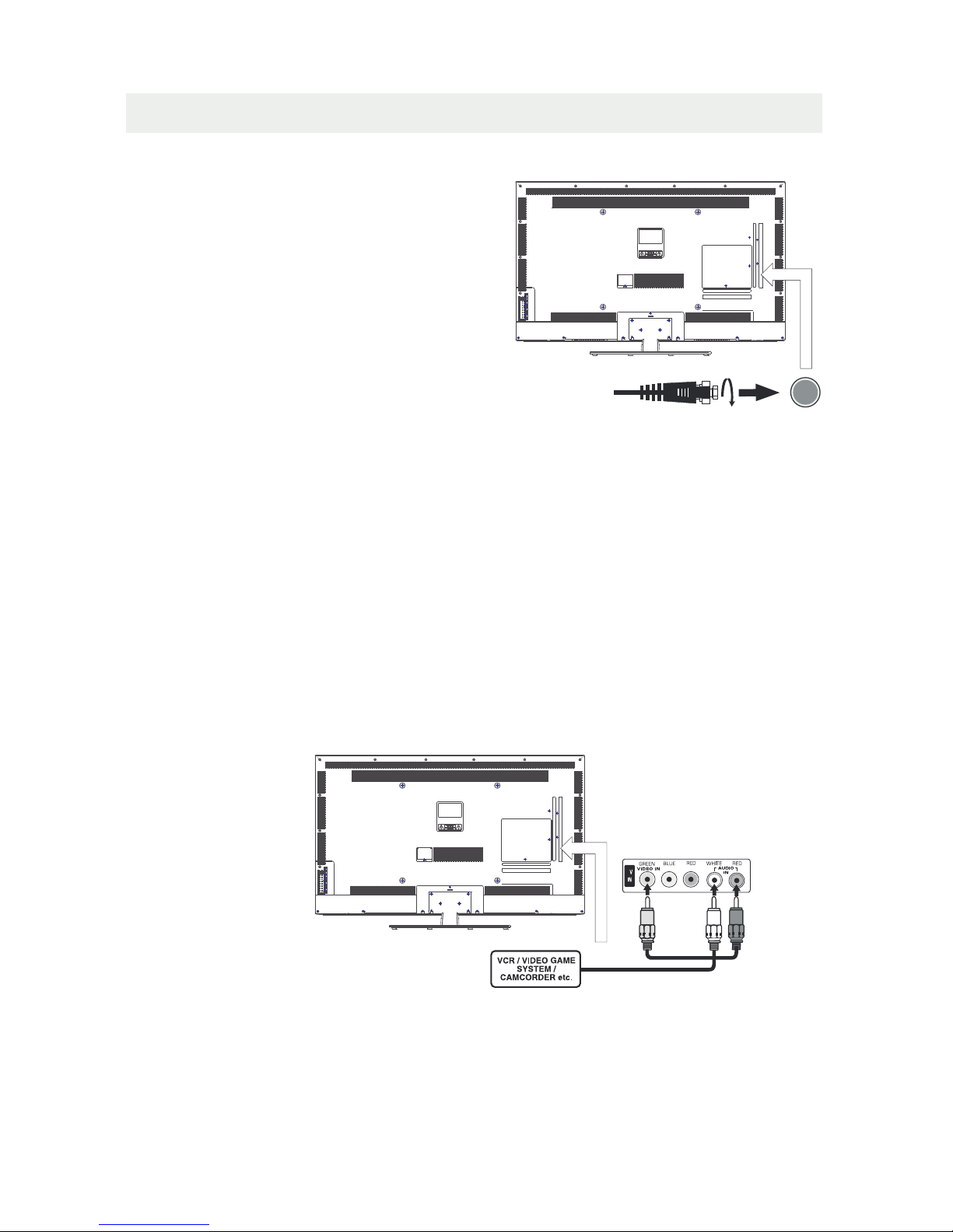
CONNECTIONS
CONNECTING A TV ANTENNA / CABLE / SATELLITE
To view television channels correctly, a signal must
be received from one of the following sources:
- An indoor or outdoor aerial antenna
- A cable system
- A satellite system
For receiving over-the-air TV broadcasts, we
recommend that you use an external fixed antenna.
Should you require the use of a temporary antenna,
please ensure that you purchase an antenna with
sufficient ability to receive in weak signal areas.
Only when you are in close proximity to a transmitter
will a temporary antenna reproduce a signal as
strongly as a fixed antenna.
To connect to other equipment such as a VCR, camcorder, satellite system or cable, etc.
CONNECTING AN A/V DEVICE
NOTE
CONNECTING DEVICES WITH A COMPOSITE (YELLOW RCA-TYPE)
VIDEO OUTPUT
Connecting to a VCR / Video Game System / Camcorder
AUDIO VIDEO OUT
NOTE
To connect A/V devices such as a VCR, video game system or camcorder.
Connect the AUDIO / VIDEO cable (not included) as shown.
Make sure you connect the cable from the other equipment ( and ) to this unit
Please refer to the user manual
for the other equipment for
more information.
Satellite, cable or TV antenna
cable to TV ANTENNA
terminal (cable not included)
6
(AV in)
To AUDIO / VIDEO
IN jacks
To AUDIO / VIDEO
OUT jacks
PbY Pr L R
A
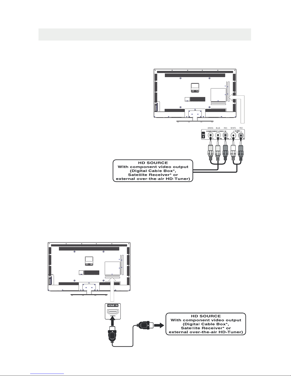
CONNECTIONS
CONNECTING A HIGH-DEFINITION (HD) SOURCE USING CONNECTION
NOTE
COMPONENT
High-Definition (HD) Devices with component video output must be connected to the Y input.
Connect the component video cable and audio cable (not included) as shown.
Make sure you connect the component video cable and audio cable from the other equipment
When connecting a DVD player to the television,
the picture resolution is solely dependent upon
the resolution supported by the DVD player attached.
DVD player resolutions vary from 480i to 1080p.
and this television can support DVD players up to
a maximum resolution of 1080p.
PbPr
* May require a subscription
for receiving HD channels,
check with your cable/satellite
service provider for details.
To COMPONENT
VIDEO OUT jacks
CONNECTING A HIGH-DEFINITION (HD) SOURCE USING HDMI CONNECTION
HDMI (High Definition Multimedia Interface) supports both video and audio on a single digital connection
for use with DVD players, DTV, set-topboxes and other digital AV devices. HDMI was developed to provide
the technologies of High Bandwidth Digital Content Protection (HDCP) as well asDigital Visual Interface
(DVI) in one specification. HDCP is used to protect digital content transmitted and received by
DVI-compliant or HDMIcompliant displays.
HDMI has the capability to support standard, enhanced or high-definition video plus standard to
multi-channel surround-sound audio. HDMI features include uncompressed digital video, a bandwidth of
up to 2.2 gigabytes per second (with HDTV signals), one connector (instead of several cables and
connectors), and communication between the AV source and AV devices such as DTVs.
To HDMI
IN jack
To HDMI
jackOUT
To COMPONENT
VIDEO IN jacks
To COMPONENT AUDIO
OUT jacks
Connect the HDMI cable (not included) as
shown:
Make sure you connect the cable from the
source equipment ( ) to this unit
( ).
HDMI OUT
HDMI IN
HDMI CABLE
(NOT INCLUDED)
(COMPONENT OUT and AUDIO OUT)to the unit COMPONENT IN.
COMPONENT IN
7
AUDIO IN jacks
To COMPONENT
 Loading...