

Model:PLDED4016A

CONTENTS
13
14
15
16
17
18
1
2
2
3
3
6
7
3
4
8
9
7
8
8
9
9
4
5
5
6
11
12
12
12
SAFETY
PRECAUTION
IMPORTANT
SAFETY
INSTRUCTION
ACCESSORIES
GETTING
STARTED
5
CONTROL
REFERENCE
GUIDE
WALL MOUNT
INSTALLATION
INITIAL SETUP
TV SETUP
CONNECTIONS
Remote Control
Front View
Back View
Front View
Antenna Connection
AV Connection
YPbPr Connection
HDMI Connection
VGA Connection
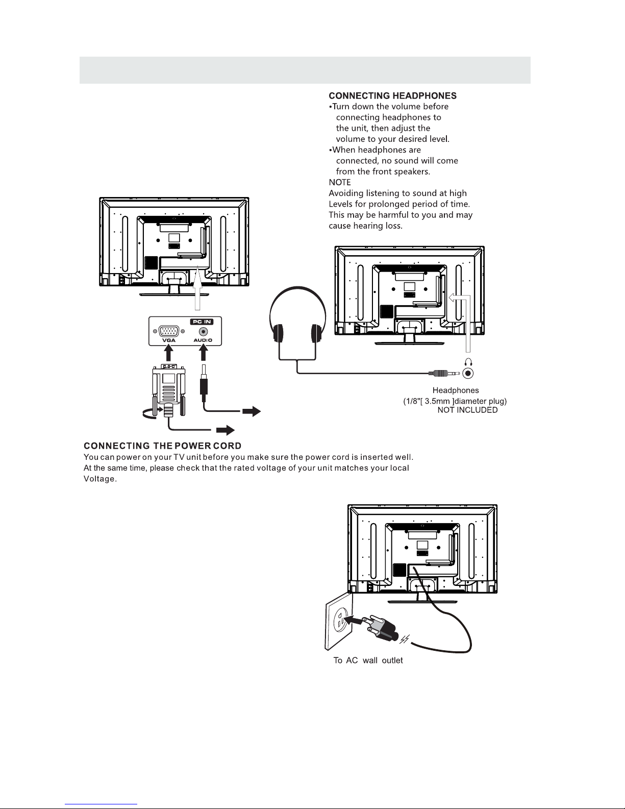
Headphone Connection
Power Cord Connection
Coax(SPDIF) Connection
Putting The Unit On A Proper Place
Source Selection
Turning The Unit On For The First Time
TV(CHANNEL) Menu
Picture Menu
Audio Menu
Time Menu
Setup Menu
LOCK(Parental) Menu
1
English
10
7
9

CONTENTS
19
10
21
11
12
22
DI S PLAY
MO D E
SP E CIFI C ATIO N
TR O UBLE SH O OTIN G
GU I DE
PC Formats
Video Formats
TV Symptom
SAFETY CLASS :This is an IEC safety class I product
and it must be grounded for safety.
20
*
SAFETY PRECAUTION
CAUTION
•
•
•
WAR NING:
PLACEMENT INFORMATION
SAFET Y INFORMATION
RATING PL ATE LOCATION
FCC STATEMENTS
WARNING:
1
CAUT ION M ARK ING W AS LO CAT ED AT THE REAR
OF THE A PPA RAT US.
WARNING: TO REDUCE THE RISK OF ELECTRIC
SHOCK,DO NOT REMOVE COVER(OR BACK)
NO USER SERVICEABLE PARTS INSIDE.
REFER SERVICING TO QUALIFIED SERVICE
PERSONNEL.
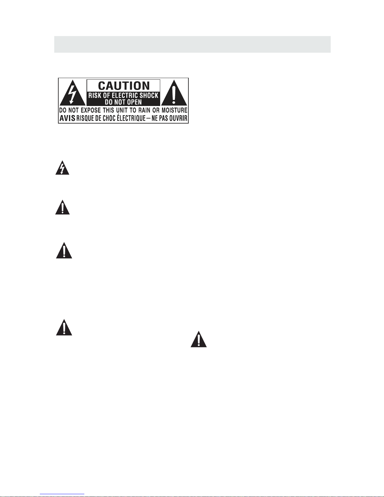
The lightning flash with arrowhead symbol,
within an equilateral triangle,is intended to
alert the user to the presence of uninsulated
“dangerous voltage”within the product's enclosure
that may beof sufficient magnitude to constitute a
risk of electric shock to persons.
The exclamation point within an equilateral
Triangle is intended to alert the user to
The presence of important operating and
maintenance (servicing) instructions in the literature
accompanying the appliance.
DANG ER OF E XPL OSI ON IF BATTER Y IS
INCO RRE CTL Y REP LAC ED. REP LAC E ONL Y
WITH T HE SA ME OR E QUI VALENT TYP E.
USE OF C ONT ROL S OR AD JUSTMENT S OR
PERF ORM ANC E OF PR OCEDURES O THE R
THAN T HOS E SPE CIF IED MAY RESU LT IN
HAZA RDO US RA DIA TION EXPOS URE .
•
•
TO RED UCE T HE RI SK OF F IRE OR ELECT RIC
SHOC K, DO N OT EX POS E THIS APPLI ANC E TO
RAIN O R MOI STU RE.
TO REV ENT F IRE O R SHO CK HAZARD, D O NOT
EXPO SE TH IS UN IT TO R AIN OR MOIST URE . DO
NOT PL ACE O BJE CTS F ILLED WITH L IQU IDS O N
OR NEA R THI S UNI T.
SHOU LD AN Y TRO UBL E OCC UR, DIS CON NEC T
THE AC P OWE R COR D AND R EFER SERVI CIN G
TO A QUA LIF IED T ECH NICIAN.
Do not u se th is un it in p lac es that are ex tre mel y
hot, c old , dus ty or h umi d.
Do not r est ric t the a irflow of th is un it by p lac ing i t
some whe re wi th po or ai rflow, by co ver ing i t wit h
a clot h, by p lac ing i t on be dding or car pet ing .
When c onn ect ing o r dis connecti ng th e AC po wer
cord , gri p the p lug a nd no t the cord its elf . Pul lin g
the co rd ma y dam age i t and c reate a haza rd.
When y ou ar e not g oin g to us e the unit for a l ong
peri od of t ime , dis con nect th e AC po wer c ord .
The ra tin g pla te is l oca ted on the rea r of th e uni t.
NOTE : Thi s uni t has b een tested a nd fo und t o com ply
with t he li mit s for a C las s B digit al de vic e, pu rsu ant
to Par t 15 of t he FC C Rul es. These li mit s are d esi gne d
to pro vid e rea son abl e protecti on ag ain st ha rmful
inte rfe ren ce in a r esi dential in sta lla tio n.
This u nit g ene rat es, u ses and can ra dia te ra dio
freq uen cy en erg y and , if not insta lle d and u sed i n
acco rda nce w ith t he in structio ns, m ay ca use h armful
inte rfe ren ce to r adi o communic ati on. H owe ver, there
is no gu ara nte e tha t int erferenc e wil l not o ccu r in a
part icu lar i nst all ation. If th is un it do es ca use harmfu l
inte rfe ren ce to r adi o or televis ion r ece pti on, which
can be d ete rmi ned b y tur ning the uni t off a nd on , the
user i s enc our age d to tr y to corr ect t he in ter fer ence
by one o r mor e of th e fol low ing measur es:
- Reor ien t or re loc ate t he receivi ng an ten na.
- Incr eas e the s epa rat ion betwee n the u nit a nd
rece ive r.
-Con nec t the u nit i nto a n outlet on a ci rcu it di ffe rent
from t hat t o whi ch th e receiver i s con nec ted .
- Cons ult t he de ale r or an e xperienc ed ra dio /TV
tech nic ian f or he lp.
Changes or m odi fic ati ons to this
unit not exp res sly a ppr oved by the part y res pon sib le
for compli anc e cou ld vo id the user auth ori ty
to operate t he un it.
•
•
•
•

IMPORTANT SAFETY INSTRUCTIONS
2
1)Rea d the se in str uct ions.
2)Kee p the se in str uct ions.
3)Hee d all w arn ing s.
4)Fol low a ll in str uct ions.
5)Do no t use t his a ppa rat us near wate r.
6)Cle an on ly wi th a dr y clo th.
7)Do no t blo ck an y ven til ation open ing s.
Inst all i n acc ord anc e with the
manu fac tur er' s ins truction s.
8)Do no t ins tal l nea r any h eat source s suc h
as rad iat ors , hea t reg isters, st ove s, or
othe r app ara tus ( Inc luding amp lif ier s) th at
prod uce h eat .
9)Do no t def ect t he sa fet y purpose of t he
pola riz ed or g rou ndi ng-type pl ug.
A pola riz ed pl ug ha s two b lades with o ne
wide r tha n the o the r.
A grou ndi ngt ype p lug h as two blade s
and a th ird g rou ndi ng pr ong.
The wi de bl ade o r the t hir d prong is
prov ide d for y our s afe ty.
If the p rov ide d plu g doe s not fit into y our
wall o utl et, c ons ult a n electric ian f or
repl ace men t of th e obs olete outl et.
10)Pr ote ct th e pow er co rd from bein g wal ked o n
or pin che d par tic ula rly at plugs , con ven ien ce
rece pta cle s, an d the p oint where t hey e xit
from t he ap par atu s.
11)On ly us e att ach men ts / accesso rie s spe cif ied
by the m anu fac tur er.
12)Us e onl y wit h the c art , stand,
trip od, b rac ket , or ta ble
spec ifi ed by t he ma nuf acturer,
or sol d wit h the a ppa rat us.
When a c art i s use d, us e cau tion when
movi ng th e car t / app ara tus combin ati on to
avoi d inj ury f rom t ip- over.
13)Un plu g thi s app ara tus during l igh tni ng
Stor ms or w hen u nus ed fo r long perio ds of
time .
14)Re fer a ll se rvi cin g to qualifi ed se rvi ce
pers onn el. S erv ici ng is requir ed wh en th e
appa rat ush as be en da maged in any w ay,
such a s the p owe r cor d or pl ug is damage d,
liqu id ha s bee n spi lle d or objects h ave f all en
into t he ap par atu s, th e apparatu s has b een
expo sed t o rai n or mo ist ure, does no t ope rat e
norm all y, or h as be en dr opped.
15)To p rev ent e lec tri c shock, ens ure t he gr oun din g
pin on t he AC c ord p owe r plu g is securel y
conn ect ed.
ACCESSORIES
Please check and ide ntif y the supplied accessories.
..... ... ... ... ....... ... ... ... ....... ... ... ... ....... ... ... ... ....... ... ... ... ....... ... ... ... ....... ... ... . ..... ... .
..... ... ... ... ....... ... ... ... ....... ... ... ... ....... ... ... ... ....... ... ... ... ....... ... ... ... ....... ... ... ... ..
..... ... ... ... ....... ... ... ... ....... ... ... ... ....... ... ... ... ....... ... ... ... ....... ... ... ... ....... ... ...
GETTING STARTED
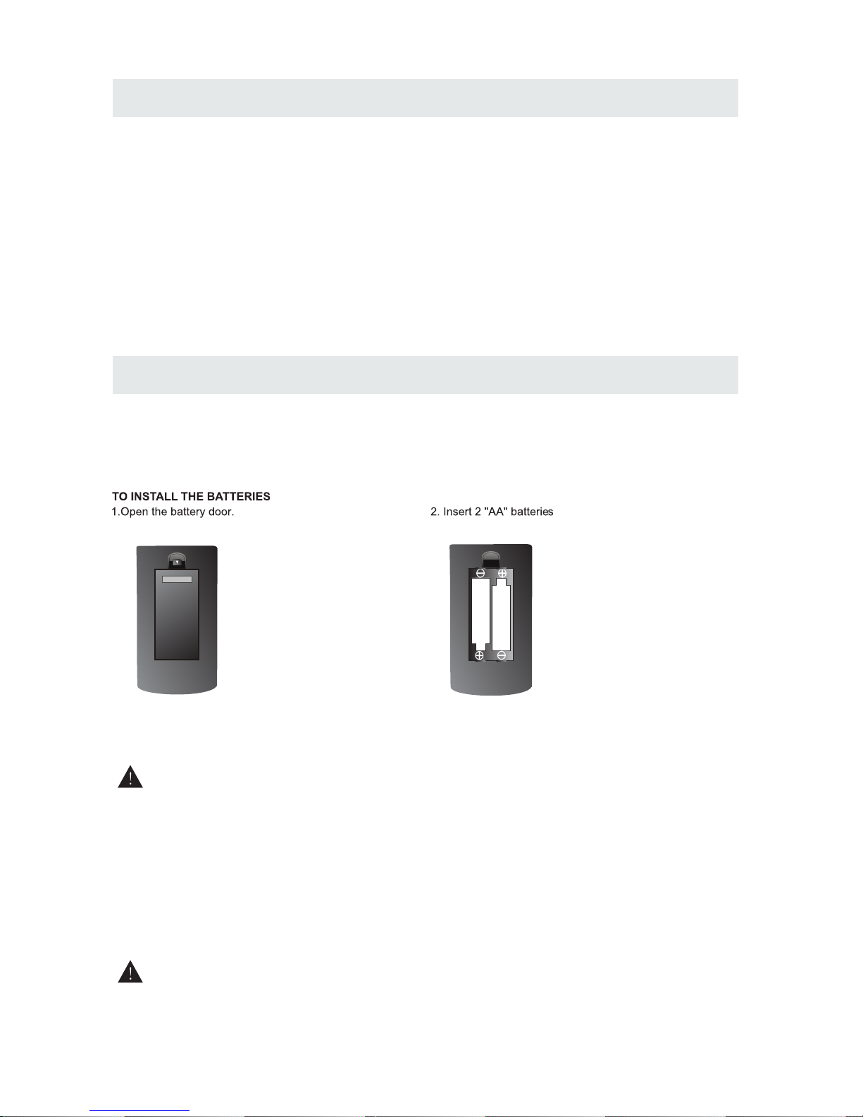
USING THE REMOTE CONTROL
BATTERY REPLACEMENT
CAUTION
: Da nge r of e xplo sio n if ba tter y is in cor rec tly r epl ace d.
NOT ES
WARNING :
3
x 2
x 1
x 1
x 1
Remo te co ntr ol .. ..... ... ... ... ........ ... ... ........ ... ... ........ ... ... ........ ... ... ........ ... ... ........ ... ... ........ ... ...
Remo te co ntr ol
Batt ery (AA )
Warr ant y Car d
Inst ruc tio n Man ual
·Poin t the r emo te co ntr ol at t he remote se nso r loc ate d on th e uni t.
·When t her e is a st ron g amb ien t light sour ce, t he pe rfo rma nce o f the infrar ed re mot e sen sor
·may be d egr ade d, ca usi ng un reliable oper ati on.
·The re com men ded e ffe cti ve distanc e for r emo te op era tio n is about 16 fe et (5 m ete rs) .
When t he ba tte rie s bec ome w eak, the operat ing d ist anc e of th e rem ote contro l is gr eat ly
redu ced a nd yo u wil l nee d to re pla ce the batte rie s.
·If the r emo te co ntr ol is n ot go ing to be used for a lo ng ti me, r emo ve th e bat teries to av oid
dama ge ca use d by ba tte ry le aka ge corrosi on.
·Do not m ix ol d and n ew ba tte rie s. Do not mix ALKAL INE , sta nda rd (C ARB ON-ZINC) o r
rech arg eab le (N ICK EL- CAD MIUM) batt eri es.
·Alwa ys re mov e bat ter ies a s soon as they beco me we ak.
·Weak b att eri es ca n lea k and s everely damag e the r emo te co ntr ol.
Do not d isp ose b att eri es in a f ire. Batte rie s may e xpl ode o r lea k.
Batt eri es sh all n ot be e xpo sed to exces siv e hea t suc h as su nsh ine, fire or the li ke.
Base stand and 5 screws
..... ... ... ... ....... ... ... ... ....... ... ... ... ....... ... ... ... ....... ... ... ... ....... ... ...
x 1
Screw driver
..... ... ... ... ....... ... ... ... ....... ... ... ... ....... ... ... ... ....... ... ... ... ....... ... ... ... ....... ... ... ... ..
x 1
CONTROL REFERENCE GUIDE
4
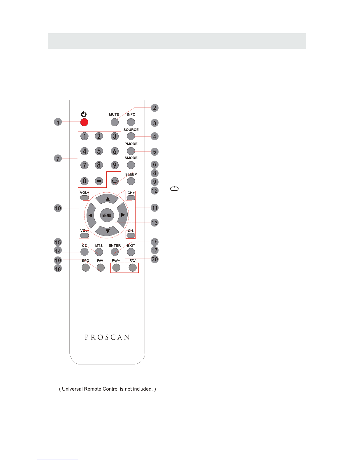
REMOTE CONTROL
Universal Remote Code: 1218
1.STANDBY
To switch on the TV or make the TV into
standby mode.
2.MUTE
Press this button to mute or restore sound.
3.INFO
Show the information of the program you are watching.
4.SOURCE
Press this button to select an input source.
5.PMODE
Press this button to select a picture mode for different
picture qualities.
6.SMODE
Press this button to select sound setting for different
sound effects.
7.0-9
Allows you to change the channel of the TV.
8.
Switches back and forth between the current and
previous channels.
9.SLEEP
To select the amount of time before your TV turns
Off automatically.
10.VOL+/VOLIncreases/Decreases the Volume control.
11.CH+/CHSkips to the next/previous channel on TV mode.
12.UP/DOWN/LEFT/RIGHT
Moves the cursor upward/downward/to the left/to the right
when making a selection.
13.MENU
Displays the OSD Menu of the TV.
14.CC
Press the button to enter into the CC mode.
15.MTS
To change among STEREO, MONO and SAP. If there is no
second language available for the signal received, LED
Display audio will output to mono.
16.ENTER
Press to confirm selections on a menu screen.
17.Exit
Press this button to exit the on screen display.
18.EPG
Press this button to select the electronic programme
guide in DTV mode.
19. FAV
Press this button to show the favourite list.
20. FAV+/FAVPress this button to go through the FAV channel list.
CONTROL REFERENCE GUIDE
FRONT VIEW
5
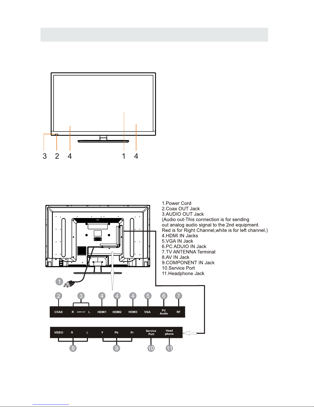
BACK VIEW
1.Color Screen
2.Remote Sensor
Do not block this sensor or the
remote control will not work.
3.Standby Indicator
Indicates whether the unit is ON
or in STANDBY (OFF) mode.
Light in red: The unit is in STANDBY.
Light in blue:The unit is turned ON.
4. Speakers
CONTROL REFERENCE GUIDE
6
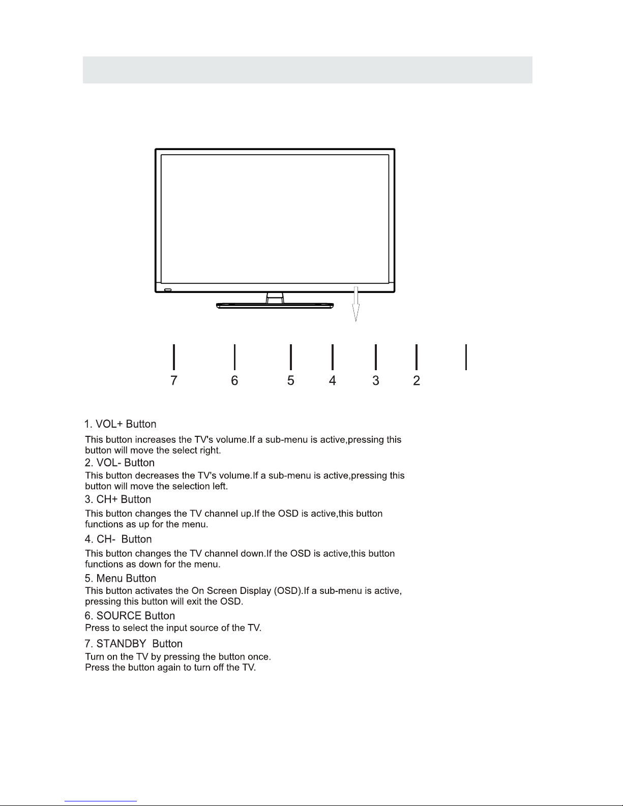
FRONT VIEW
1
VOL+
STANDBY SOURCE
MENU
CH- CH+ VOL-
CONNECTIONS
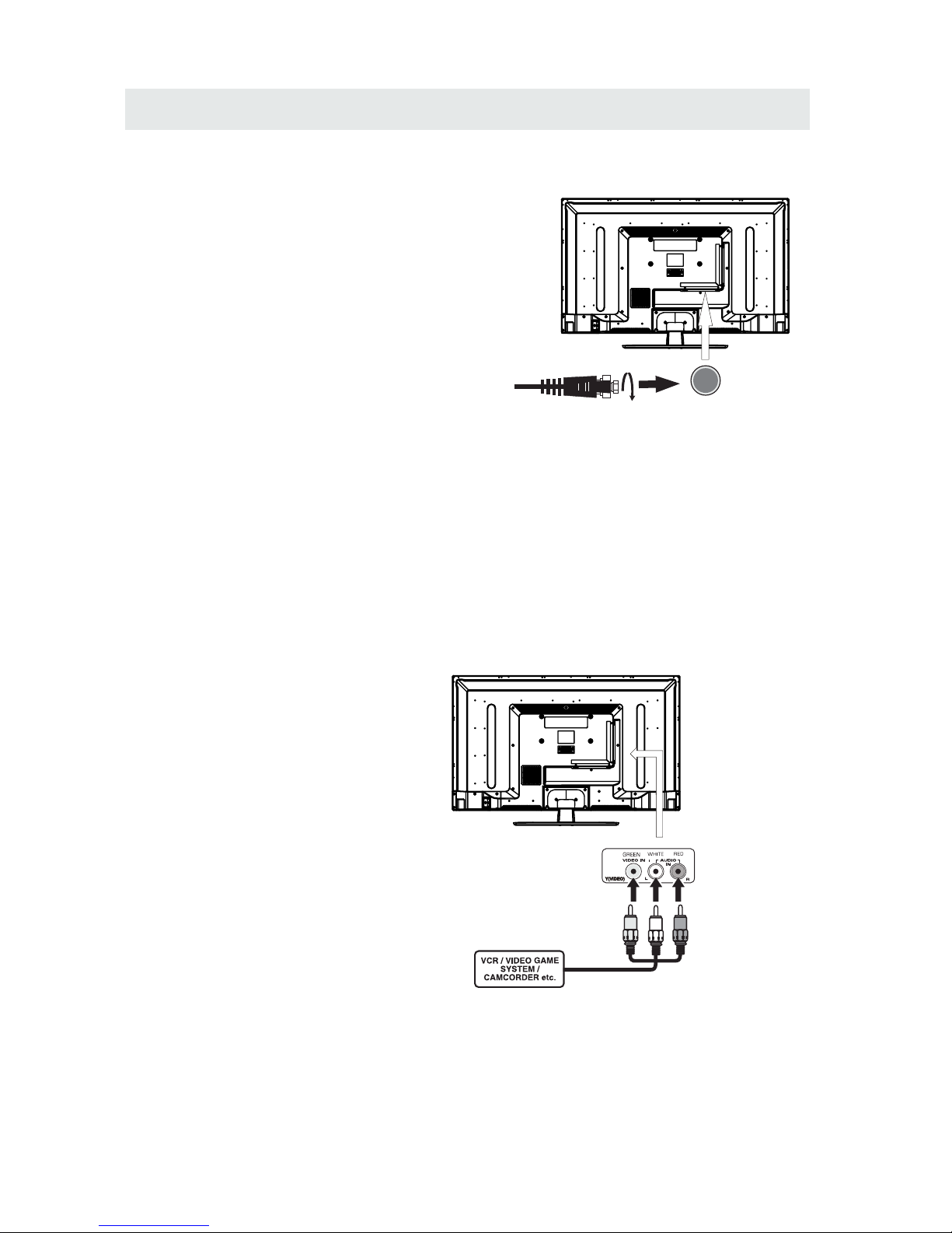
CONNECTING A T V ANTENNA / CABLE / S A TELLITE
To view tel evis ion cha nnel s corre ctly, a signa l must
be recei ved from one of the follow ing sou rces:
- An indoor or outdoo r aerial anten na
- A ca ble sy ste m
- A sate llite syste m
Fo r rece iving over-t he-a ir TV broa dcas ts, we
recom mend th at yo u use an e xter nal fixed an tenn a.
Sh ould y ou re quire the us e of a te mpor ar y ante nna,
pl ease en sure that you pu rcha se an antenna wit h
su ffic ient ab ilit y to rece ive in wea k signa l areas .
On ly whe n you are in cl ose proximity to a trans mitter
wi ll a tempo rar y anten na reprodu ce a si gnal as
st ron gly as a fixed an tenn a.
To conne ct to othe r equip ment su ch as a VCR, camc ord er, sat elli te system or cabl e, etc .
CONNECTING AN A/V DEVICE
NOTE
CONNECTING DEVICES WITH A COMPOSITE
VIDEO OUTPUT
Connecting to a VCR / Video Game System / Camcorder
AUDIO VIDEO OUT
NOTE
To con nect A /V devi ces su ch as a VCR, vi deo ga me sys tem or c amcorder.
Co nnec t the AUDIO / VIDEO cabl e (not inc lude d) as show n.
Ma ke sure yo u conn ect th e cable f rom t he other equi pmen t ( and ) to this u nit
1 P. lease refer to the us er manu al.
fo r the ot her eq uipment for
mo re inf ormation.
Sa te llite, cable or TV antenna
ca ble t o TV ANTENN A
term inal (c abl e not inc lud ed)
7
(AV in)
2. Comp osite vid eo inp ut
(shar ed with com pone nt)
To AU DI O / VIDE O
IN j ac ks
To AUDI O / VIDEO
OU T jac ks
CONNECTIONS
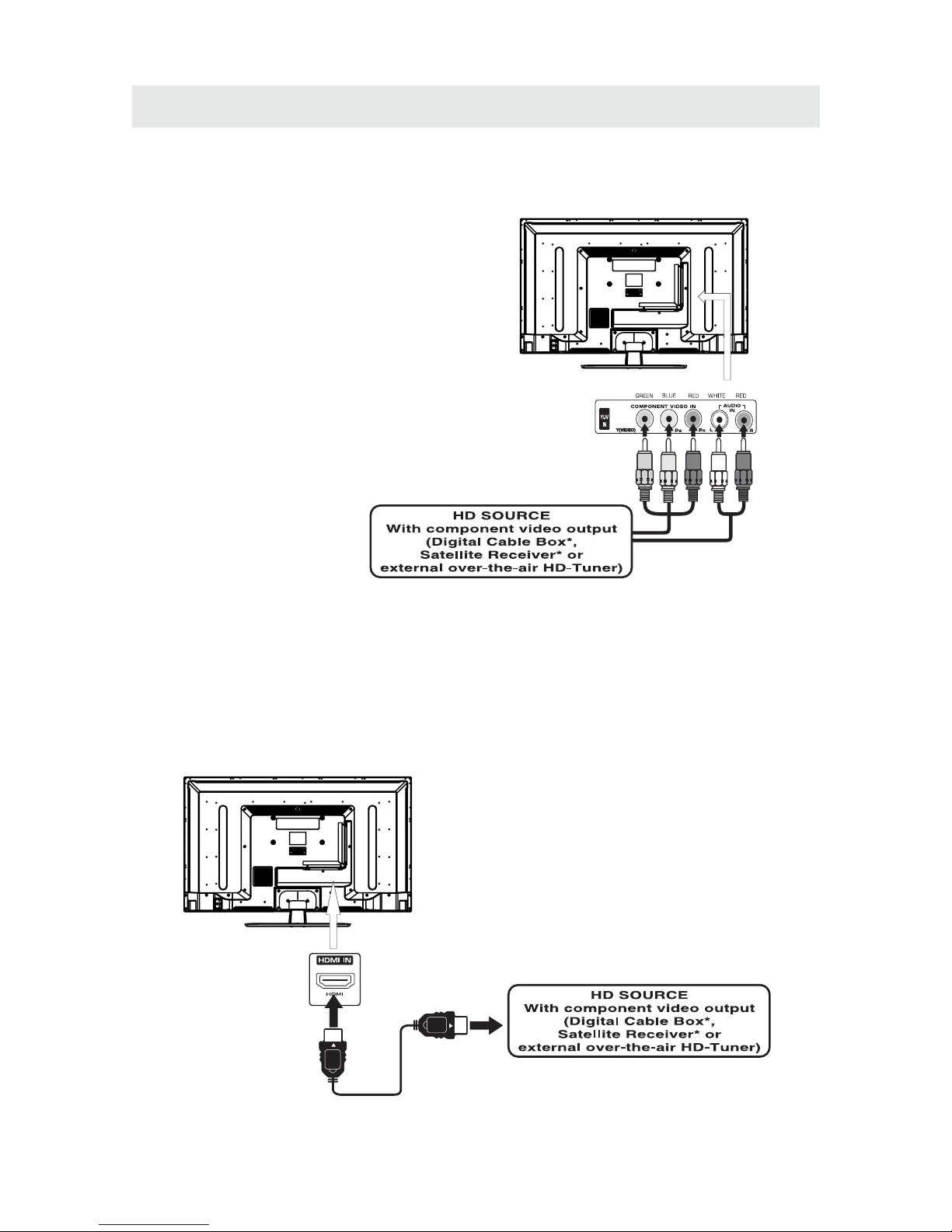
CONNECTING A HIGH-DEFINITION (HD) SOURCE USING CONNECTION
NOT E
COMPONENT
High-Definition (HD) Devi ces wi th com pon ent vi deo ou tpu t must be co nne cted to the Y input .
Connect the comp one nt vid eo cab le and au dio ca ble (n ot inc lud ed) as sh own .
Ma ke s ure you co nne ct th e com pone nt vi deo c abl e and au dio c abl e from the o the r equipm ent
When con nect ing a DVD player to the telev isio n,
the pict ure resol utio n is solel y depen dent up on
the resolution sup porte d by the DVD player attach ed.
DVD play er res olut ions var y from 48 0i to 108 0i.
and this telev isio n can supp ort DVD pla yers up to
a maximu m resoluti on of 108 0i.
PbPr
* May require a s ubscription
fo r recei ving HD ch annel s,
ch eck wit h your cable/s atel lite
se r v ice pro vide r fo r detai ls.
To COMP ONEN T
VI DEO O UT ja cks
CONN ECTING A HIGH-DEFINITION (HD) SOURC E USING HDMI CONNECTION
HDMI (Hi gh Def ini tio n Mult ime dia In ter f ace ) supp orts both video and aud io on a si ngl e digi tal co nne cti on
fo r use w ith D VD pl aye r s, DTV, set- top box es an d oth er di gita l AV dev ice s. HD MI wa s develop ed to p ro vide
the tec hno logies of High Ban dwi dth Di gital Conten t Prot ect ion (H DCP ) as well as D igi tal Vis ual In ter face
(D VI) i n one s pec ific ati on. H DCP i s use d to pr otect di git al co nte nt tr ansm itted an d re ceived b y
DVI-c omp lia nt or HDM Ico mpl ian t disp lays .
HDMI has the capabi lity to supp ort stan dard, en han ced or hi gh- def inition vi deo pl us sta nda rd to
multi -ch ann el sur rou nd- sou nd aud io. HD MI fea tur es inc lud e unco mpress ed dig ita l video , a ba ndw idt h of
up to 2.2 gig aby tes pe r seco nd (with HDTV signals ), one co nne cto r (ins tea d of sev era l cabl es and
conne ctors) , and com mun ica tio n betw een the AV sourc e and AV devices such as DTVs.
To HDMI
IN jack
To HDMI
ja ckOUT
To COMPONENT
VIDEO IN jacks
AU DIO I N jack s
To COMPONENT AUDIO
OU T jac ks
Co nne ct th e HDM I cable (no t inc lud ed) a s
sh own :
Ma ke s ure you co nne ct th e cab le from th e
so urce equi pme nt ( ) to this uni t
( ).
HD MI OUT
HD MI IN
HDMI CABLE
(NOT INCLUDED)
(COMPONENT OUT and AUDIO OUT)to the unit COMPONENT IN.
COMPONENT IN
8
To COMPONENT
CONNECTIONS
CONNECTING A
AUDI O - PC OU T
VGA AUDI O - PC IN
PC
VGA
Co nne ct the 15 -pi n D-SU B PC/VGA con nec tor
from yo ur computer to the 15 -pi n D- SUB PC /VGA
in put on th is uni t usin g a monitor cab le and an
au dio ca ble (n ot inc lud ed) as sho wn.
Ma ke s ure you co nne ct th e cab le from th e computer
( an d ) to this unit
( and ) .
TO PC Connector
TO AUDI O OUT jacks
NOT E
• Inser t the power plu g full y into the socket outlet
If the pow er plu g is loose it could ge ner ate heat and
cause fire
Do not touc h the powe r plug with a wet hand
This may cause electrical shock
Do not use an y power cord othe r than that provided
with this TV This may cause fire or el ect ric al sho ck
Do not damage the powe r cord
A damaged cord may ca use fire or electr ical sho ck
• Do not move the TV with the cord plugged in the
socket outlet.
• Do not place a heav y object o n the cord or place
the cord near a high-temperature obj ect.
• Do not twist the cord, ben d it excessively, or stretch it.
• Do not pul l on the cord. Hold onto the power plug body when disconnecting cord.
• Do not use a damage d power plug or s ocket outlet.
.
( ,
.)
.
( .)
. ( .)
.
( ).
•
•
•
connected to prevent electrical shock.
Ensure that the power plug is easily accessible.
Ensure the earth pin on the power plug is securely
•
•
9
CONNECTIONS
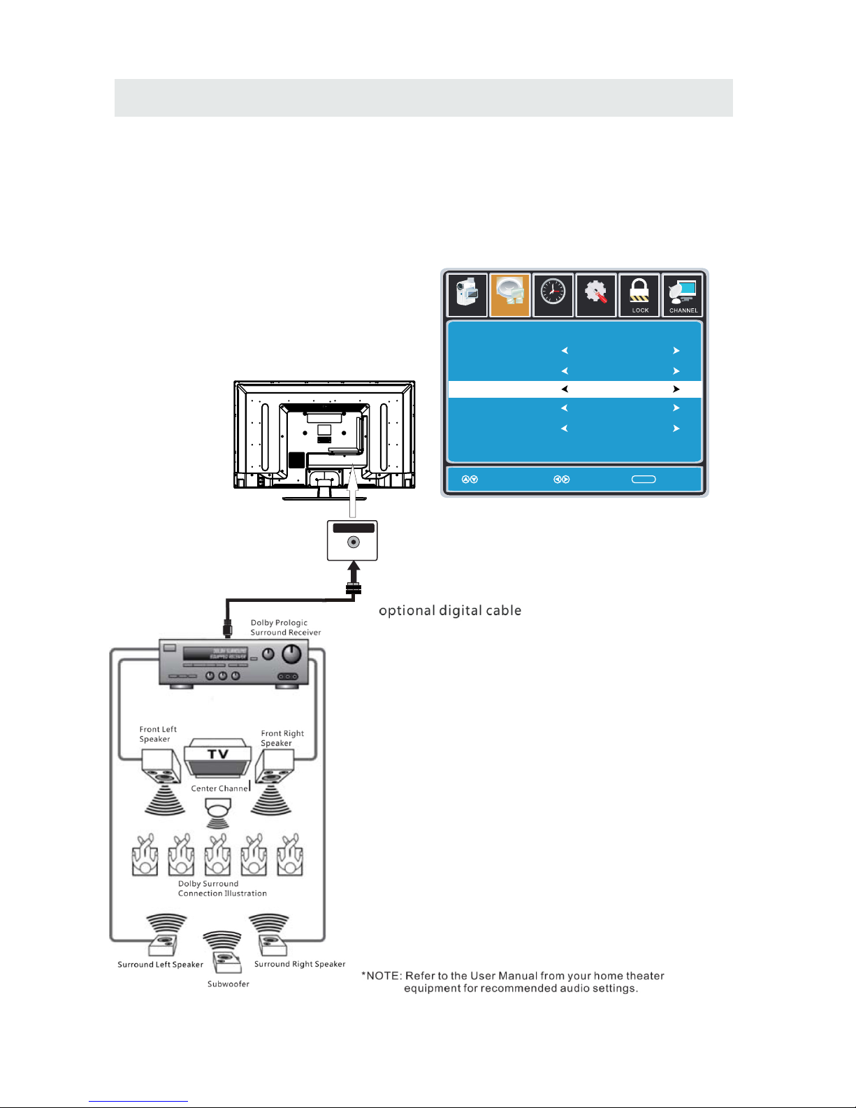
Connection to a Home Theater Audio System
For BEST audio performance
Connecting to a Home Theater System
Dolby Digital can deliver optimal 2 channel
stereo or surround sound with five discrete
full range channels plus a sixth channel for
a subwoofer.
Enjoy optimal sound reproduction from your
system with a Dolby Digital amplifier that
incorporates a digital coaxial input. Connect
an optional digital cable directly to the
television’s Coax audio output to listen
through all inputs except VGA.
(The VGA does not support digital audio)
How To Setup Digital Output
Press the MENU button on the remote control
Press the right ► arrow button to select sound
Press the down ▼ arrow button to highlight
SPDIF type right ► Raw or PCM
10
Coax
SPD IF OUT
Set up
12
6
Tim
e
Equa lizer S ettin gs
MTS
Audio Language
AVL
Surround Sound
Move Select Exit
MEN U
Off
Pict ure
Sound
Englis h
Digi ta l Audi o Ou tput
PCM
Off
Stereo
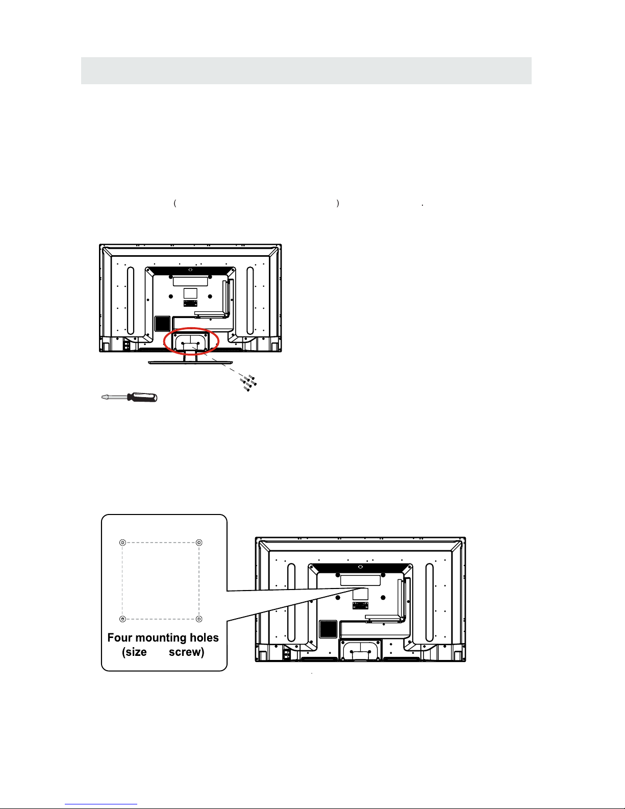
WALL MOUNT INSTALLATION
INSTALLI NG REMOVING THE BASE STAND
WAR NING/: The LED Di spl ay is ve ry fr agi le an d mus t be prote cte d a t all t ime s whe n rem ovin g the b ase
Stan d
Be sure th at no hard or sharp object or anything that could scratch or damage the LE D display com es into
contact with it Do NOT e xert pres sure on the front of th e unit at any time because t he sc reen could crack
1 Disconnect all cabl es or cords connected to the unit
2 Lay the unit down on a fl at su rface wit h the back side facing up Ple ase make sure to place a soft
cushioned material such as a pill ow or thi ck pie ce of foam beneath the screen
3 To remove the bas e sta nd loosen screws off the holes then p ull down wards to release
the base st and
,
.
. .
. .
. .
. ,
MO UNT ING ON TH E WAL L
NOT E
Remo ve the base st and be fore moun ting th e unit on th e wall .
This unit is VESA-compliant, and is de signed to be wall- mou nte d with a VESA-c omp liant 8”x 4 ”
(200mm x 100mm) mounting kit designed for fla t-pan el TVs (not suppl ied ). Mount this unit according to
the instructions included in the mount ing kit.
Length of screw should not exceed 10 mm.
11
8”
4”
M5
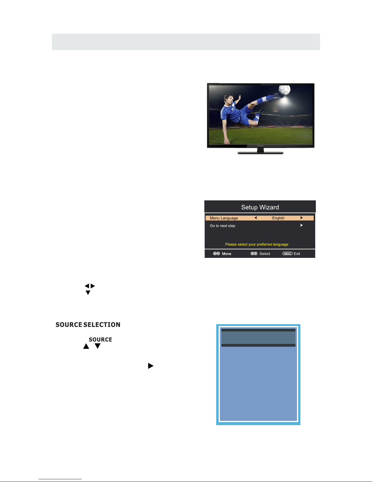
INITIAL SETUP
Wh en you t urn on your tel evision set f or
th e first t ime, be s ure t o place i t on a sol id
st able su r face.
To avo id danger, do n ot exp ose the T V
to wate r, or a he at source
(e .g. lam p, candl e, radiator) .
Do not obstr uct the ven tila tion gri d
at t he re ar and be s ure to leave s uffic ient
ga ps arou nd the uni t.
PUT TING THE UNIT ON A PROPER PLACE
TU R N ING THE UNIT O N F OR THE FIRST TI M E
Af ter you have initi ally conne cted you r TV
antenna o r c able,
tu rn the telev ision ON .
A screen wil l displ ay asking you to ru n a
to se arch and receive
availa ble loca l digital ch annel s.
It is he re where you will sele ct antenn a option s
an d run .
Channel s w ill be stored in th e TV tune r .
Press the bu tton on the remote co ntrol.
Pr ess the button to highli ght AIR/ CABLE .
Ch a nne l Au to Scan
Ch a nne l Au to Scan
ME N U
Using the buttons, scroll to highlight chaneel mode.
1. Press the butto n on the remo te cont rol.
2.
and selec t a ny of th e m using the butt on or
the button.
ource
Note:
Be fore watch ing ple ase make sure all necess ary
cables and devic es are connected.
ENT ER
Us e or button to sel ect th e optio nsthe
(T he screen wi ll chan ge to your des i red s ).
(TV,AV,YPbPr,HDMI1,HDMI2,HDMI3,PC)
12
Source Select
TV
AV
YPbPr
HDMI1
HDMI2
HDMI3
PC
 Loading...