

Page 1

EP6585
65
Page 2

Page 3

TV Base Stand assemble
18
18
12
17
17
18
18
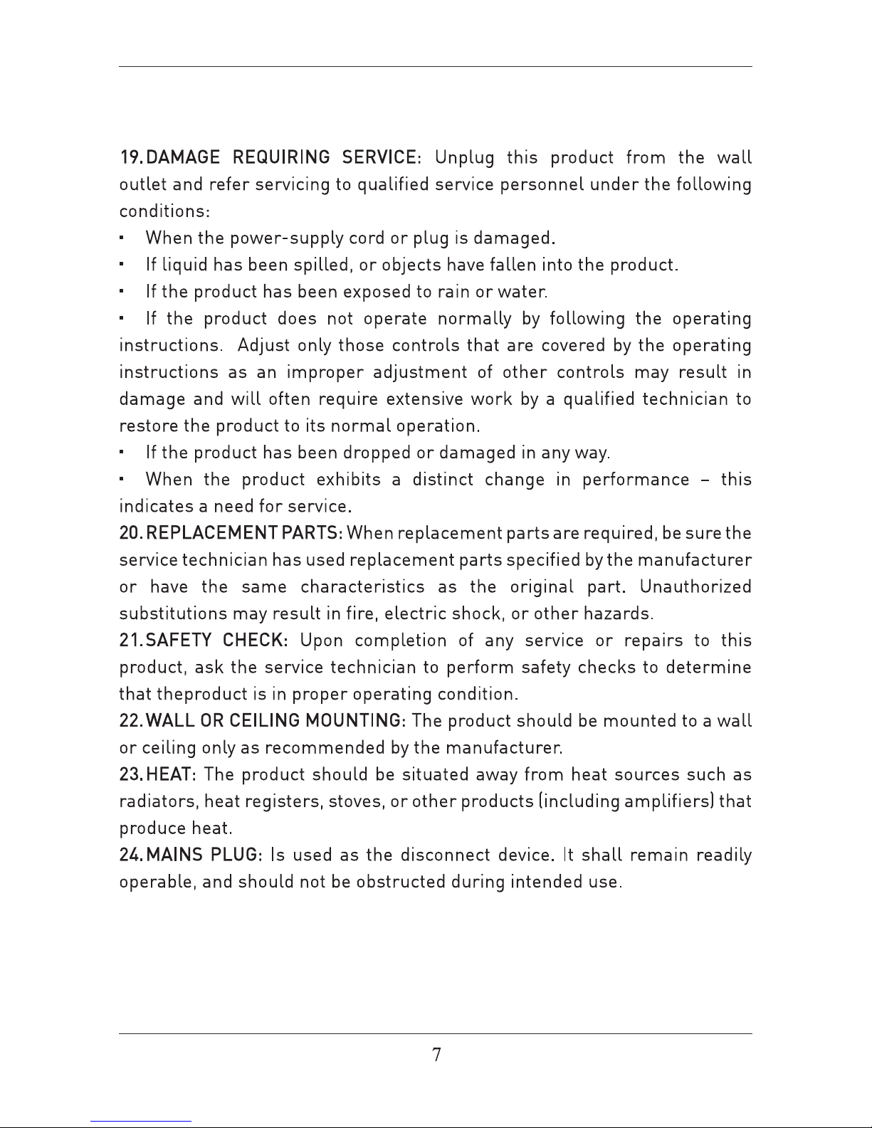
19
20
19
3.2. Audio/Video Source Selection
3.1. Initial Installation
3.3. DTV Mode Operations
SETTINGS
Initial Setup
4.1.Customizing the PICTURE Settings
4.2.Customizing the SOUND Settings
Page 4
31
32
34
PC Mode
4.3.Customizing theTIME Settings
4.4.Customizing the SETUP Settings
4.5.Customizing the LOCK Settings
4.6.Customizing the CHANNEL Settings
21
22
25
28
Page 5
Page 6
Page 7

Page 8
Page 9
Page 10
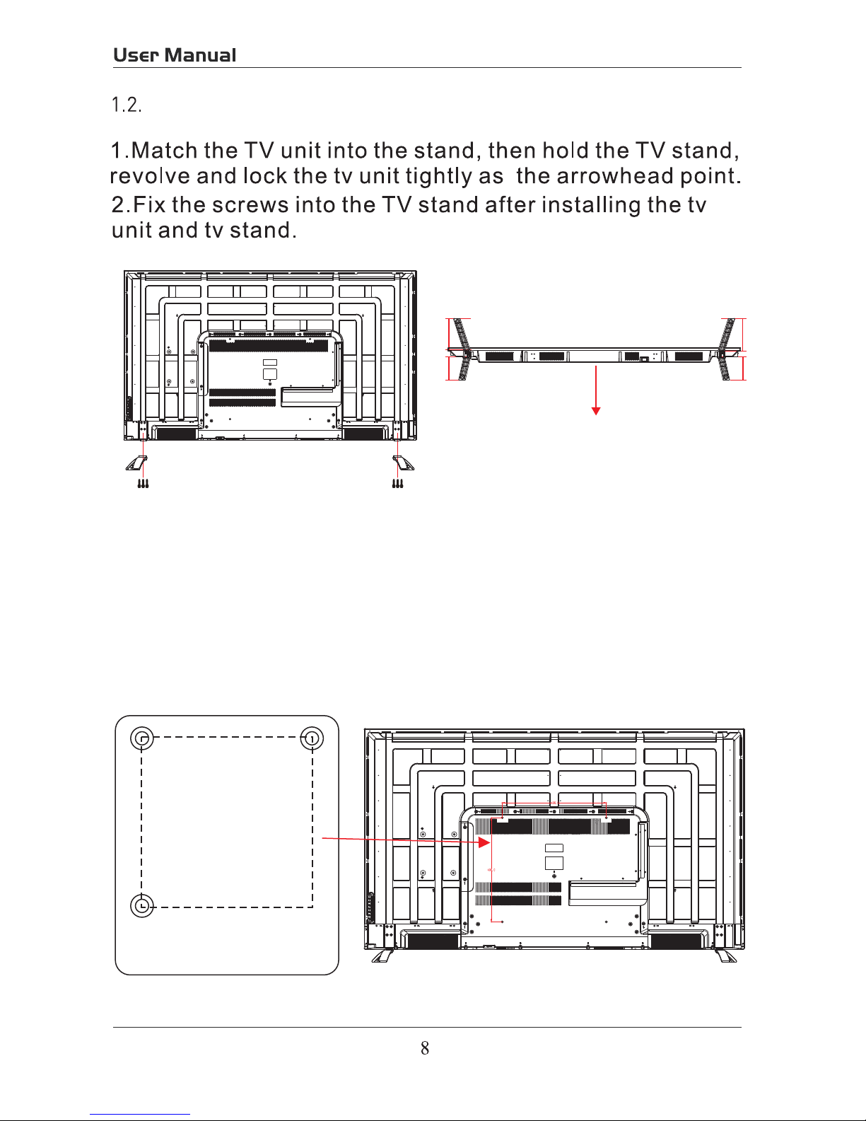
TV Base Stand assemble
3.Mounting on the wall
This unit is VESA-complian,and is designed to be wall-mounted
with a VESA-compliant 7.87"x7.87"(200mmx200mm)mounting kit
designde for flat-panel TVs(not supplied).Mount this unit according
to the instructions included in the monting kit. Length of screw should
not exceed 11mm
NOTE
Remove the base stand before mounting the unit on the wall.
Four mounting holes
(size M6 screw)
15.75”
15.75”
Panel side
Long Long
Short Short
R L
4*18BMH
Screws(3)
4*18BMH
Screws(3)
Page 11
Page 12

1. USB (For Service)
HDMI \ HDMI2 \ HDMI3
USB(For Service)
5V 0.5A
COAXIALR AUDIO L VIDEO/Y Pb Pr
PC AUDIOVGA RFHDMI3HDMI2HDMI1
Headphone
Page 13

Universal Remote Code:08F7
(Universal Rmote Control is not included)
ASPECT:Selects the screen size
sound from speakers
5.
Page 14
2
4
5
7
11
12
14
16
18
20
23
25
26
29
31
34
3
6
8
9
10
13
15
17
19
21
22
24
27
28
30
32
33
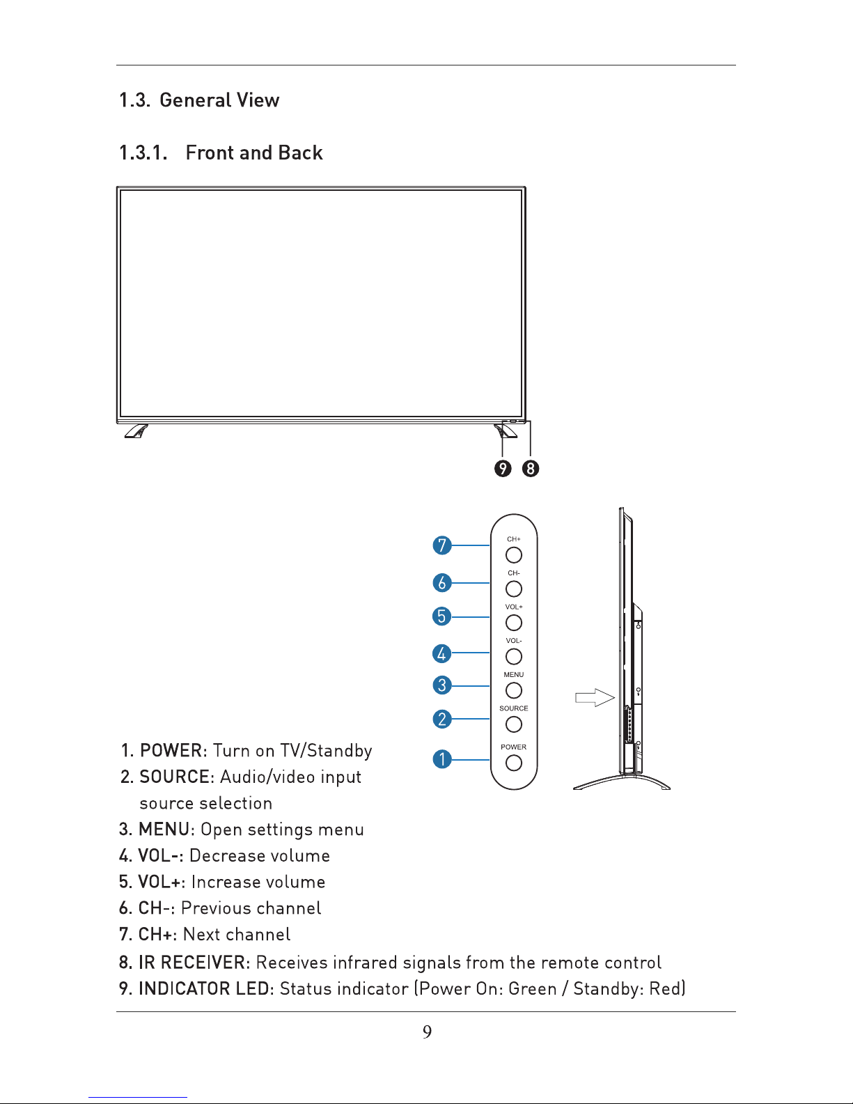
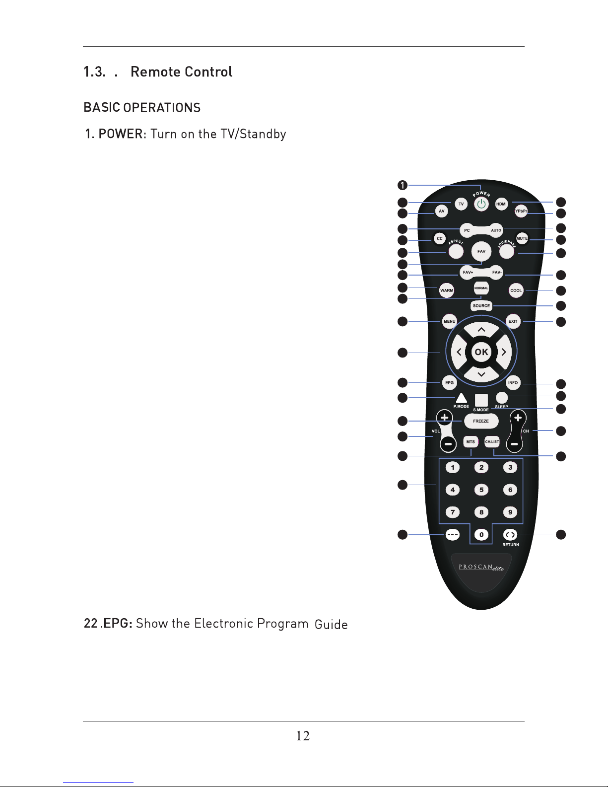
2. TV: Press to switch to TV signal source directly.
3. AV: Press to switch to AV signal source directly.
4. HDMI: Press to switch to HDMI signal source
directly.
5. YPbPr: Press to switch to YPbPr signal source
directly.
6. PC: Press to switch to VGA signal source directly.
7. AUTO: Press to adjust the picture automatically
in PC mode.
8. CC: CC mode.
9. ASPECT: Selects the screen size.
10. FAV: Show the list of favourite channels.
11. MUTE: Mute or restore the sound.
12. ADD/ERASE: Add/erase the favorite channels.
13. FAV+: Next favourite channel.
14. FAV-: Previous favourite channel.
15. WARM: The cool color temperature adjustment
16. COOL: To warm color temperature adjustment
17. NORMAL: To the standard color temperature
adjustment
18. SOURCE: Press to change signal source.
19. MENU: Show Menu.
20. EXIT: Exit the Menu.
23. INFO: Show information about the current program.
24.P.MODE: Output image mode selection.
25.SLEEP: Auto Power Off Timer.
26.S.MODE: Setting audio options.
21. NAVIGATION KEYS (Up, Down, Left,
Right and OK): To move in the menus and
confirm settings.
4
Page 15

27.FREEZE: Freeze the image.
28. VOL: Increase and decrease volume.
30. MTS: In the TV condition, press this button to
select the stereo mode.
29. CH: Next and Previous channel.
32. NUMBER KEYS: Change the channel directly.
33.
31. CH.LIST: Show the list of channels.
Page 16

adaptor
PC AUDIOVGA RFHDMI3
Page 17

USB
5V 0.5A
COAXIALR AUDIO L VIDEO/Y Pb Pr
USB
5V 0.5A
COAXIALR AUDIO L VIDEO/Y Pb Pr
Page 18

Note:Coaxial output
USB(For Service)
5V 0.5A
COAXIALR AUDIO L VIDEO/Y Pb Pr
PC AUDIOVGA RFHDMI3HDMI2HDMI1
Headphone
Page 19

PC AUDIOVGA RFHDMI3HDMI2
PC AUDIOVGA RFHDMI3HDMI2HDMI1
Headphone
17
Page 20

3.1. Initial Installation
The first time the unit is turned on or anytime the system is restored to
the defaulted settings, the Initial Installation wizard will be displayed on the
screen.
Conect the antenna cable to the RF connector at the connections panel
and follow the steps displayed on the screen to set up the system basic
settings (Language, Cable, etc.) and start an auto search of TV channels.
Turn on the TV by pressing the POWER button on TV
or on the remote control, press SOURCE and use the
direction buttons
/ to select the desired source
depending on the equipment you have connected (AV,
HDMI, PC) or choose TV to enter these mode.
Use MTS button to select the audio language broadcasting, CC button to
show or hide subtitles on screen and FAV button to see a list of your favorite
channels.
3.2. Audio/Video Source Selection
3.3. DTV Mode Operations
3. Initial Setup
4. SETTINGS
TV
AV
YPbPr
HDMI1
HDMI2
HDMI3
PC
Source Select
Use CH+ or CH- buttons to tune the desired channel, or enter the channel
number directly using the numeric keypad. Press OK to display on screen the
list of TV (press the
/ buttons to sort by group and show only the DTV,
the analog TV channels, etc.).
18
Page 21

Customizing the PICTURE
4.1.
Select TV source for example. (Press SOURCE bu on to select TV mode)
1. Press the POWER bu
on to turn the LED TV on.
2. Press the MENU bu
on on the remote control to display the Main menu, and use the ◄/►
to select the PICTURE.
3. Use the ▲/▼ bu
ons to highlight an individual PICTURE , use the ◄/► to
change the se
and press the MENU to exit the menu.
The PICTURE menu includes the following
:
Picture Mode
Contrast
Control the difference between the brightness and darkest regions of the
picture.
Brightness Control the overall brightness of the picture.
Color Control the color.
Tint Controls the
nt.
Sharpness
In
1)ASPECT RATIO This feature changes the various aspects of the TV’s video.
(Aspects include wide, zoom, cinema, normal).
contrast of the TV depending on the picture you are viewing.
crease this se
ng to see crisp edges in the picture; decrease it for so
edges.
Color
Advanced
Temp. Cycles among color modes: Normal, Cool. Warm,
Cycle among picture display modes: Standard, Dynamic,
19
Page 22

Customizing the SOUND
4.2.
Select TV source for example. (Press SOURCE bu on to select TV mode)
1. Press the POWER bu
on to turn the LED TV on.
2. Press the MENU bu
on on the remote control to display the Main menu, and use the ◄/►
to select the SOUND.
3. Use the ▲/▼ bu
ons to highlight an individual SOUND , use the ◄/► to
change the se
and press the MENU to exit the menu.
The SOUND menu includes the following op
ons:
MTS
AVL
Allow you to select among: Standard, Music, Movie, Sports and User.
Surround Allow you to select between Off and On.
from overly loud commercials.
This feature adjusts the second audio programming in analog channels.
Digital Audio
Output
Allow you to select between PCM, RAW and OFF.
Audio Language Allow you to select audio language among: English, French and Spanish.
20
Page 23

Customizing the TIME Se ngs
Select TV source for example. (Press SOURCE bu on to select TV mode)
1. Press the POWER bu
on to turn the LED TV on.
2. Press the MENU bu
on on the remote control to display the Main menu, and use the ◄/►
bu
ons to select the TIME.
3. Use the ▲/▼ bu
ons to highlight an individual TIME , use the ◄/► to
change the se
and press the MENU to exit.
The TIME menu includes the following op
ons:
Sleep
Time Format
Auto Clock
Clock
Timer
All
Please Note:
a power source. If the TV is unplugged or the power strip is turned off.
CABLE or SATELLITE of anything else please use make sure AUTO CLOCK
is turned off.
ow you to set up the sleep
among: 5min, 10min, 15min,
30min, 60min, 90min, 120min, 180min, 240min and off.
Time Zone
Allow you to set up the sleep
among: Pacific, Alaska, Hawaii,
East
Central and Mountain.
Daylight Saving Time Allow you to turn on or off the daylight saving
4.3.
21
Page 24

Select TV source for example. (Press SOUCE bu on to select TV mode)
1. Press the POWER bu
on to turn the LED TV on.
2. Press the MENU bu
on on the remote control to display the Main menu, and use the ◄/►
bu
ons to select the SETUP.
3. Use the ▲/▼ bu ons to highlight an individual SETUP , use the ◄/► to
change the se
and press the MENU to exit.
The SETUP menu includes the following op
ons:
Menu Language Allow you to select menu language among: English, Français and Español.
Transparent
OSD Timeout
Input PC signal first, then press SOURCE bu on to select PC mode, press ►
bu
on to confirm.
Customizing the SETUP Se ngs
4.4.
Input Label
images to show through.
22
Page 25

H-Posi on Allow you to use the ◄/► bu ons to adjust the H Posi on.
V-Posi on Allow you to use the ◄/► bu ons to adjust the V Posi on.
Clock Allow you to prolong the image.
Phase Allow you to adjust the de
Auto Select “Auto” and press the ► bu on, the unit will
automa adjust all items to achieve a best effect.
Close Cap on
Use the ▼ bu on to highlight the Close n item, then press the ►
bu on to enter into the following menu.
CC Mode Allow you to select the CC Mode among: On Off, and CC
on Mute.
Analog CC Allow you to select the basic sel on among: CC1, CC2,
CC3, CC4, Text1, Text2, Text3 and Text4.
Digital CC
Allow you to select the advanced sel on among:
Service1, Service2, Service3, Service4, Service 5 and
Service6.
Op Use the ▼ bu on to highlight the “Op on” item, then
press the ► bu on to enter into the following menu.
Exit
Exit
23
Page 26

Use the ▲/▼ bu ons to highlight the desired item, and
use the ◄/► bu
ons to select.
Restore Default Restore all se ngs in SETUP menu to factory se ngs.
Exit
Setup Wizard
Please Note:
Closed caponing is only available under AV and TV ports.
Closed caponing depends on your TV program’s support. Somemes due to the
TV channel or the signal, Closed caponing will not be available.
Exit
24
Page 27

Customizing the LOCK Se ngs
Select TV source for example. (Press SOURCE bu on to select TV mode)
1. Press the POWER bu
on to turn the LED TV on.
2. Press the MENU bu
on on the remote control to display the Main menu, and use the ◄/►
bu
ons to select the LOCK.
3. Use the ▼ bu
on to highlight “Enter Password” item, use the numeric keys to input 4-digital
password. A
er you that, the screen will display the junior menu. A er ngs, press menu
to exit.
NOTE: The factory password is 0000. The supervision password is 8899.
4-digital password
Input
The LOCK menu includes the following op
ons:
Change Password
Use the ▼ bu on to select the “Change Password” item, then press the
► bu
on to enter into the following menu.
Input the new 4-digital password and input it again to confirm.
System Lock
Allow you to turn on or off the system lock.
If you turn off the system lock, then the following items (US, Canada, RRT
Se ng and Reset RRT) will unable to use.
4.5.
Exit
2
25
Page 28

U
Use the ▼
►
enter into the following menu.
TV Use the ▼ bu on to highlight the “TV” item, then press
► bu on to enter into the following menu.
Use the ▲/▼ bu ons to select the desired ra ng and
press the ► bu on to block or unblock ra ng.
MPAA The Movie ra ng (MPAA) is used for original movies rated
by the Mo Picture Associa on (MPAA) as broadcasted
on cable TV and not edited for television.
Use the ▲/▼ bu ons to select N/A, G, PG, PG-13, R,
NC-17 or X.
RATING DESCRIPTION
G
General Audiences. Movie is appropriate for
all ages.
PG
Parental Guidance Suggested. May contain
material not suited for younger viewers
PG-13
Contains content that may not be
appropriate for viewers under the age of 13.
R
Restricted. Contains adult content, no one
under 17 admi d without parent.
NC-17 No one 17 and under admi
X Adults only.
Exit
Exit
226
Page 29

Canada
Use the ▼ ►
Canada English Use the ◄/► bu ons to select among: OFF, C, C8+, G,
PG, 14+ and 18+.
Canada French Use the ◄/► bu ons to select among: OFF, G, 8ans+,
13ans+, 16ans+ and 18ans+.
RRT Se
ng
Reset RRT Al
This feature is a downloadable rang filter based on TV broadcasts.
With the transion of TV broadcasts to digital, future changes, and
enhancements in how TV shows are rated for content are possible.
low you to reset the RRT se ng.
27
Page 30

Customizing the CHANNEL Se ngs
Select TV source for example. (Press SOUCE bu on to select TV mode)
1. Press the POWER bu
on to turn the LED TV on.
2. Press the MENU bu
on on the remote control to display the Main menu, and use the ◄/►
bu
ons to select the CHANNEL.
3. Use the ▲/▼ bu
ons to highlight an individual CHANNEL , use the ◄/► to
change the se
and press the MENU to exit.
The CHANNEL menu includes the following
:
Auto Scan
If you select “Air” as input signal in Antenna item, you can press the ►
bu on to search the channels automa cally.
4.6.
Use the▼ button to highlight the ”Auto Scan” item,then press ►
button to enter into the following menu.
Air/Cable
Allows you to select antenna between Air and Cable.
If you select “Cable”, the following items (Favorite, Channel List, Show/
Hide, Channel NO. and Channel Lable) are unable to use.
28
Page 31

The receivable channels will be stored automa cally.
When searching channels, press MENU to stop.
Use the ▼ bu
on to highlight the “Auto Scan”, then press the ►
bu
on to search the channels automa cally.
The receivable channels will be stored automa
cally.
When searching channels, press MENU to stop.
Favorite
Channel list
Allow you t add these channels which you desired as the favorite
channels. Use the ▲/▼ bu ons to highlight the “Favorite” item, then
press the ► bu on to enter into the following menu.
Use the ▲/▼ bu ons to highlight the desired item, then press OK
bu
on to add or remove the highlighted channel as favorite.
This feature shows the list of stored channels.
Show/Hide
Allow you to show or hide the channels.
Use the ▲/▼ bu ons to highlight the “Show/Hide” item, then press the
► bu on to enter into the following menu.
Exit
Exit
922
Page 32

Use the ▲/▼ bu ons to highlight the desired item, then press OK
bu on to show or hide the highlighted channel.
Channel No. Display the number of current channel.
Channel Label Display the lable of current channel.
Exit
Page 33

5. PC Mode
Se ng up your PC so ware (based on Windows XP)
The W indows display-se ngs for a typical computer are shown below. But the actual screen on
your PC will probably be different, depending upon your par
cular version of Windows and your
par cular video card. But even if your actual screen looks different, the same, basic set-up
informa on will apply in almost all cases.
1. First, click on “Control Panel” on the Windows start menu.
2. When the control panel window appears, click on “Appearance and Themes” and a display
dialog-box will appear.
3. When the control panel window appears, click on “Display” and a display dialog-box will
appear.
4. Navigate to the “Se
ng” tab on the display dialog-box. The correct size se ng (res
Op
1360×768.
If a ver
cal-frequency on exists on your display se ngs dialog box, the correct value is “60Hz”.
Otherwise, just click “Enter” and exit the dialog bo
x.
Res n
Horizontal
Frequency (KHz)
Frequency (Hz)
Standard Mode
720x400 31.47 70 DOS
640x480 37.9 60 VGA
800x600 37.9 60 SVGA
1024x768 48.4 60 XVGA
1366x768 64 60 SXVGA
1920x1080 64 60 SXVGA
Page 34

TV
TV
TV
6
Page 35

Page 36

and
EP6585
Audio output
350
5000:1
6.5
ms
1920x1080
220W
AC 100-120V~ 60Hz
HDMIx3
USB(For service)
7
7
 Loading...