

Page 1
USER MANUAL
P05
INTEGRATED MARKING PROGRAM
Ref. 92091 - P05_en_F - Last updated: 02/2008
Pro-Pen reserv es all rights to modify i ts products.
This document is non contractual.
www.pro-pen.com
Page 2
Table of conten ts
A - Introduction ................................................... ......... .... .... .... ........... .... .... .... ......... .... ........5
1. General characteristics of the program .................................................................................................. 5
2. Program fu n c ti on s . ... .. ............ ........... ........... ... ........... ............ ........... ............ ........... .. ............................5
Customization ...................................................................................................................................5
Type of blocks ...................................................................................................................................5
Functi ons within the bl o cks ........ ........... ............ ........... ........... ............ .. ............ ........... .....................5
Chara ct e r st y le s .. .. ............ ........... ........... ............ .. ............ ........... ............ ........... ........... . ..................6
Marking management .......................... .. .................. ............................... .. .. .................. ....................6
Adjustable settings ............................................................................................................................6
Various functions ...............................................................................................................................6
User memory .....................................................................................................................................7
Exchange of files via USB key ..........................................................................................................7
3. Charac te r e nc o d in g .................... ............ ........... ........... ... ........... ............ ........... ............ .........................7
Introduction .......................................................................................................................................7
UTF-8 encoding ................................................................................................................................7
Practical consequences ....................................................................................................................8
4. Startin g -u p th e pr ogram ........... ........... ............ .. ........... ............ ........... ............ .. ............ .......................10
5. The different program menus ...............................................................................................................10
Main menu .................. .................... ................. .. .. .. .. ................. .. .................... ................................10
6. Functi o ns o f th e ke ys u se d .. ............ ........... ............ ........... ........... ... ........... ............ ........... . ..................10
Functi ons with shor tc u ts . ............ ........... ............ ........... .. ............ ........... ............ ........... .. .................12
7. Use of gra p hi c ele me n ts ......... .. ........... ............ ........... ............ .. ........... ............ ........... ..........................12
8. Definition of a marking file ....................................................................................................................13
9. Creati n g a marking file ...... .. ............ ........... ............ .. ........... ............ ........... ............ .. ............................13
B - "Marking" menu ...........................................................................................................14
1. Marking "N times" ....... ............ ........... ........... ... ........... ............ ........... ............ .. ........... ..........................14
2. "Infini te " ma r ki n g ... ... ........... ............ ........... ............ ........... .. ............ ........... ............ ..............................16
3. "Independent" marking .........................................................................................................................17
C - "Edit file" menu ............................................................................................................18
Create a new marking file ...............................................................................................................18
Open the last file used ....................................................................................................................18
Open an e xi s tin g fil e ............ ........... ............ ........... ............ .. ........... ............ ........... ..........................19
1. Preparing a marking block ....................................................................................................................19
Block number ...... ........... ............ .. ........... ............ ........... ............ .. ............ ........... ........... .................20
File name ........................................................................................................................................20
Block name (label) ..... ........... ............ .. ........... ............ ........... ............ .. ........... ............ .....................20
Type of marking ..............................................................................................................................21
Text to be m a rk e d ............. .. ........... ............ ........... ............ ........... .. ............ ........... ............ ..............37
X-Y coordinates ...............................................................................................................................39
Chara ct e r si ze ....... .. ... ........... ............ ........... ........... ............ ........... ............ ........... ... .......................39
Text angl e ...... ............ ........... ............ ........... .. ............ ........... ............ ........... ............ .. .....................40
Marking force ..................................................................................................................................40
Character font ....... .. ............ ........... ... ........... ........... ............ ........... ............ .. ............ .......................40
Compre s sion ... ... ........... ............ ........... ............ ........... .. ............ ........... ............ ........... .. . ................41
Inclina tion .... ........... ............ ........... ............ ........... ............ ........... .. ............ ........... ..........................41
Spacing ..........................................................................................................................................41
Marking effects ...............................................................................................................................41
Alignme n t .. .. ........... ... ........... ............ ........... ........... ............ .. ............ ........... ............ .......................43
Marking direction ............................................................................................................................43
File speed option ........................... ................ .............................. .............................. ......................44
Marking speed ............. ............................................. ................ .......................................................44
Dot density per millimeter (electromagnetic version only) .................................... .. .............. ...........45
Ref. 92091 - P05_en_F
2/121
Page 3
2. "Edit" menu sub-menus ...................................... .. ................ ................ ................ ................................45
"Marking" sub-menu ........................................................................................................................46
"View" su b - m e n u ..................... ... ........... ............ ........... ........... ............ .. ............ ........... ...................47
"Edit" sub-menu ..............................................................................................................................54
"File" sub-menu ...............................................................................................................................56
Back to the previous menu ..............................................................................................................61
D - "Marking file management" menu ................................................................................62
1. Duplica te a fil e ... ........... ............ ........... ... ........... ........... ............ ........... ............ .. ...................................62
2. Renam e a file .. .. ........... ............ .. ............ ........... ........... ............ .. ............ ........... ...................................63
3. Delete a fi le ....... ........... ... ........... ............ ........... .. ............ ........... ............ .. ........... .................................63
4. Export a fi le ....... ........... ............ ........... ... ........... ........... ............ ........... ... ........... ...................................64
5. Import a fil e ............ ............ ........... ............ .. ............ ........... ........... ............ ........... ... . .............................65
E - "System info" menu ............. ..................................................... ...................................66
F - "File management" menu ............................................................................................. 68
1. Logo management ...............................................................................................................................68
Number of logo segments ........................ .......................................................................................69
Export a logo (LO3 format) ..............................................................................................................69
Re-index a logo ................ ........................................ ....................................... ................................70
Delete a logo ........................ .. .........................................................................................................70
Import a logo ...................................................................................................................................71
2. Font management ................................................................................................................................72
Font version ....................................................................................................................................73
Export a fon t (P O 3 fo r m a t) ......... .. .. ............ ........... ............ ........... .. ............ ........... ............ ..............73
Re-index a font ....................................................................... ....................................... ..................73
Delete a font .................................................................................................................................... 74
Import a font ....................................................................................................................................74
G - "Machine configuration" menu .....................................................................................7 6
1. Security m o d e ... .. ............ .. ........... ............ ........... ............ .. ........... ............ ........... .................................76
Password ........................................................................................................................................77
"Supervisor" mode ..........................................................................................................................77
"Operator" mode .............................................................................................................................78
2. Time and date settings ................ .. ................ ................ ................ .......................................................79
Time and date settings ....................................... ................ ................ ................ .. ...........................79
Setting th e clock .. ........... ............ .. ........... ............ ........... ............ .. ............ ........... ........... .................80
3. Display se ttings ................. ........... ............ .. ............ ........... ........... ............ ........... ... ..............................81
Contra s t . .. ............ ........... ............ ........... .. ............ ........... ............ ........... ............ .. ............................81
Screen rotated 180° ........................................................................................................................81
Display in reverse video .................................................. ....................................... .........................81
4. Machi n e pa ra m e te r s .......... ........... ............ ........... ............ ........... .. ............ ........... ............ . ....................82
Off-lim its control .. .. ............ ........... ........... ............ .. ............ ........... ............ ........... .. ..........................82
Convers io n o f th e un it s in to in c he s ............ ........... .. ............ ........... ............ .. ............ ........... ............84
End mark in g ty p e .. ............ ........... ........... ............ .. ............ ........... ............ ........... ........... .................84
5. Deleting a ll th e file s (re s e ting) .. ........... ............ .. ........... ............ ........... ... ........... ............ .......................86
6. Language .............................................................................................................................................87
7. Update ...... .. ........... ............ ........... ............ .. ............ ........... ........... ............ ........... ... . .............................87
Software update ............................................... ............................................... ................................88
Power firmware update .......... .. ....................................................................................... ................90
H - "Communication" menu ...............................................................................................92
1. Serial management ..............................................................................................................................92
Deactivate .......................................................................................................................................92
Raw data .................... ........... ............ .. ........... ............ ........... ............ ........... .. ............ .....................92
Comma n d instruction s ...... ........... ........... ............ .. ............ ........... ............ ........... .. ............ ..............92
Advanced command instructions ....................................................................................................93
2. Ethernet port management ...................................................................................................................93
Mode ...............................................................................................................................................94
Name of th e mac h in e ..... ... .. ........... ............ ........... ............ .. ........... ............ ........... ............ .. . ...........94
Ref. 92091 - P05_en_F
3/121
Page 4
3. USB port management .............................. ..................................................... ......................................94
4. Slave mode ..........................................................................................................................................94
I - "Variables" menu .................................. .... .. .. .... ..... .... .. .. .... .. .. ....... .. .... .. .. .... ..... .... .. .. .... ..95
1. Configu ring counte rs .. .. ............ .. ............ ........... ........... ............ .. ............ ........... ............ .......................95
Setting th e batc h nu mber ........... ........... .. ............ ........... ............ ........... ... ........... ........... .................97
Setting of the counter’s reset ..........................................................................................................98
2. Configu ring variable s ........... ............ ........... ............ .. ........... ............ ........... ............ .. ..........................100
Programming within a marking file ................................................................................................101
Compiling a series of variables .....................................................................................................101
3. Configu ring shifts . .. ............ .. ............ ........... ............ ........... .. ............ ........... ............ ............................102
Copying the contents of a day of the week ...................................................................................103
4. Configu ring Day/Mo n th / Y e a r fo rmat .. ........... ............ ........... ............ ........... ... ........... ........... ...............104
Year variable (YS) .........................................................................................................................104
Month variable (MS) ......................................................................................................................105
Day in the mo n th va riable (JS ) ... .. ........... ... ........... ............ ........... ............ ........... .. ............ ............105
Day of the w e e k varia b l e (DS ) ............ .. ............ ........... ........... ............ .. ............ ........... ............ .....106
Hour variable (HS) ........................................................................................................................107
J - Use .................................................................. ..................................................... ......109
1. Marking process flowchart ..................................................................................................................109
2. Initiati on to ma rking ...... ... .. ........... ............ ........... ... ........... ........... ............ .. ............ ............................110
Step 1: Sw it ch ing on the machine ....... .. ............ ........... ........... ... ........... ............ ........... ............ .. ...110
Step 2: Creating a marking file ......................................................................................................111
Step 3: Graphic preview before marking ....................... ................................................................117
Step 4: Po sitioning th e pl a te ...... .. ........... ............ ........... ............ ........... ... ........... ........... ...............117
Step 5: Adjusting the height of the stylus ......................................................................................117
Step 6: Ma rk ing simulation ......... ........... ............ ........... ........... ............ ........... ... ........... .................118
Step 7: Ma rk i ng th e pa r t .... .. ........... ............ ........... .. ............ ........... ............ ........... ............ ............119
K - Appendix .................................................................................................................... 121
Ref. 92091 - P05_en_F
4/121
Page 5
AIntroduction
This manual corresponds to the 2.10 version of the progr am.
Some screenshots may be different from those displayed in the
program.
1. General characteri stics of the pro gr am
The P05 standard marking progra m is inte grat ed in a Contr ol Unit, or i n the main board of t he machine (v iewed on
an LCD screen). It is used to:
• program files for marki ng:
- set text
- variable text:
. dates (using various set or customized formats)
. counters (incrementation, decrementation)
- logos
A
2. Program functions
Customization
• multilingual: prog ram language selection
• "Supervisor" mode / "Operato r" mode (access rights to certain functions or entry fields for text or coordinates)
• units (c m or inches )
Type of block
• marking:
- linear (choice of the angle)
- radial
• logos
• pilots a rot ating third axis (DP3500/DP4500) for marking on circular parts
Functions within the blocks
• delay between blocks (DELAY)
• marking of simple geometric shapes:
- circles
- lines
Ref. 9209 1 - P05_en_F
5/121
Page 6

Character styles
• marking effects:
- normal
- inverted
- mirror
- reflected
• alignment
• compression / expansion
• inclination
• spacing between characters
Marking management
• standard marking:
- marking N par ts
- infinite ma rking
• independent marking
Adjustable settings
AIntroduction
A
• customized speeds for marking and movement
• force (depth)
• date and time (CCU clock)
• variables:
- 10 numeric counters which can be reset each time there is a change in year, month, day, time, shift
- 10 alphanumeric variables
- shift codes (Q) set according to the day of the week (up to 5 shifts per day)
- date and time based on CCU system, using the keywords:
. DD - MM - YYYY - YY - Y - hh - mm - ss - WW - CCC
. m (mark first digit of the minutes)
. customized formats DS (day/week), JS (day/month), MS (month) et YS (year)
• choose a character font
Various functions
• display available memory
• download logos (LO3 - PLT format)
• transfer marking files between PC and the machine (Backup / Restore)
• simulate marking file (no marking on part)
• off-limits management
• set time for changing "day of the year" (CCC) code
• date and time display
• change orientati on of screen display
• standard international font
Ref. 92091 - P05_en_F
6/121
Page 7

AIntroduction
User memory
Available memory is 512 kB.
Several hundred files may be saved, depen ding on their size.
Maximum:
• 100 blocks per file
• 255 characters per block
Exchange of files via USB key
It is possible to import and export ce rtain files via USB key (FAT32 file system only):
• marking file
• logos
• character font
Files must be located in the root directory of t he file tree structure on the USB key. Do not place them in
directories.
A
3. Character encoding
Introduction
The previous marking progr ams us ed "8 bi t" f ont s, which c oul d only cont ai n 2 8 = 256 characters. The font change
was necessary for each language, display and marking were impossible for languages including over 256
characters.
16
Marking and display fonts used in the P05 program are "16 bit" programs, which may contain up to 2
characters (less in practical terms, cer tain are reserved). These fonts are based on t he setup of the characters of
the ISO/IEC 10646 standard, in the Basic Multilingual Plan. This standard, which specifies a set of universal
characters (Univer sal Char acter Se t) , als o defin es other char acters (o ver 1.1 mill ion). These are not gener ated by
the P05 program and must therefore not be used.
The 16 bit font s are used to manage new languages and increase compatibility with the actual operatin g systems
(Window s , Un ix . ..) . H o w e ver, nume ro u s mat er ia ls a nd a pplications st ill u s e 8 bit fo nts . In ord e r to ha v e the b es t
possible compatibil ity with th ese materi als, t he charact ers emitted and received by the progr am (files or charac ter
strings) are encoded in UTF-8 (UCS Transformation Format, 8 bits). UTF-8 is used to represent the 16 bit
characters by using 8 bit codes. This font does not allow old 8 bit systems to manage 16 bit characters, but it
allows to manipulate the acceptabl e data and to transmit them with no loss of information.
UTF-8 encoding
UTF-8 was designed to be compatible with specific software initially foreseen for the processing of one-byte
characters. Each 16 bit character is encoded on a chain of 1 to 4 bytes.
= 65536
UTF-8 is normalised in the RFC-3629 (UTF-8, a transformation format of ISO 10646). Encoding is also defi ned in
the 17 technical report of the Unicode standard. It is part of the standard on Chapter 3 "Compliance" and is
approved by the Internationa l Standard Org aniz ation (ISO) , the Int ernet Enginee ri ng Task Force (IETF) as well as
most of the national standardization organizations.
Ref. 92091 - P05_en_F
7/121
Page 8
AIntroduction
Encoding
The numbered characters from 0 to 127 are encoded on 1 byte(s) whose most significant bit is always 0.
The characters with a number greater than 127 are encoded over several bytes. I n this case, the most signif icant
bits of the first byte form a series of 1 as long as the number of byt es used to encode the character, the following
bytes having 10 as the most significant bit.
Definition of the number of bytes used
UTF-8 binary representation Meaning
0xxxxxxx 1 byte coding 1 to 7 bits (from 0 to 127)
110xxxxx 10xxxxxx 2 bytes coding 8 to 11 bits (from 128 to 2047)
1110xxxx 10xxxxxx 10xxxxxx 3 bytes coding 12 to 16 bits (from 2048 to 65535)
11110xxx 10xxxxxx 10xxxxxx 10xxxxxx 4 bytes coding 17 to 21 bits (from 65536 to 2097151)
This idea could be applied up to 6 bytes but UTF-8 set s the limit to 4. This idea also allows the use of more bytes
than needed to code a character but the UTF-8 forbids it .
Note: The UTF-8 representation over 4 bytes corresponds to a character code greater than 65535, which
must not be used with the P05 program.
A
Example:
Example of the UTF-8 encoding
Character Character number UTF-8 binary encoding
A65 01000001
é 233 11000011 10101001
8364 11100010 10000010 10101100
In any UTF-8 character string, any 0 most significant bit byte encodes a US-ASCII character on a byte. The
characters whose codes are included between 0 and 127 are therefore represented the same way as in ASCII
(non-accentuated, capital and small letters, numbers and some frequent initials).
Practical consequences
The old systems using the ASCII 8 bit fonts may communicate with the P05 program, which uses 16 bit fonts. To
allow this interoperability, 2 methods are possible:
• The ASCII and UCS tables are common for the characters numbered from 0 to 127. For t hese characters, compatibility i s guaranteed.
• For other characters, UTF-8 encodi ng is used to specify the 16 bit character code by using th e sequences of
several 8 bit "characters", which can be managed by 8 bit systems.
Using the P05 program
As long as the program doesn’t exchange data with the exterior, it uses the 16 native bit fonts. The user can
benefit from extended linguistic support.
Ref. 92091 - P05_en_F
8/121
Page 9

AIntroduction
Manual editing of the marking files
The marking files (.tml files) in TML format (Technifor Marking Language) are saved in UTF-8 format. This f ormat
is automatically recogni zed when a f ile is opene d wi th Note Pad (not ep ad.exe) in Win dows ( 2000 or more rece nt).
For an exact display, select a compatible display font, such as "Arial Unicode MS".
When saving, make sure the UTF-8 format is well selected (especially when creating a new file).
Data reception/emiss ion (RS232, telnet)
The characters received must be encoded in UTF-8. Characters emitted are encoded in UTF-8.
If a device sends to the machine characters in ASCII enc oding, they are only recognized if their codes are
included between 0 and 127. In this manner, this device may corr ectly receive the characters whose codes are
included between 0 and 127.
To use other characters, these must be encoded in UTF-8.
For example: To send the "é" character, the device cannot use the ASCII encoding of the Latin 1 character page
which assigns this character the code 130.
It must use UCS encoding which assigns it the code 133. In UTF-8, the code is written as follows:
11000011 10101001
It must thus send 2 bytes: 195 - 169
A
DataMatrix
This format only allows the encoding of character strings of 8 bits. The internal strings of the program are thus
converted in UTF-8 before being encoded in Dat aMatrix, which enables encoding of all 16 bit characters to be
managed. The size of the DataMatri x needed for this enco ding is gr eater t han 8 bit char acter en codi ng as several
8 bit characters are needed to carry out UTF-8 encoding of a 16 bit character.
When the encoded characters have ASCI I or UCS co des between 0 and 127 , Dat aMatrix encoding is made i n the
classic way and the size of the DataMatr ix generated is the same.
Unicode
Unicode is an international sta ndard which defines a set of universal character s, as i n the ISO/ IEC 10646
standard. The Unicode charac ter codes correspond to those in the ISO/IEC 10646 standard and the Uni code
standard includes the ISO/IEC 10646 completely as a sub-set.
The Unicode standard adds to the ISO/IEC 10646 standard a representation model and complete word
processing, by assigning to each character a set of standardized or informative properties and by accurately
describing the semantic relations which may exist between several succes sive characters of a text. It also
standardizes the processing algorithms which preserve semantics of transformed texts to a maximum, while
spreading interoperabi lity of the representati on of these texts on heterogeneous systems.
This allows, for example, to specify the meaning of a text, so that two characters may be associated and for m
one, etc...
Unicode management is complex and is not currently implemented in the P05 program. In the future, certain
Unicode rules will be added to the softwar e, therefore allowing a parti al support of Unicode according to needs.
Ref. 92091 - P05_en_F
9/121
Page 10
AIntroduction
4. Starting-up the program
Check that the power cable is connected.
Turning on the CCU or the machine will launch the marking prog ram.
A presentation screen will appear for a few seconds, followed by the main menu screen.
Turn off the machine before any intervention.
5. The different program menus
A
Main menu
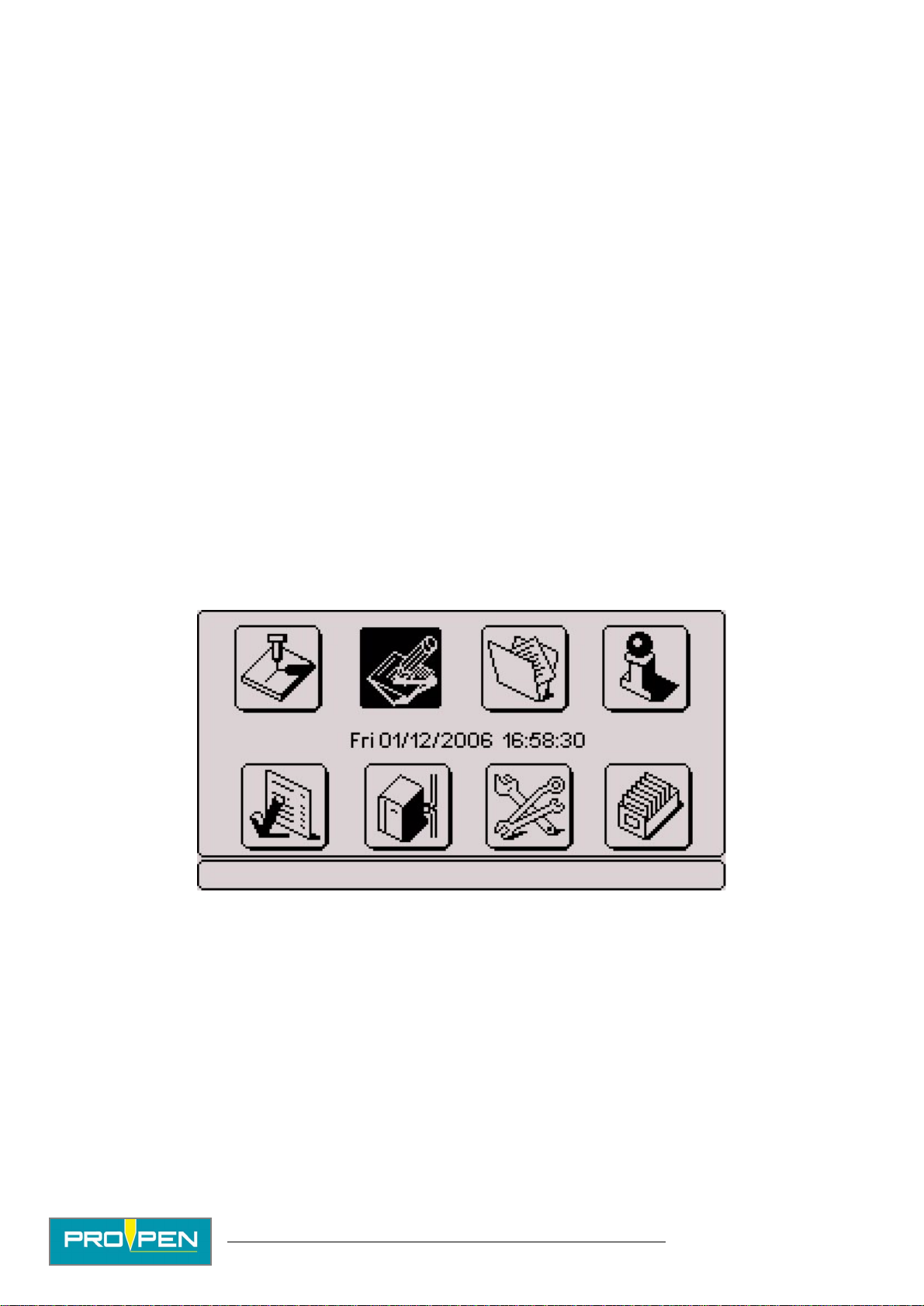
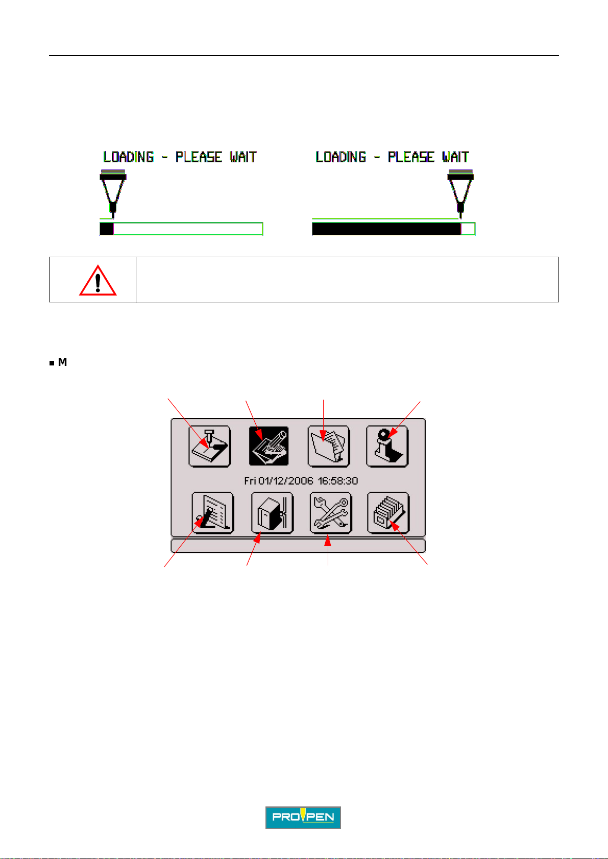
The main menu is composed of 8 menus, each represented by an icon.
12 3
8
1 : "Marking" menu
2 : "Edit file" menu
3 : "Marking file management" menu
4 : "System info" menu
5 : "File management" menu
6 : "Machine configuration" menu
7 : "Communication" menu
8 : "Variables" menu
4
567
6. Functions of t he keys used
The keyboard is used to access the different menus and program functions and to enter the information needed
for markin g .
Use the Tab key or the Left - Right arr ows to se lect t he d esired menu. The negati ve image of the sel ected i con will
appear . Validate by pressing Enter .
Ref. 92091 - P05_en_F
10/121
Page 11
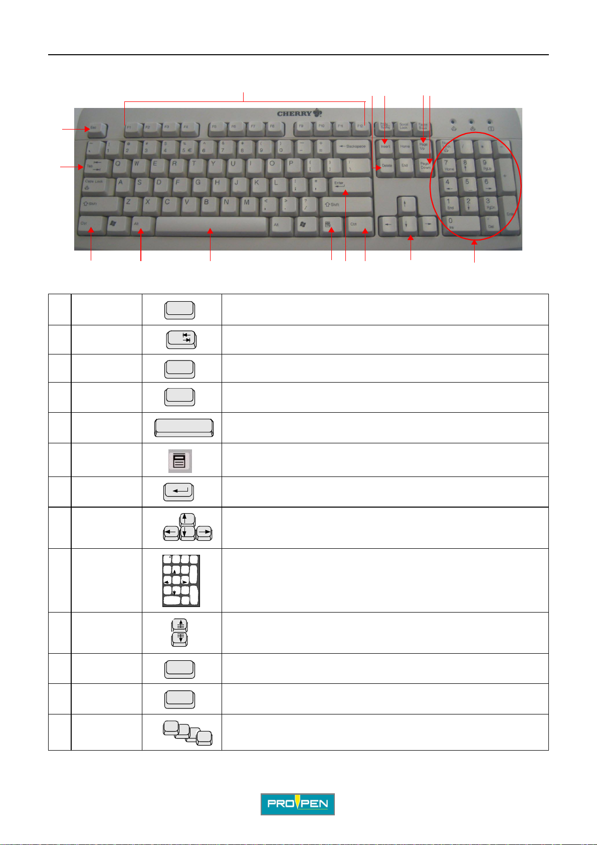
The keys most often used are:
1
2
AIntroduction
A
111213
10
1 Escape Return to previous screen
Esc
7
653 34 9
8
2 Tab Access to various menus or tabs used to prepare a block
3 Ctrl Access to certain shortcuts using the keyboard
4 Alt Access to certain shortcuts using the keyboard
Ctrl
Alt
5 Space Activation / deactivation of the blocks, multi-selection of files to import/export
6 Context menu Gives acces to the sub-menu bar in the "Edit file" menu, return to "Edit" mode,
travel from one part of the screen to the other within certain menus
7 Enter Validation of the entered data, modifying a data entry zone, activation / deacti-
vation of the radio button
8 Up - Down -
Left - Right
Move the cursor to different data entry areassetting the stylus position in the
"Stylus movement" function (F3)
arrows
_
Num
9 Numeric
keypad
/
*
Lock
789
PgUp
Home
456
123
End
PgDn
.
0
Ins Del
Entering numeric values, incrementation / decrementation of numeric values
+
Enter
with the +/- keys, setting the stylus position in the "Stylus movement" function
(F3)
10 Page Up -
Page Down
Travel from one block to another during editing, setting the initial angle on the
rotary device in the (F3) function "Stylus movement", skipping pages in some
menus
1 1 Insert Insertion of an empty block in a marki ng file be fore the sel ected block, insert io n
12 Delete Deletion of a block from a marking file
13 Function keys S hortcuts to some functions in the program
Ref. 92091 - P05_en_F
Insert
Delete
F1
of a key word in the "Text" field
F12
11/121
Page 12
AIntroduction
Functions with shortcuts
Certain functions can be obtained using a keyboard shortcut:
• Ctrl + Alt + I: display in reverse video - See page(s) 81
• Ctrl + Alt + F: screen rotated 180° - See page(s) 81
• Ctrl + Alt + A/Q: more or less contrast on the screen - See page(s) 81
• Ctrl + Alt + R: exit slave mode - See page(s) 94
• Ctrl + P: pause after a bl ock - See page(s) 47
• Insert: insertion of an empty block in a marking file before the select ed block - See page(s) 54
• Delete: deletion of a block from a marking file - See page(s) 55
• F2: marking preview - See page(s) 49
• F3: stylus movement - See page(s) 52
• F4: simulation of the current block - See page(s) 47
• F5: add a block at the end of the file - See page(s) 54
• F7: copy a block - See page(s) 55
• F8: view 1/3/5 blocks - See page(s) 48 - 49
• F9: simulate marking file (no marki ng on part) - See page(s) 47
• F10: file marked - See page(s) 46
• F11: save selected fi le - See page(s) 56
• F12: properties of the file - See page(s) 57
A
7. Use of graphic elements
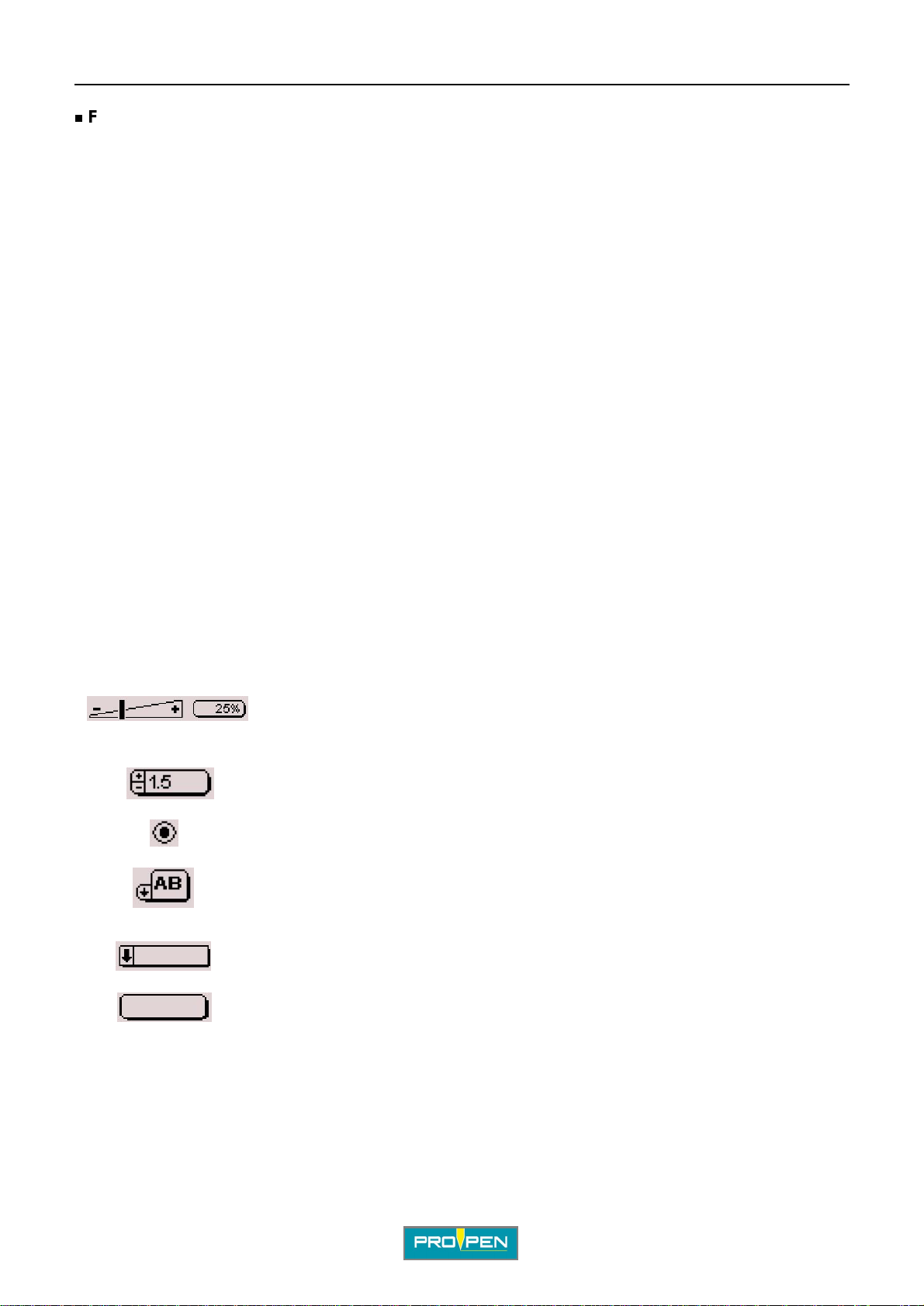
Certain elements concerning graphic data are fo und at several points in the program. The entry mode for each is
as follows:
Incrementation / dec rement ation of t he percent ag e using t he +/- k eys on the numer ic keypad
Incrementation / decr eme ntation of the values using the +/- keys on the numeric
keypad or by manually typing them after pressing the Enter key
Radio button: activation / deactivation usi ng the Enter key. It is possible to select just
one at a time
Scrolldown icon menu. Press Enter to scrol ldown, then on the Up - Down arrows of
the keyboard to navigate.
Scrolldown text menu. Press Enter to scrol ldown, then on the Up - Down arrows of the
keyboard to navigate.
Open text e n try fie ld. Press En te r to m o v e to th is fie ld .
Ref. 92091 - P05_en_F
12/121
Page 13
AIntroduction
8. Definit io n of a m a rking file
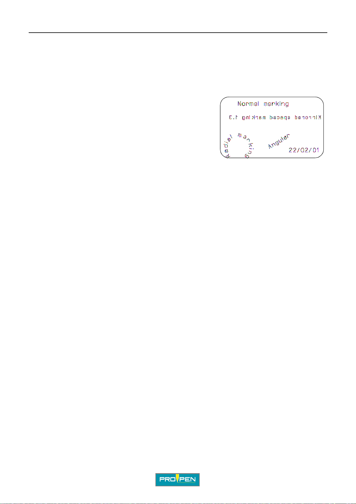
A marking file contains all the data to be marked on a part.
It may be composed of one or several lines.
In Pro-Pen jargon, a marking file is composed of marking blocks.
A marking block may contain alphanumeric text, a logo, a line, a
square...
A marking file can contain anywhere from 1 to 100 marking blocks.
The marking file used to create this plate contains 5 marking blocks.
The following pages describe the preparation of various types of
marking blocks.
9. Creating a marking file
To create a new marking file, use the arr ows to sel ect the "Edit file". Validate by pressing Enter.
A
Select the "Create a new file" icon. Validate by pressing Enter.
An empty block will appear. Press Enter to enter data. See: "Preparing a marking block".
Ref. 92091 - P05_en_F
13/121
Page 14
B"Marking" menu
Select this menu from the main menu, represented by the icon:
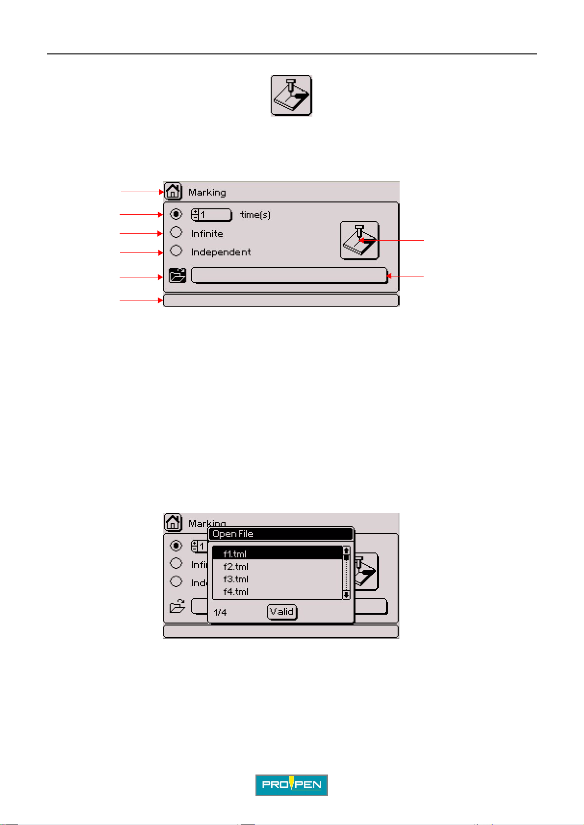
The screen below appears:
1
2
B
3
7
4
5
8
6
1 : Icon used to return to the main menu, followed by the name of the menu. This icon appears several times in the program.
2 : Marking "N times"
3 : "Infinite" marking
4 : "Independent" marking
5 : Open file.
6 : Pop-up help associated with the current function. This field is always present.
7 : "Start marking" icon
8 : Name of the file to be opened
1. Marking "N times"
Used to mark the same marking file a set number of times
Select the number of markings requested. The default value is 1.
Use the arrows to select the "Open" icon. Validate by pressing Enter. Choose the file to be marked. Validate by
pressing Enter.
Ref. 9209 1 - P05_en_F
14/121
Page 15
A"Marking" menu
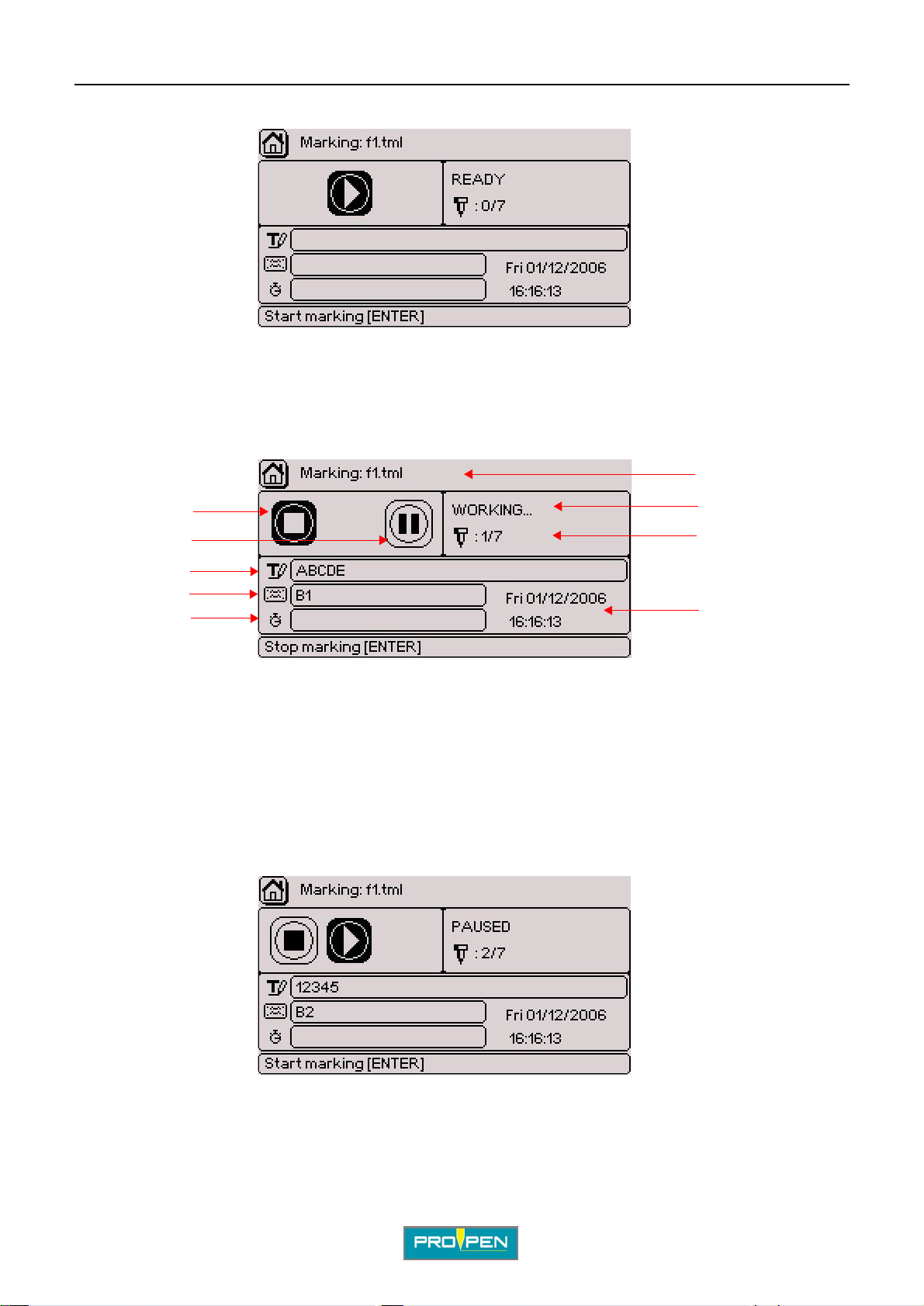
Move to the "Start marking" icon. Validate by pres sing Enter . The scr een below appears:
This screen provides information concerning the file to be marked and the stat us of t he marki ng. The cursor is
positioned on the "S tart marking" icon. Validate by pressing Enter.
Note: Triggering the marking can be also carried out by closing the "Start marking" contact present on the
appropriate connector of the machine. For more information, consult the manual of the machine in question.
During marking, the screen below appe ars:
6
B
1
2
7
8
3
4
5
1 : "Stop marking" icon
2 : "Pause during marking" icon
3 : Text for the block being marked
4 : Name of the block being marked
5 : Marking time. Appears once the markings are completed.
6 : Name of the file being marked
7 : Status of marking
8 : Number of markings carried out in relation to the total number of markings to be done
9 : Current time and date
To paus e marking, place the cursor on the co rresponding icon. Validate by pressing Enter. Marking is interrupted.
The screen below appears:
9
The cursor is located on the "Restart marking" icon. To restart marking, press Enter.
To stop marking, place the cursor on the "Stop marking" icon. Validate by pressing Enter. Marking is stopped.
Ref. 92091 - P05_en_F
15/121
Page 16
A"Marking" menu
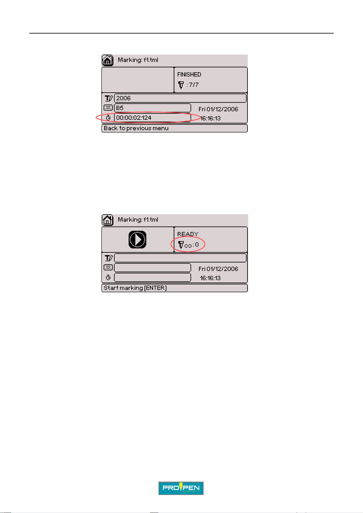
At the end of the marking, the screen indicates the marki ng ti me .
2. "Inf inite" ma rking
It is a marking mode similar to "N times" except that the marking is repeated i nfi nitely.
Select the file to be opened using the up/down key s To access the "Infinite" option, use the Up - Down arr o ws on
the keyboard. Validate by pressing Enter.
B
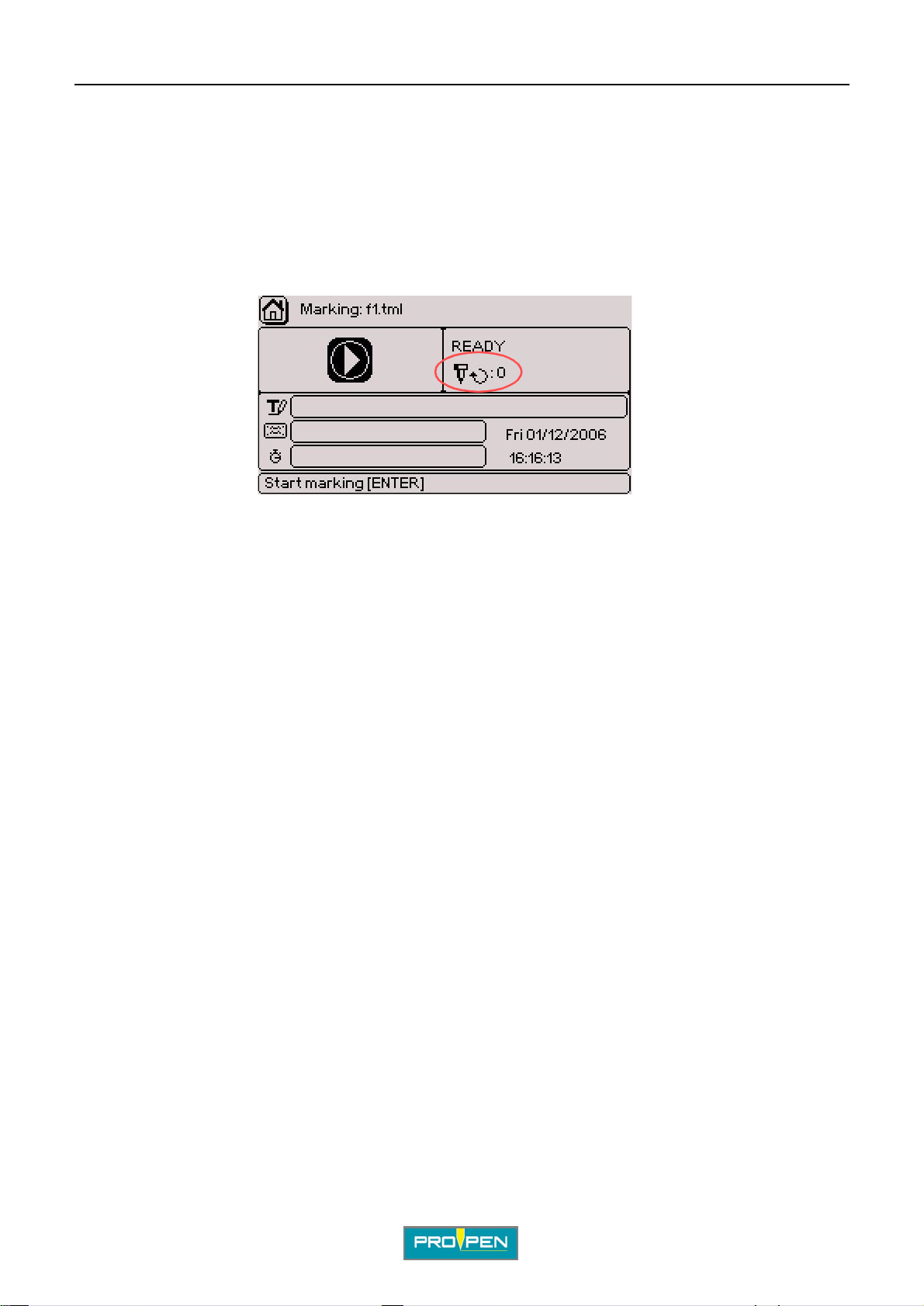
Move to the "Start marking" icon. Validate by pres sing Enter . The scr een below appears:
The "Infinite" symbol appears next to the number of markings carried out.
Once one marking is completed, press Enter to launch the next marking.
To pause marking or stop the marking in progress: See: "Marking "N times" ".
Ref. 92091 - P05_en_F
16/121
Page 17
A"Marking" menu
3. "Independent" marking
Used to obtain markings identical t o those i n "Inf inite" mode, the only difference being that when the machine is
switched back on after an interruption during marking (reset, power outage...) marking is resumed by clicking on
"St art marking". The keyboard doesn’t have to be connected to resume marking.
Select the file to be opened using the up/down keys To access the "Independent" option, use the Up - Down
arrows on the keyboard. Val idate by pressing Enter.
Move to the "Start marking" icon. Validate by pres sing Enter . The scr een below appears:
B
The "Independent" symbol appears next to the number of marki ngs carried out.
Once one marking is completed, press Enter to launch the next marking.
To pause marking or stop the marking in progress: See: "Marking "N times" ".
Ref. 92091 - P05_en_F
17/121
Page 18
C"Edit file" menu
Select this menu from the main menu, represented by the icon:
The screen below appears:
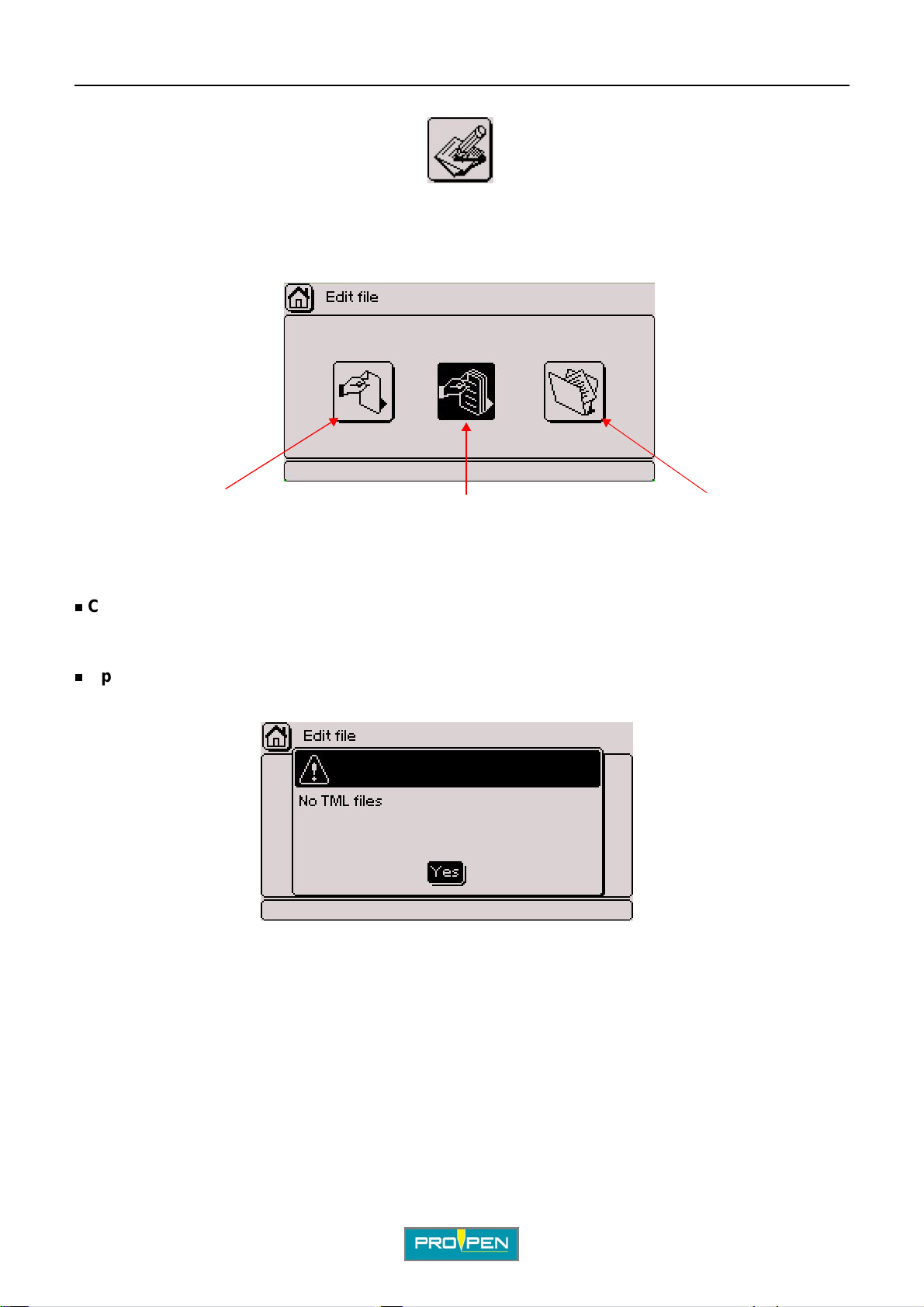
123
C
1 : Create a new marking file
2 : Open the last file used
3 : Open an existing file
Create a new marking file
Gives access to an "empty" marking file to prepare marking blocks. See: "Prep aring a marking block".
Open the last file used
Used to directly open the last file used. If there is no file in memory, the following message appears:
Go to "Create a new file" to prepare blocks for a new fi le.
Ref. 9209 1 - P05_en_F
18/121
Page 19
A"Edit file" menu
Open an existing file
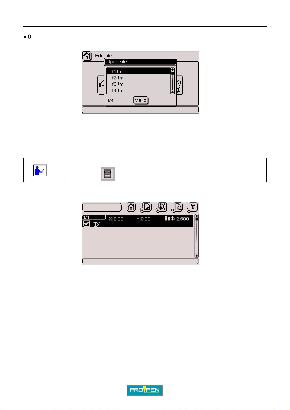
Used to open a specific file. The screen below appears:
Choose the file to be opened using the Up - Down arrows. Validate by pressi ng Enter.
1. Preparing a marking block
C
To access the sub-menu bar at the top of the screen, press the Context menu key on
the keyboard. See: ""Edit" menu sub-menus"
When a file is created, an empty block appears on the sc reen.
Ref. 92091 - P05_en_F
19/121
Page 20
A"Edit file" menu
TAB 1:
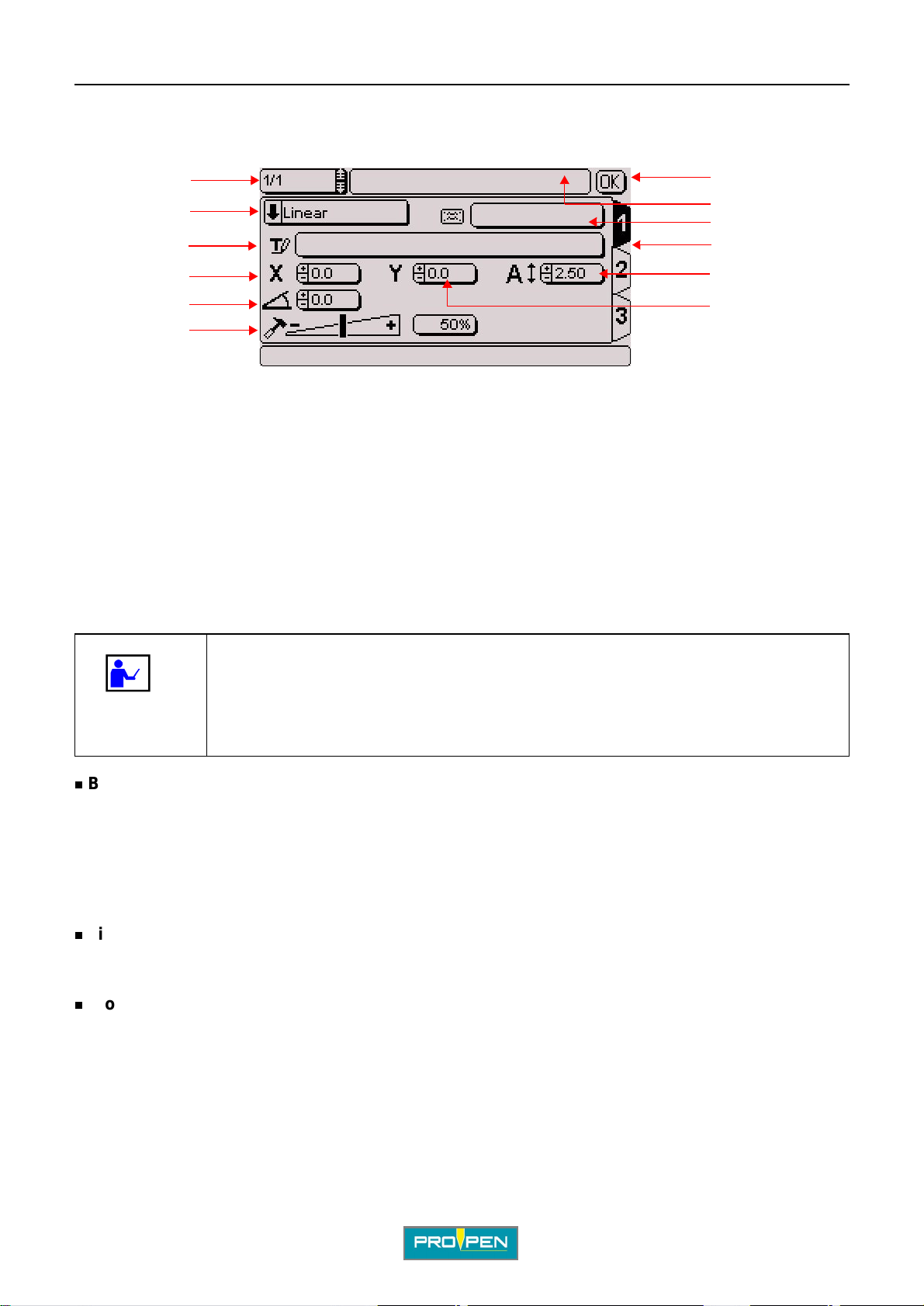
Press Enter to prepare the block. The first data entry screen appears (tab 1).
C
1
2
3
4
5
6
1 : Block number
2 : Type of marking
3 : Text to be marked
4 : X coordinate
5 : Text angle
6 : Marking force
7 : Save block and return to previous screen
8 : File name
9 : Block name (label)
10 : Number of the data entry screen (tab)
11 : Character size
12 : Y coordinate
7
8
9
10
11
12
At any time during the preparation of a block:
• Press the Page Up - Page Down arrows on the keyboard to move from one block to
another in a marking file. The cursor appears on the same data entry block as the
one for the block in progress except that it’s the next block.
• Press the Tab key to move from one tab to another within the same block.
Block number
Each block is identified by a number. This number evolves automat ically when blocks are added or deleted.
The first number indicates the number of the selected bl ock. The second number corresponds to the total
number of blocks in the file.
Press the Page Up - Page Down arrows on the keyboard to move from one block to another in a marking file.
File name
The name of the file appears in this filed if it has been saved. While preparing a new file, this field is empty.
Block name (label)
Used to name each marking block. This optional, free access data entry field can be used to add information
about the block or instructions for the operator which will be diplayed during the marking of the block in question.
Ref. 92091 - P05_en_F
20/121
Page 21
A"Edit file" menu
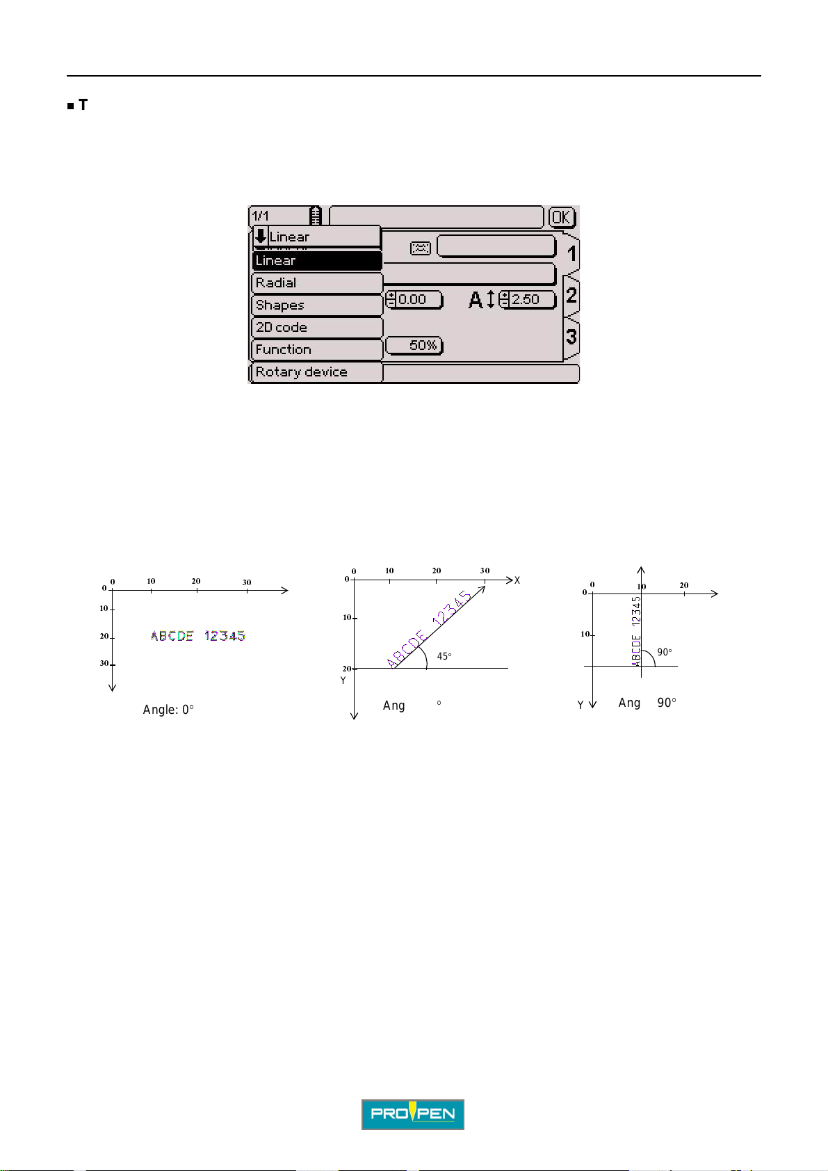
Type of marking
This field defines the type of marking to be carried out in the block being prepared.
Certain types of marking invol ve new data entry fields.
To access this data entry field, use the arrows on the keyboard. Validate by pressing Enter. The screen below
appears:
Select the desired type of marking using the Up - Down arrows. Linear marking is selected by default.
Linear marking
C
Used to mark straight lines of text at an angle.
To obtain a marking parallel to the X axis, set the angle at 0° in the corresponding (5) field.
To obtain a marking parallel to the Y axis, set the angle at 90°.
10
0
10
0
0
10
20
30
20
30
X
Y
Angle: 0
°
0
10
20
Y
Angle: 45
20
45
°
30
X
°
0
0
10
Y
10
90
Angle: 90
20
X
°
°
Ref. 92091 - P05_en_F
21/121
Page 22
A"Edit file" menu
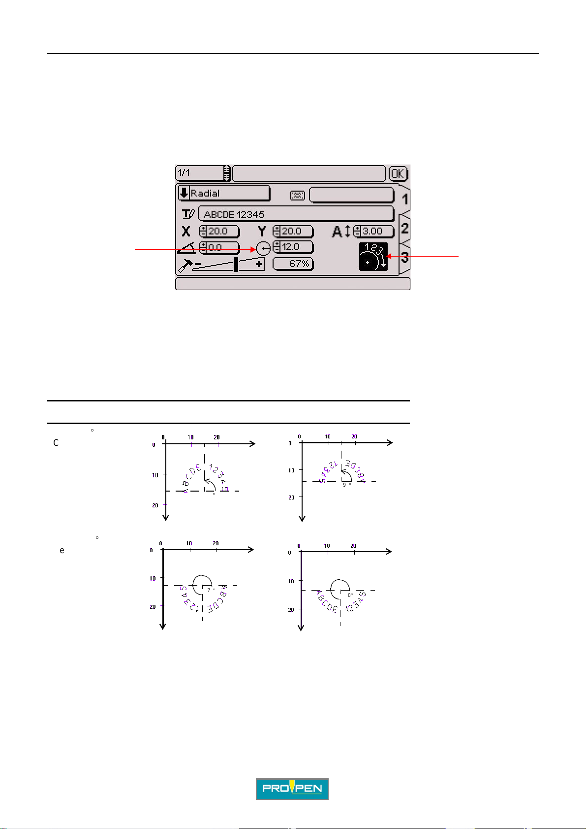
Radial marking
Used to obtain t exts along th e circumference of a circle. When this type of marking is selected, a new field (1) for
entering the circle radius value appears on the screen.
The angle value in degrees corresponds to the positioning angle of the marking on the circle.
The X-Y coordinates correspond to the center of the base circle for the marking.
A new icon (2), used to choose the marking direction, appears at the bottom right side of the screen.
C
1
2
1 : "R adius" field
2 : Marking direction icon
Clockwise marking / counter-clockwise marking
In radial marking mode, select the marking direction icon with the arrows in order to select clockwise or counterclockwise marking. Clockwise marking is selected by default.
Initial angle Clockwise marking Counter-clockwise marking
Angle: 90
Centering
°
X
90
°
90
°
Y
Y
X
Angle: 270
°
Centering
Ref. 92091 - P05_en_F
X
270
°
Y
Y
270
°
X
22/121
Page 23
A"Edit file" menu
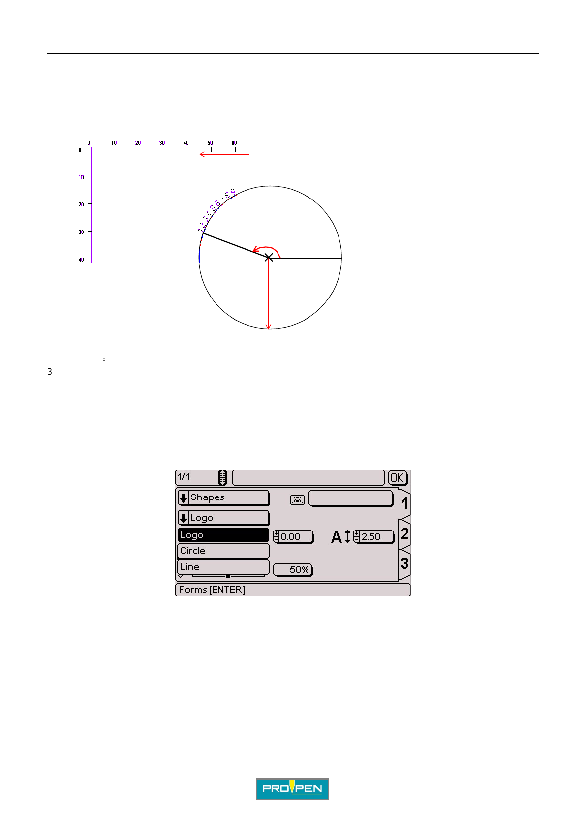
Special situation
It is possible tha t the c enter o f the c ircl e is l ocated out side the ma rking z one. I n this case, t he X and Y coordina tes
are superior or inferior to the marking area. Check that the text to be marked is within the marking area.
Example of a circle outside the marking area:
1
2
3
C
1 : Marking area: 60 mm (2.362 in) x 40 mm (1.575 in)
2 : Angle: 160
3 : Radius: 50 mm (1.969 in)
Shapes (pneumatic version only)
Used to mark logos, lines, circles...
When the "Shapes" type of marking is selected, choose the desired type of shape. Position the cursor on the
"Types of shapes" field. Press Enter to access the entry field. The screen below appears:
Select the type of shape using the Up - Down arrows. Validate by pressing Enter.
°
Ref. 92091 - P05_en_F
23/121
Page 24
A"Edit file" menu
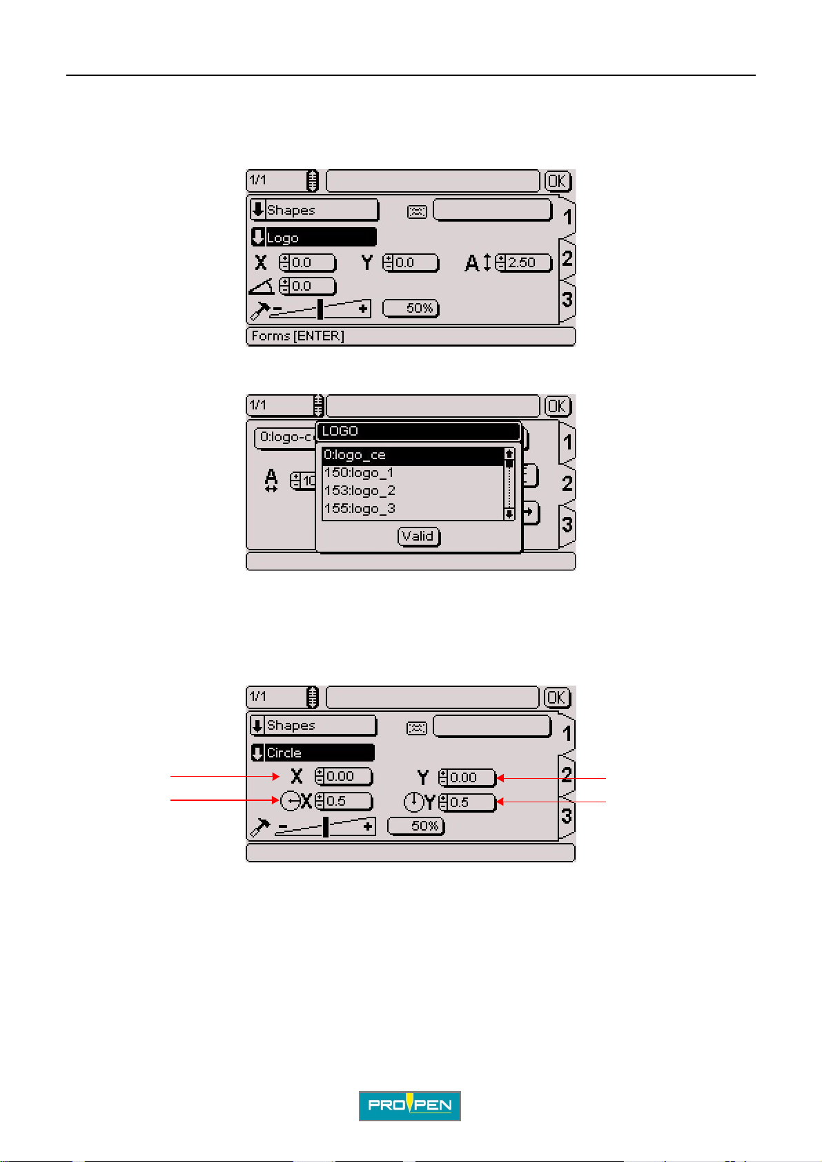
• Logos
Used to mark the logos saved in the CCU.
The screen below appears:
To select the logo to be marked, go to tab 2. Position the cursor on the "Logo" field. Press Enter to access the
entry field. The screen below appears:
C
Select the logo using the Up - Down arrows. Validate by pressing Enter.
• Circles
Used to mark circles, ellipses, circle arcs.
The screen below appears:
1
2
1 : X coordinate
2 : Radius in X
3 : Y coordinate
4 : Radius in Y
Select the circle’s radius in X and Y.
To trace a circle, the radius in X and Y values must be identical.
To trace an ellipse, the radius in X and Y values must be different.
3
4
Vert ical ellipse: radius i n X < radiu s in Y Horizontal ellipse: radius in X > radius in Y
Ref. 92091 - P05_en_F
24/121
Page 25
A"Edit file" menu
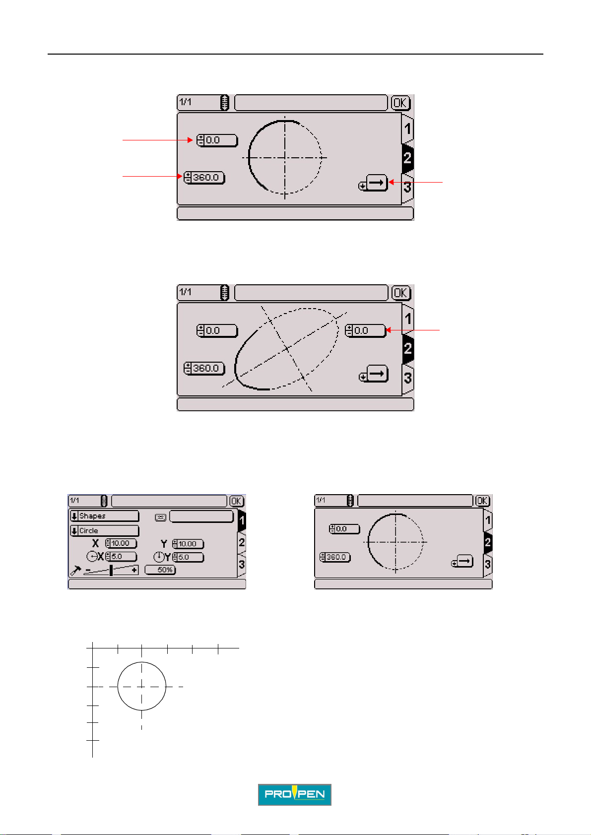
Once all these fields a re fi lled, use the keyboard’s Tab key or arrows to switch to t ab 2 in order to pro ceed wi th the
preparation of the block. The screen below appears:
1
C
2
1 : Initial angle (degrees)
2 : End angle (degrees)
3 : Marking direction
To mark an ellipse, an additional field appears on the screen.
4 : Inclination (angle in degrees)
Sample ins t ru c tio n s fo r obta in in g a c ir cl e:
3
4
Marking obtained:
0
5
10
15
Y
5
T AB 1: T AB 2:
15
10
X
X = 10 mm Y = 10 mm Radius in X = 5 mm Radius in Y = 5 mm
Ref. 92091 - P05_en_F
25/121
Page 26
A"Edit file" menu
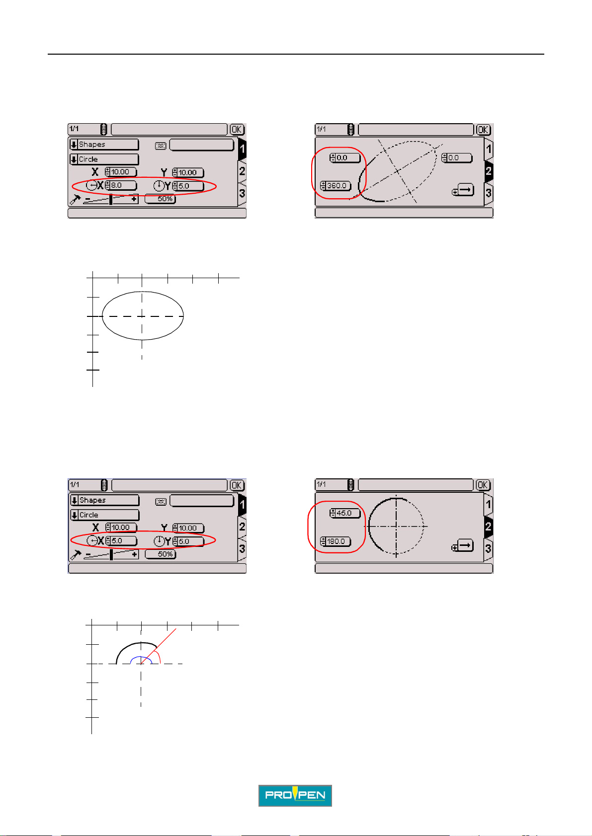
Sample instructions for obtaining a horizontal oval:
T AB 1: T AB 2:
Marking obtained:
C
0
5
10
15
Y
Sample instructions for obtaining a curved line:
5
15
10
T AB 1: T AB 2:
X
X = 10 mm Y = 10 mm Radius in X = 8 mm Radius in Y = 5 mm
Marking obtained:
0
5
10
15
Y
Ref. 92091 - P05_en_F
5
180°
10
15
45°
X
X = 10 mm
Y = 10 mm
Radius in X = 5 mm
Radius in Y = 5 mm
Initial angle: 45°
End angle: 180°
26/121
Page 27
A"Edit file" menu
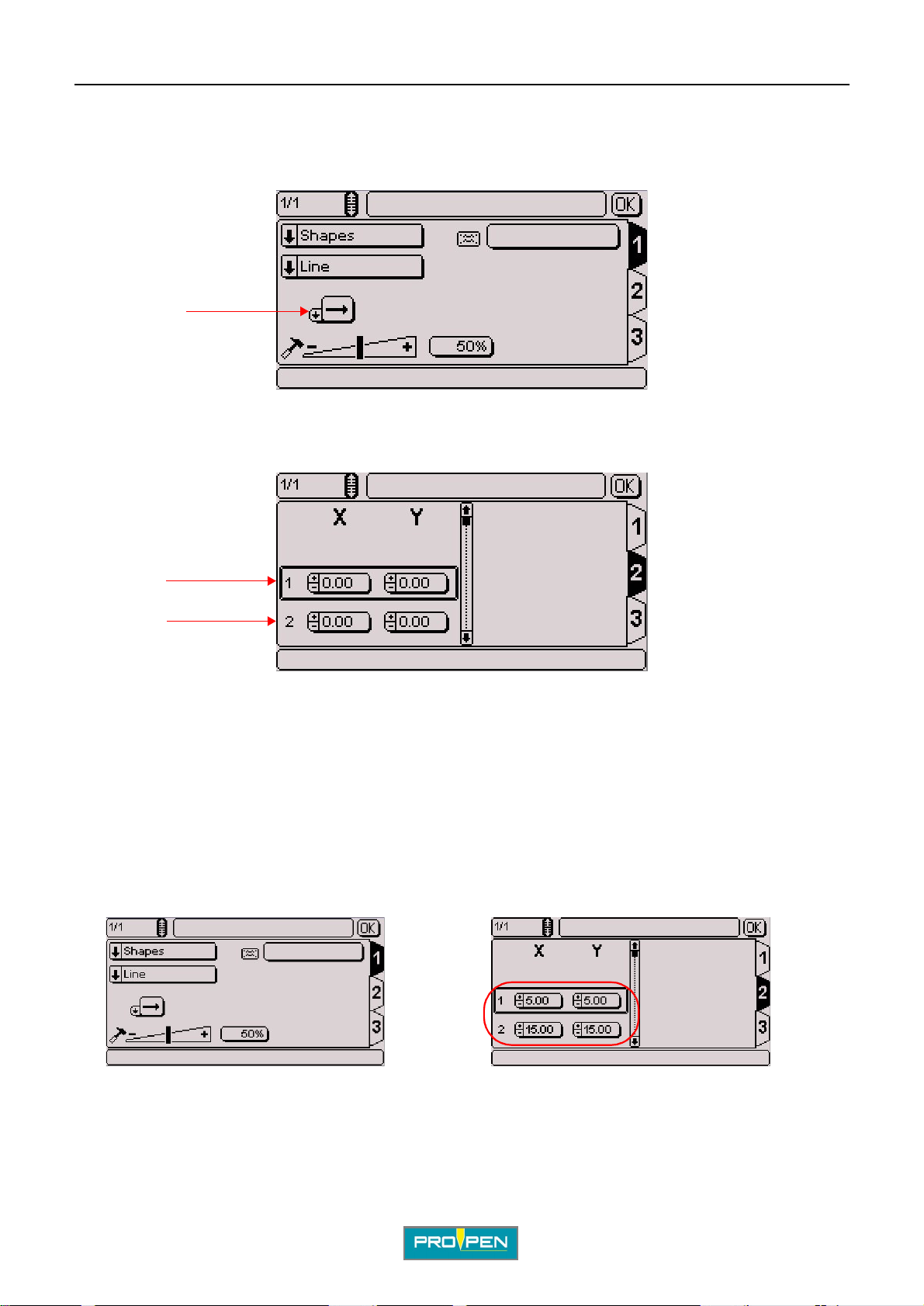
• Lines
Used to mark one or several lines.
The screen below appears:
1
1 : Marking direction
Once all these fields a re fi lled, use the keyboard’s Tab key or arrows to switch to t ab 2 in order to pro ceed wi th the
preparation of the block. The screen below appears:
C
2
3
2 : X-Y coordinates of point 1.
3 : X-Y coordinates of point 2.
It is possible to choose up to 16 points to establish one or several lines.
To insert a point below the sel ected point, press the Insert key on the keyboard.
To add a point at the end of the list, pre ss the F5 key on the keyboard.
To delete a point, press the Delete key on the keyboard.
Sample instructions for obtaining a slanted line:
T AB 1: T AB 2:
Ref. 92091 - P05_en_F
27/121
Page 28
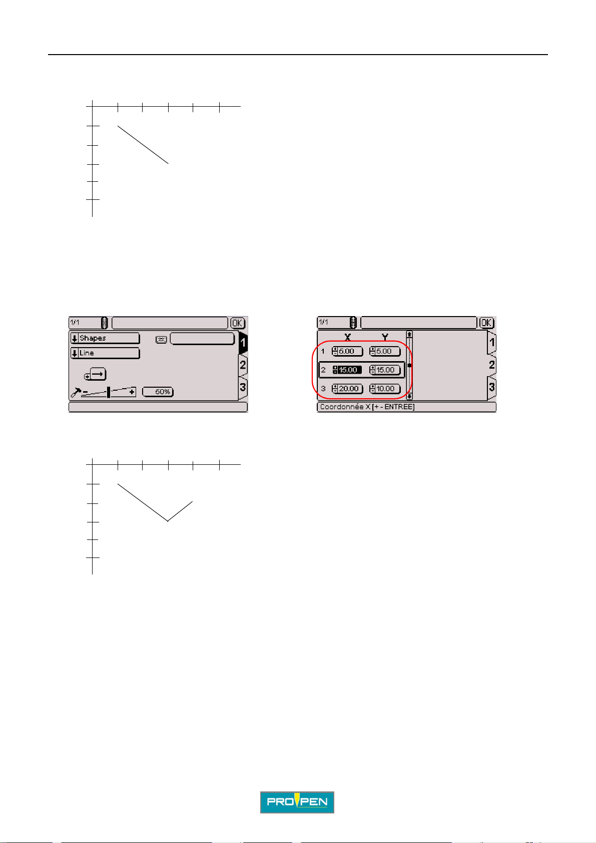
Marking obtained:
A"Edit file" menu
C
0
5
10
15
Y
Sample instructions for obtaining a series of lines:
5
15
10
T AB 1: T AB 2:
X
Marking obtained:
0
5
10
15
Y
5
10
15
20
X
Ref. 92091 - P05_en_F
28/121
Page 29
A"Edit file" menu
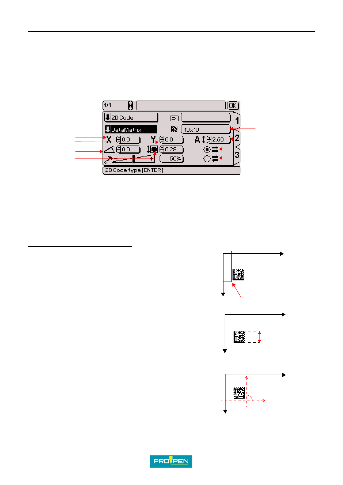
2D code (optional)
Used to mark DataMatrix codes.
When the "2D code" marking type is selected, choose the desired type of code. Position the cursor on the "Code
types" field. Press Enter to acces s the ent ry field.
• DataMatrix
The screen below appears:
4
C
1
2
3
1 : X-Y coordinates
2 : Angle in degrees
3 : Cell size
4 : Matrix format
5 : Size of the DataMatrix code (height)
6 : One way marking
7 : Return marking
Position and size of the DataMatrix code :
X-Y coordinates: The values entered in the X and Y fields
determine the start position of the DataMatrix marking.
1 : The X represents the start marking point (X-Y coordinates).
Size: The value entered in this field defin es the hei ght of the
DataMatrix code. This value automatically adapts itself according
to the size of the cells and the matrix format.
50
Y
5
6
7
10
0
X
1
0
X
X
1 : Size of the DataMatrix code
Angle: The value entered in this field defin es the angl e in degr ees
along which the DataMatrix code is marked.
1 : Angle in degrees
Ref. 92091 - P05_en_F
1
Y
0
1
Y
X
29/121
Page 30
A"Edit file" menu
Note
To maintain a high marking quality, the angle value must be a multiple of 90° (0°, 90°, 180°, 270°).
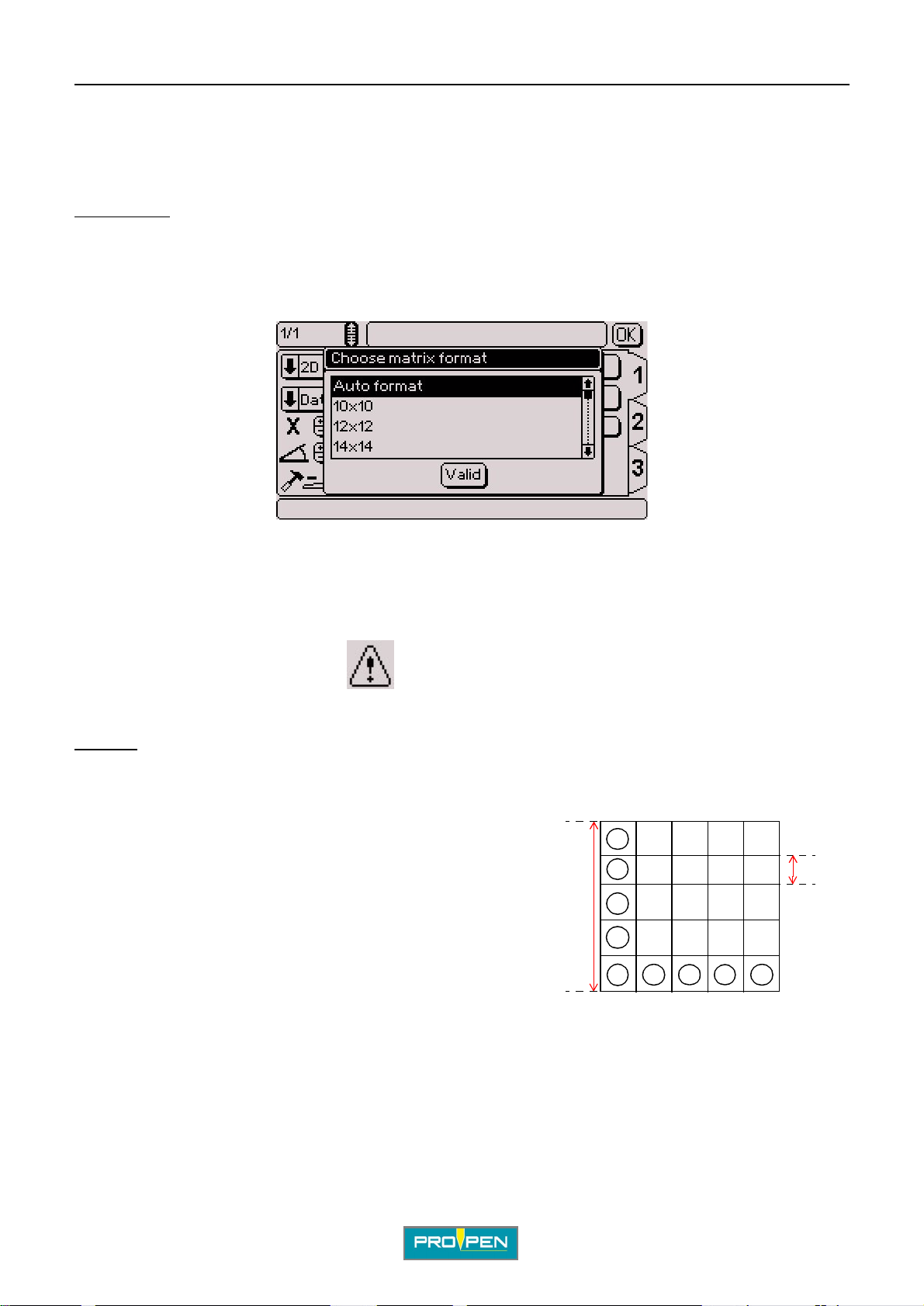
Matrix format:
Defines the number of lines and columns contai ned in th e DataMatrix code. Several pre-defined formats are
available.
Position the cursor on the "Matrix format" using the arrows. Validate by pressing Enter. The screen below
appears:
C
Select the desired matrix format using the arrows. Validate by pressing Enter.
Choose "Auto" format to have the program ca lculate automatically the number of lines and columns necessary to
encode the text to be marked.
When the matrix format selected does not allow the representat ion of the text to mark, a warning symbol appears
in the lower right corner of the screen.
Cell size:
To know the height of the cells which make up the code, divide the size of the code by the number of lines in the
format selected.
Example 1:
Size of the DataMatrix code: 10 mm (0.394 in)
Matrix format: 20 x 20
=> cell size: 10 mm (0.394 in)/20 = 0.5 mm (0.02 in)
Example 2: If:
- cell = 0.67 mm (0.026 in)
- format: 20*20
Size of the DataMatrix code: 0.67 mm (0.026 in) x 20 = 13.4 mm (0.528 in)
1
1 : Size of the DataMatrix code
2 : Height of a cell in the DataMatrix code
2
The size of the cells automatically adapts it self accordi ng to the size of the DataMatrix code and the matrix format.
Ref. 92091 - P05_en_F
30/121
Page 31
A"Edit file" menu
One way marking / return marking:
One way marking: The stylus always restar ts from the left at the beginning of each line. It favors the regularity o f
marking ahead of the speed.
Return marking: The styl us marks t he fir st l ine of the c ode f rom lef t to ri ght, then the sec ond fr om ri ght t o lef t, etc ...
It favors the marking speed.
Select one box or the other. Validate by pressing Enter.
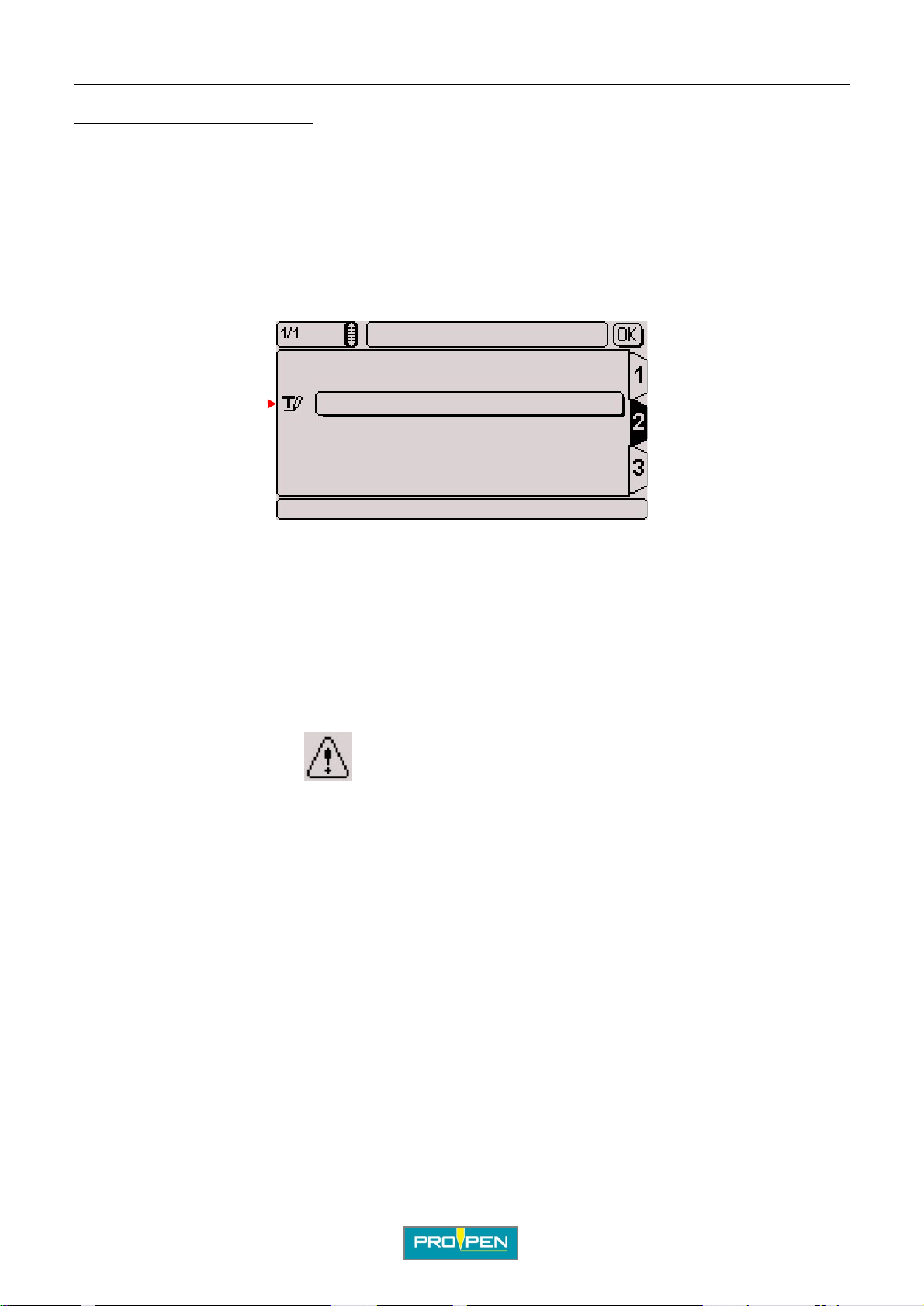
To enter other information specific to DataMatrix, go to tab 2 . The screen below appears:
1
C
1 : Text to be marked
Text to be marked:
Insert the text to be encoded in DataMatri x.
The processing of non-printable 04 - 29 - 30 characters is authori zed (U_ID). To insert them, use the
corresponding ASCII codes.
In the event of missing or too long text in relat ion to the size of the code sel ected, a warning symbol appears in the
lower right corner of the screen.
Ref. 92091 - P05_en_F
31/121
Page 32
A"Edit file" menu
Function
Gives access to certain automated functions.
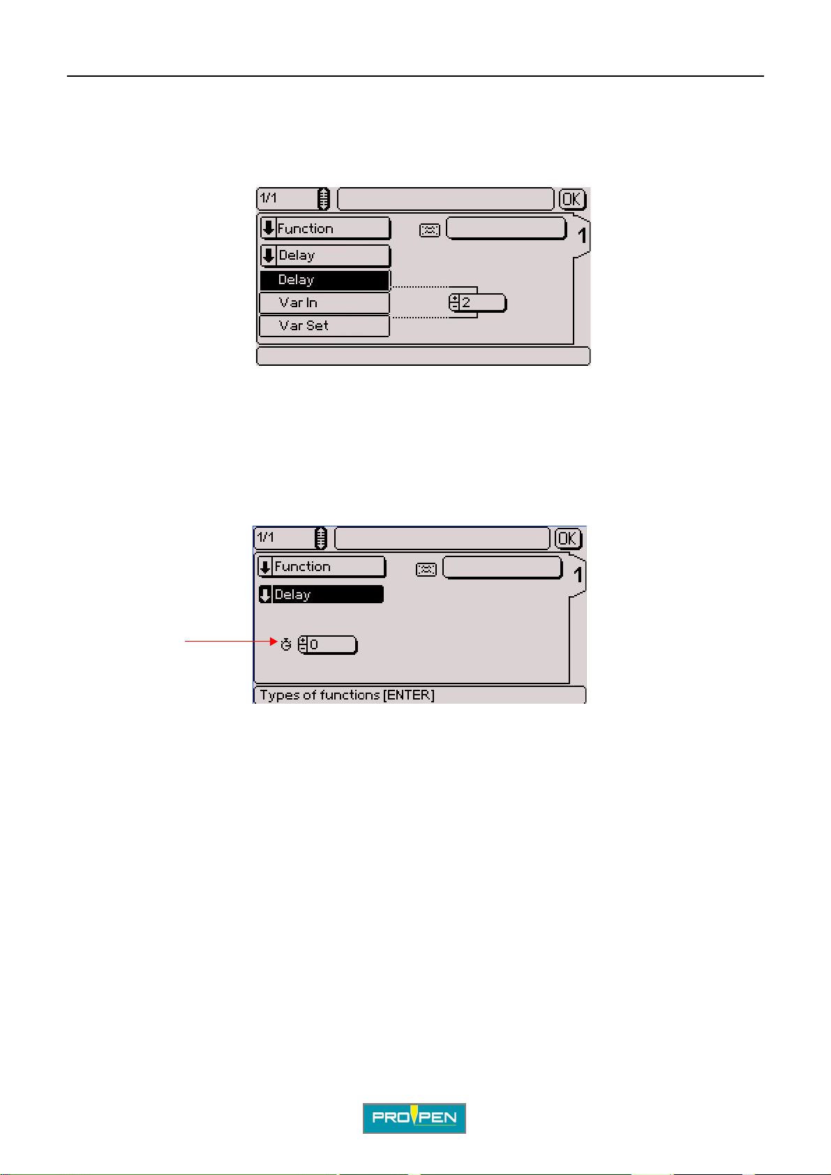
When the "Function" marking type is select ed, choose the desired type of function. Posit ion the cursor on the
"Function types" field. Press En ter to access the entry field. The screen below appear s:
Select the function type using the Up - Down arrows. Validate by pressing Enter.
• Delay
C
This instruction is used to program a pause between the marking of two consecutive marking blocks. The time is
expressed in milliseconds.
The screen below appears:
1
1 : Pause time in milliseconds
The machine waits the time shown before going on to the following block.
Ref. 92091 - P05_en_F
32/121
Page 33
A"Edit file" menu
•Var in
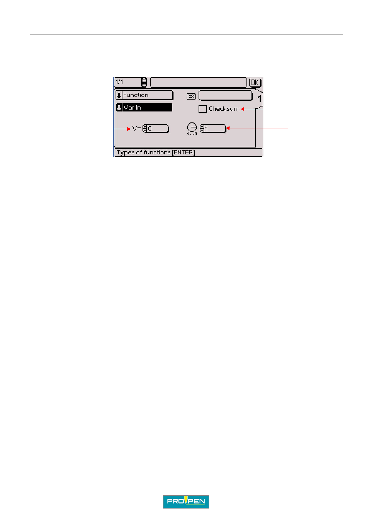
Allows the reception in a variable of a new character string received via the RS232 communication.
The screen below appears:
2
C
1
1 : Number of the variable in which is memorized the character string 2 : Checksum 3 : Batch: number of markings to be carried out with this variable before proposing to re-program the variable
Note: The "Raw data" box must be ticked in the "Communication" menu - "Serial management". See
page(s) 92
Select the number of the variable in which is memorized the character string received.
Choose the number of markings that have to be made before the reception of the following data:
• 1: data reception required at each marking.
• 0: data reception required once at the first marking (even if the fi le is to be marked several times).
During the marking of a "Var in" block, the machine emits an data acquisition re quest (U<CR>) on the RS232
communication and expects an answer from the connected peripheral.
The peripheral must answer by a series of bytes ending by < CR>.
The machine answers V<CR> if successful or T<CR> if failed.
If successful, the character string is stocked in the specified variable.
If failed, the machine waits for new dat a tra nsmission.
3
The data acquisition has suc ceeded when the checksum received is equal to the checksum calculated or when
the checksum is not used.
The checksum is added at the end of the message. It is represented by 2 consecutive characters (0 to F, in
hexadecimal mode).
The emitter calculates the checksum based on the useful data in the transmitted message.
The receiver also calculates the checksum based on the useful data transmitted, and compares this new
checksum to the one received.
The checksum is calculated us in g an "excl usive Or " (XOR) bet ween all the char act ers cont ained in the usef ul pa rt
of the message.
• emission checksum = "character 1 emitted " XOR "character 2 emitted" XOR ... "character n emitted"
• receiving checksum = "charact er 1 received" XOR "character 2 recei ved" XOR ..."character n received"
Ref. 92091 - P05_en_F
33/121
Page 34
A"Edit file" menu
Example
Given the message "ABCD": Checksum calculation: 65 XOR 66 XOR 67 XOR 68
Calculation Characters Decimal Binary Result
A 65 01000001
XOR B 66 01000010
00000011
XOR C 67 01000011
01000000
XOR D 68 01000100
00000100
The result of the message ABCD is: 00000100 in binary, or 04 in hexadecimal mode.
The emitter sends the message ABCD04.
Var in: Use of a marking file
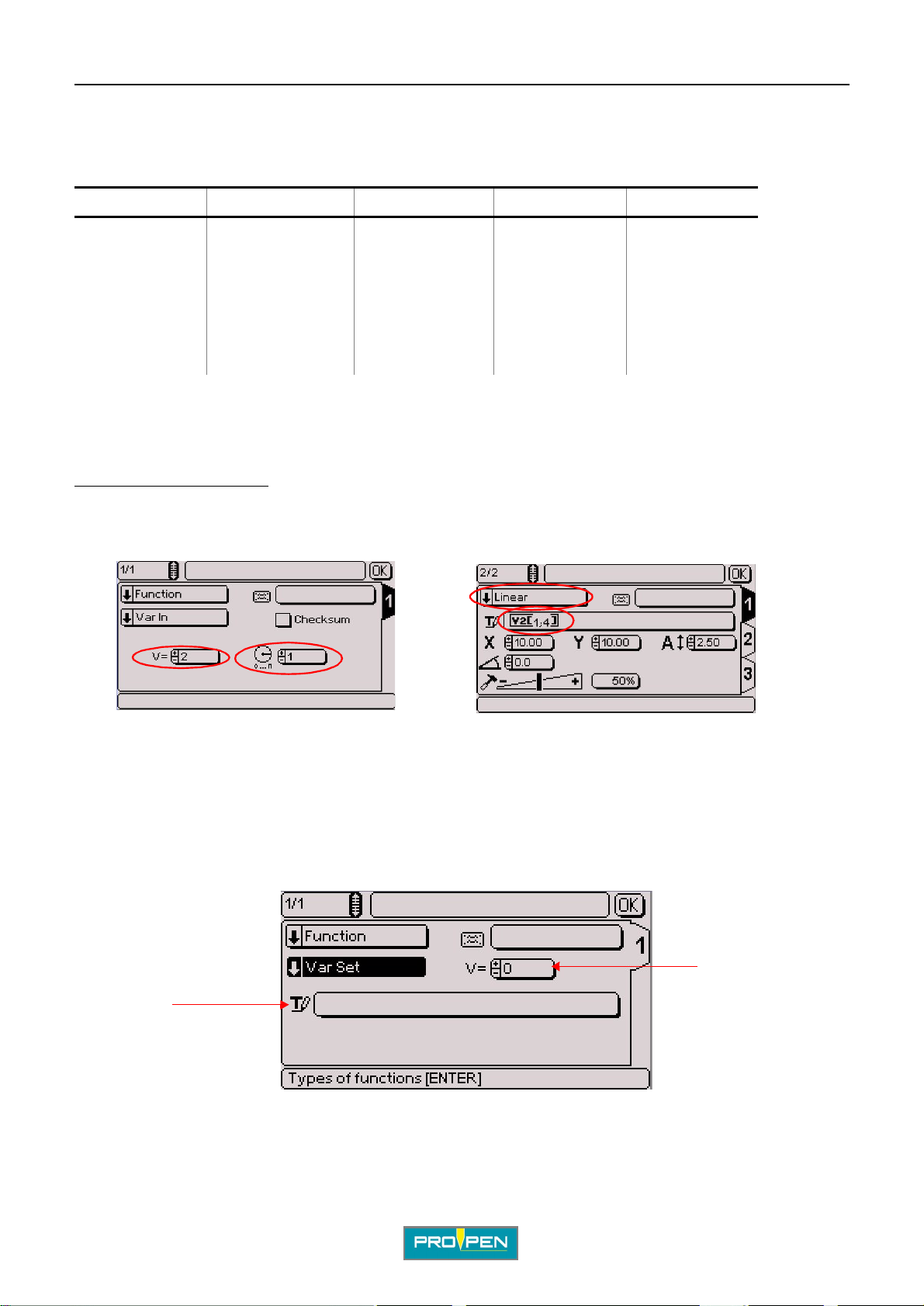
Example:
C
Block 1: Block 2:
The text is saved in variable V2. Only the character string included between characters 1 and 4 is marked. See:
"Splitting a variable:"
A request for data acquisition is necessary each time the file is marked because the batch is set at 1.
•Var set
Used to memorize a character string in a variable.
The screen below appears:
2
1
1 : Entering text in a selected variable 2 : V: number of the variable in which the "Text" field is saved, from V0 to V9
The "Text" field may contain set text, key words (date, hour...), the content of a counter, etc...
Ref. 92091 - P05_en_F
34/121
Page 35
A"Edit file" menu
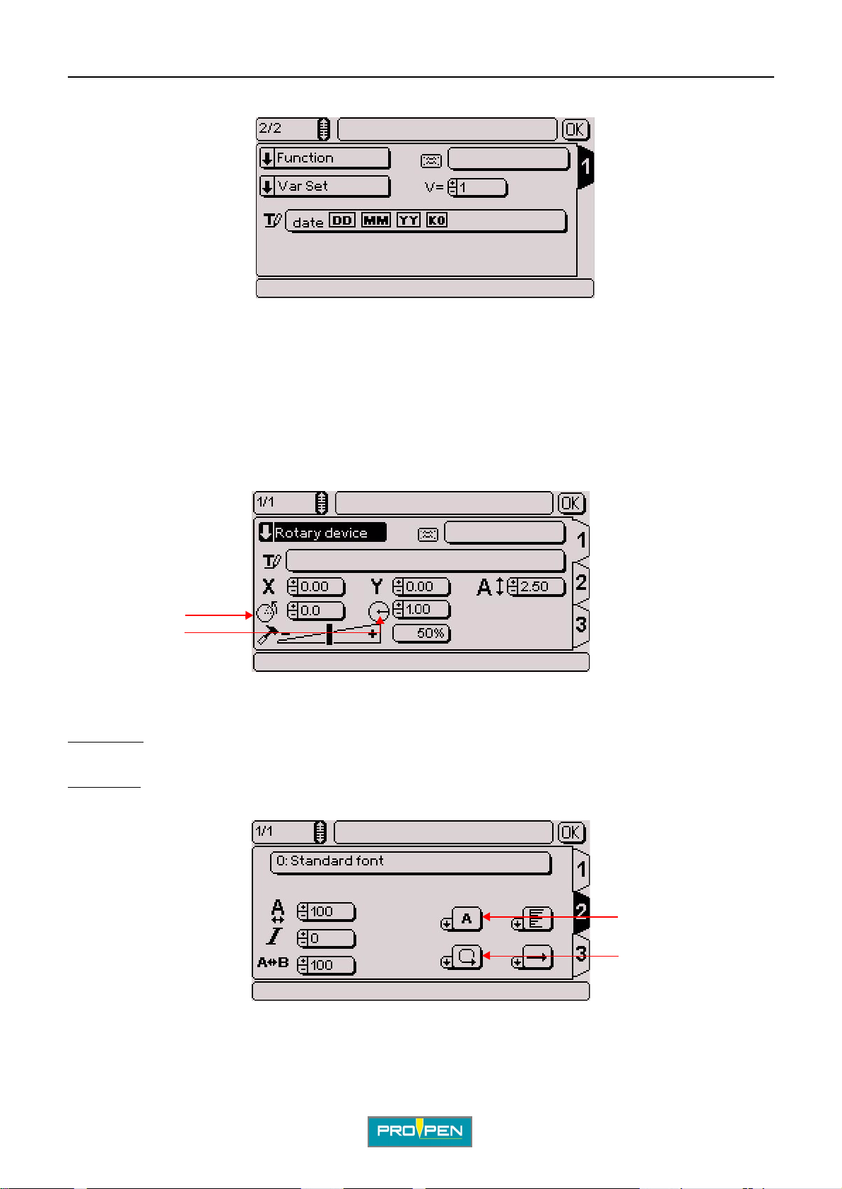
Example:
To mark the memorized content i n the V1 variable, create a linear marking block containing the keywor d V1. See:
"Key words"
Marking obtained: date 05 11 07 001
Rotary device (optional)
Used to mark cylindrical p arts thanks to a rotary marki ng device.
This block type is viewed on the screen only if the device is installed on the machine.
C
Two new data entry fields appear on the screen.
1
2
1 : Initial angle (degrees) 2 : Part radius (degrees)
Initial angle: Used to define the reference angle of the marking on the rotary device. Depending on the alignment
selected, the marking will be left or righ t aligned or centered in relation with this angle.
Part radius:
To enter the other information concerning the rotary device, go to tab 2. The screen below appears:
Used to adapt the marking to the type of part underway.
1 : Writing direction on the rotary device 2 : Rotary device rotation direction
Ref. 92091 - P05_en_F
1
2
35/121
Page 36
A"Edit file" menu
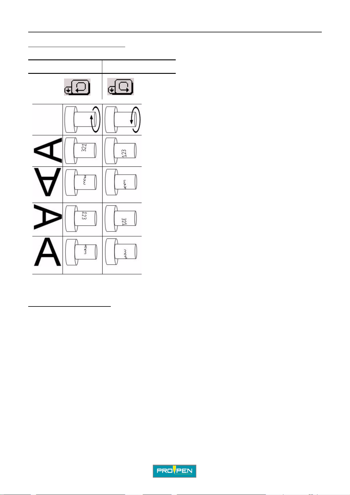
Writing direction on the rotary device: Used to determine character orientation.
Rotary device positionned on the origin side
Clockwise Counter-clockwise
C
Rotary device rotation direction:
Counter-clockwise direction selected by default.
Ref. 92091 - P05_en_F
clockwise / counter-clockwise
36/121
Page 37
A"Edit file" menu
Text to be marked
Enter the text to be marked in the appropriate block. The text may be composed of:
• capital / low er case letters
•numbers
•key words
The maximum number of characters per block is 255.
The characters that can be marked depend on the font.
Key words
Key words are codes interpreted by the progra m. They are not actuall y marked but rather "sa ved" before markin g.
It is possible to define several keywor ds in the same text area.
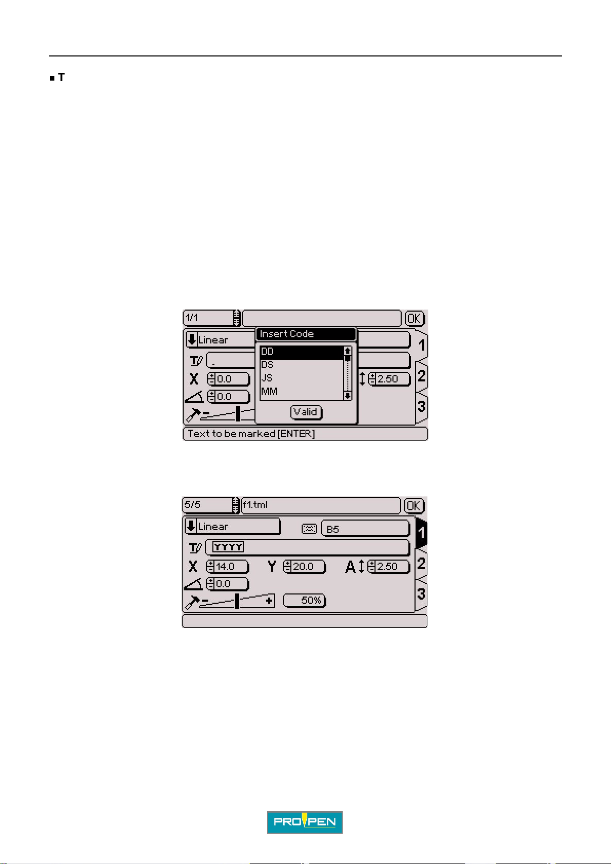
To enter a keyword, press the Insert key on the keyboard in the "Text" area. The list of keywords appears. Select
the desired keyword using the Up - Do wn arrows or by typing the fi rst l ette r of t he key word to be i nserted. Validate
by pressing Enter.
C
The keywords are indivisible units. When a keyword is inserted, it appears in a frame, it is impossible to delete
part of akeyword. Each keyword is considered a single character.
Ref. 92091 - P05_en_F
37/121
Page 38
A"Edit file" menu
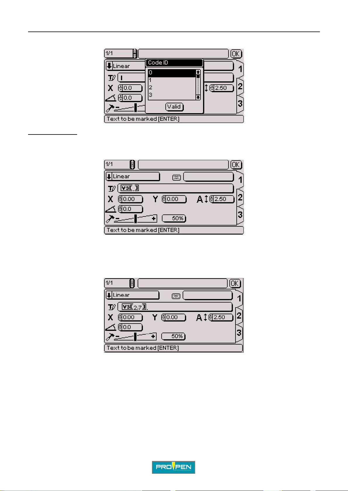
For Kn - Vn keywords, a second window appears to select the variable number .
Splitting a va riable:
A portion of the contents of a variable may be selected and marked.
When a variable is inserted in text, the screen below appears:
C
To mark all the content of the vari able, leave the brackets empty.
To mark part of the content of the variable, indicate between brackets the first and last char acter to take into
account, seperated by a semi-colon (;).
Example:
Contents of variable V3: ABCDEFGHIJ Marking obtained: BCDEFG
The 0 number represents the end of the variable. Example: V3[4;0] Marking obtained: DEFGHIJ
It is possible to mark the content of a variable from right to left.
Example 1: V3[5;1]
Marking obtained: EDCBA
Example 2: V3[0;4] Marking obtained: JIHGFED
Ref. 92091 - P05_en_F
38/121
Page 39
A"Edit file" menu
List of key words
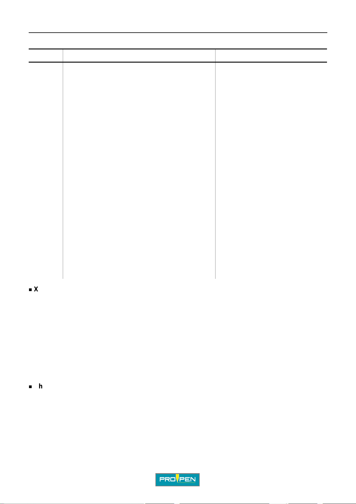
Key words Definition Marking
DD number of the day in the month (from 01 to 31) 09 - for the 9th day in the month
MM month number (01 to 12) 05 - for the month of May
YYYY year in 4 digit(s) 2007
YY year in 2 digit(s) 07
Y year in 1 digit(s) 7
hh hours (00 to 23) 12 - for 12 h 28 min 35 sec
mm minutes (00 to 59) 28 - for 12 h 28 min 35 sec
m first number for block of ten minutes (1 to 5) 2 - for 12 h 28 min 35 se c
ss seconds (00 to 59) 35 - for 12 h 28 min 35 sec
WW week number (01 to 53) 01 - for January 3 2001
CCC number of the day in the year (001 to 366) 028 - for January 28 2001
HS time interpretatio n code
DS interpretation code for the day of the week
C
JS interpretation code for the day of the month
MS interpretation code for the month
YS interpretation code for the year
Kn interpretation code for the counters (K0 to K9)
Q interpretation code for shifts according to time block
Vn
Vm last text marked
X-Y coordinates
interpretation code for variables
See: “"Variables" menu”
The X-Y coordinates determine the position of the text in the marking zone. They are given:
• in millimeters or in inches, depending on the unit chosen
• with an accuracy of 0.1 mm (0.01 in) in manual entry mode (0.5 mm (0.02 in) with the +/- keys on the numeric
keypad)
• in absolute value with relation to the origin
The coordinates can be entered either by:
• using the +/- keys on the numeric keypad
• pressing Enter then by typing the value directly on the keyboard
Character size
The "Size" field defines the actual height, in either millimeters or inches , of char acters marked in capital letter s.
The size can range from 0.5 mm (0.02 in) to 100 mm (3.937 in). The accuracy is to 0.01 mm (0.01 in) in manual
entry mode (0.1 mm (0.01 in) with the +/- keys on the numeric keypad).
The default value is 2.5 mm (0.10 in).
Ref. 92091 - P05_en_F
39/121
Page 40
A"Edit file" menu
Text angle
Used to define the angle at which the text is marked. See: “Linear marking”.
°
The default value is 0
Marking force
The width and depth of the marked line varies with the defined value.
The higher the force, the deeper the mark. This value is expressed as a percent. The default value of the "F orce"
area varies according to the machine’s configuration.
TAB 2:
Once all these fields a re fi lled, use the keyboard’s Tab key or arrows to switch to t ab 2 in order to pro ceed wi th the
preparation of the block. The tab number appears in reverse video.
.
C
1
2
3
5
6
7
4
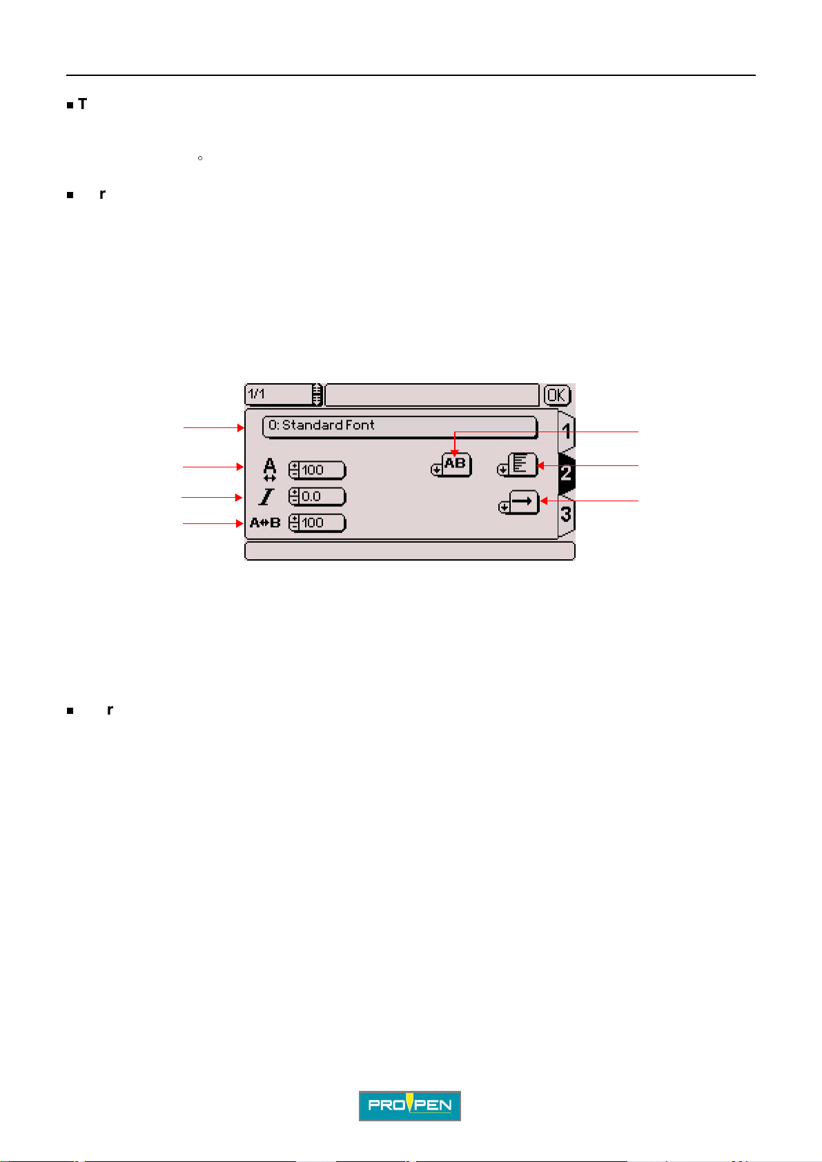
1 : Character font 2 : Compression 3 : Inclination 4 : Spacing 5 : Marking effects 6 : Alignment 7 : Marking direction
Character fonts
The various fonts saved are identi fied by a number followed by their name. Go to the font area to sele ct th e
character font to be used in the marking block being prepared.
By default, the program uses a standard font:
- # 0 - continuous stroke - for pneumat ic machines
- # 3 - dot by dot - for electromagnetic machines
Ref. 92091 - P05_en_F
40/121
Page 41
A"Edit file" menu
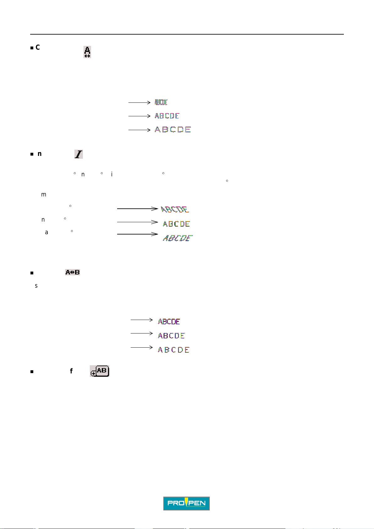
Compression
Used to modify character width without modifying height. The compression factor mod if ies the space between
characters. This value i s expresse d as a per cent. It must be between 25% and 300%, wit h increment s of 5%. The
default value is 100%.
Example:
Compression 50%:
Compression 100%:
Compression 150%:
Inclination
Used to determine the v alu e, in degrees, o f the incl ination a ngle of t he characte rs in relat ion t o the ver tical. It must
°
be between -85
value is negative, the characters slant to the left. The default value is 0
Example:
Inclination -30
and +85°, with increments of 5°. If the value is positive, the characters slant to the right. If the
°
.
°
:
C
°
Inclination 0
Inclination +30
Spacing
Used to modify the inter-character spacing, without changing their width or height. This value is expressed as a
percent. It must be between 25% and 300%, with increments of 5%. The default value is 100%.
Example:
Spaci ng 50% :
Spaci ng 100% :
Spaci ng 150% :
Marking effects
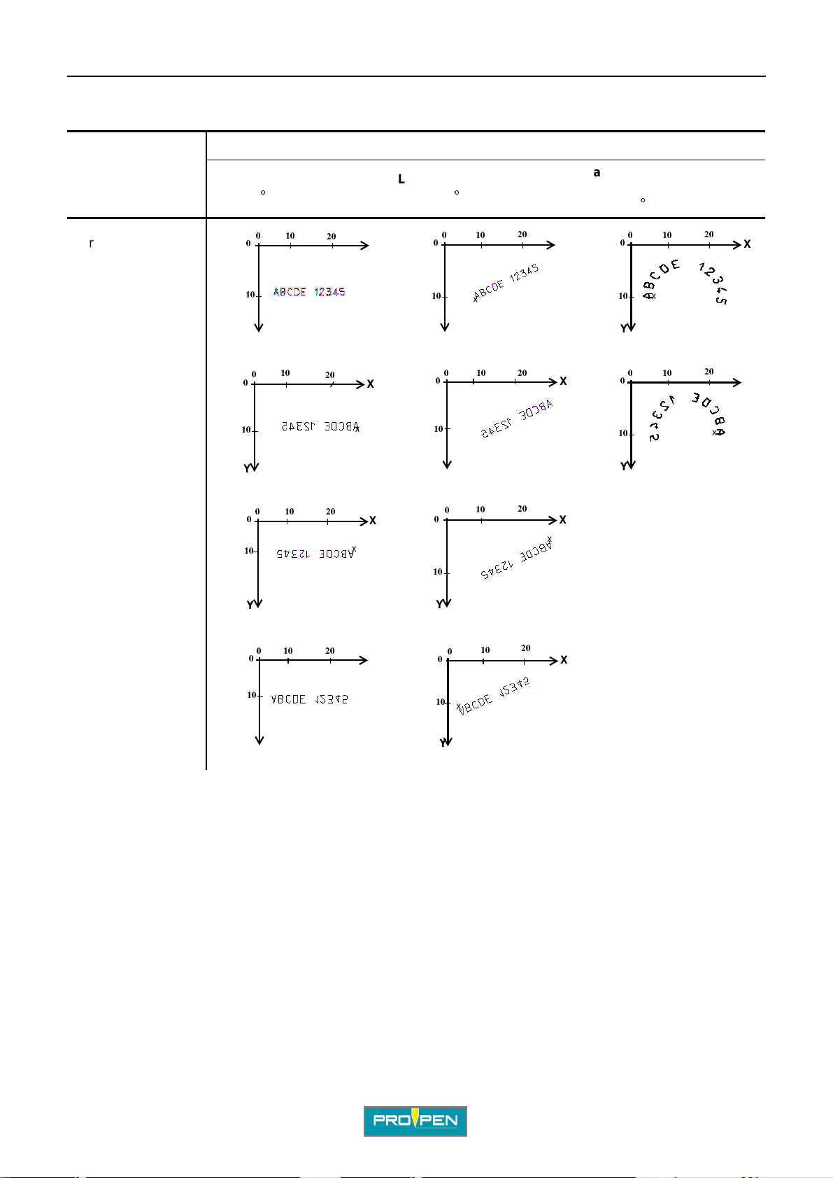
Several marking directi ons are proposed in order to adapt marking to th e specificities of certain parts.
In radial mode, only the normal and mirror effects are available.
:
°
:
Ref. 92091 - P05_en_F
41/121
Page 42
Marking obtained:
A"Edit file" menu
C
Result
Marking effects
Normal
Mirror: symmetry
along Y
Inverted: symmetry
along X-Y
Linear marking
Angle: 0
°
10
0
0
x
10
Y
10
0
0
10
Y
10
0
0
10
Linear marking
Angle: 35
20
20
20
X
X
x
X
x
°
010
0
10
x
Y
10
0
0
10
Y
10
0
0
10
20
20
20
Radial marking
Centering
Angle: 90
X
X
x
X
x
°
010
0
10
x
Y
010
0
10
Y
20
X
20
X
x
Y
Reflected: symmetry
along X
0
0
x
10
Y
20
10
X
The X represents the start marking point (X-Y coordinates).
Y
20
10
0
0
10
x
Y
X
Ref. 92091 - P05_en_F
42/121
Page 43
A"Edit file" menu
0
Alignment
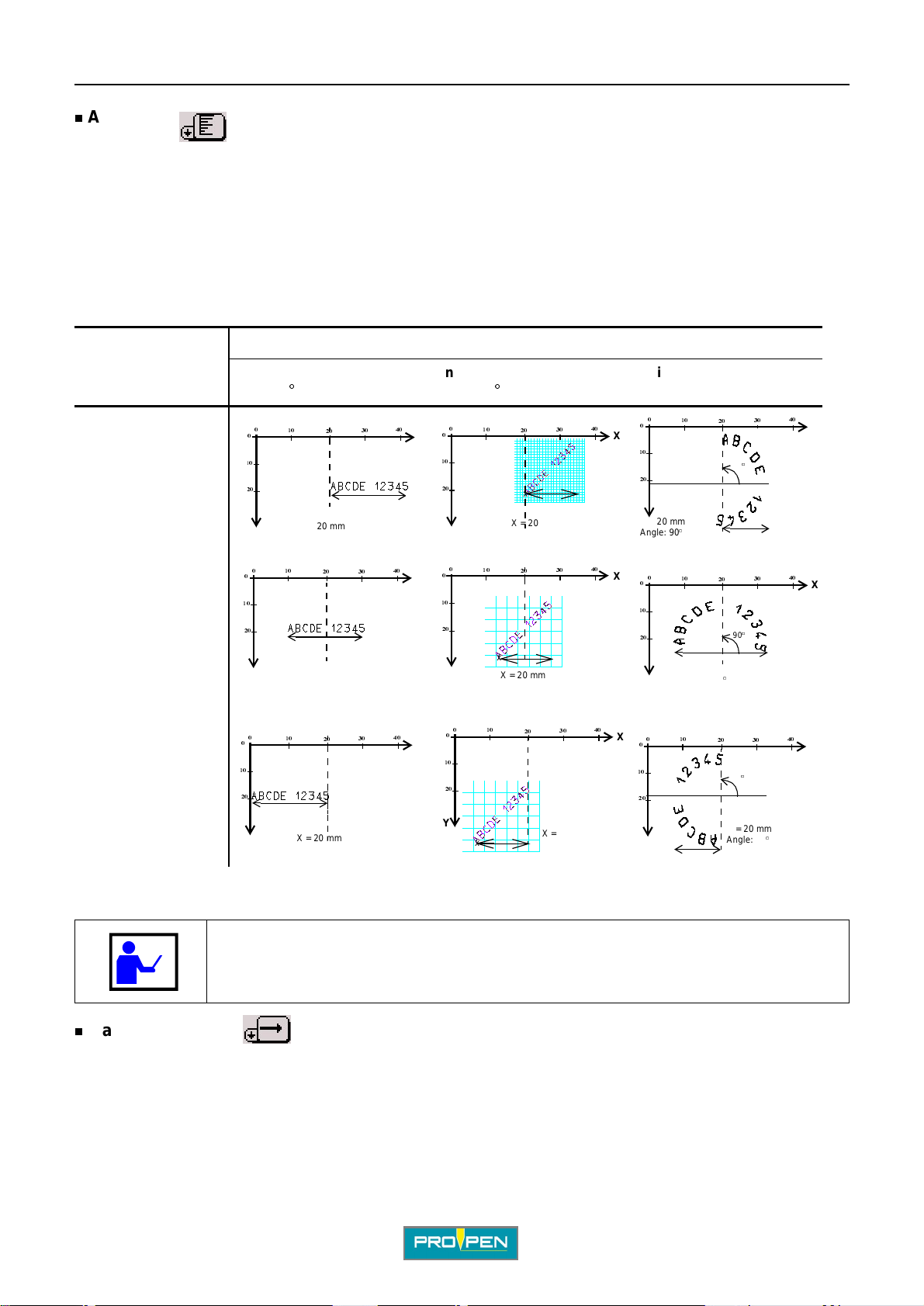
Used to align the text to the left, right or center.
In case of left alignment to, the value of X corr esponds to the beginning of the text to be marked.
In case the text is centered, the value of X corresponds to the center of the text to be marked.
In case of right alignment, the value of X corresponds to the end of the text to be marked.
In radial mode, text justification is done in relation to the start angle.
By default, the text is aligned to the left.
Examples
Result
Alignment
Linear marking
Angle: 0
°
Linear marking
Angle: 45
°
Radial marking
Clockwise marking
C
Left alignment
Centering
Right alignment
0
10
°
10
x
X = 20 mm Angle: 90
10
20
x
20
°
20
90
X = 20 mm
x
Angle: 90
90
°
90
°
°
0
0
10
20
0
0
x
40
30
X
X = 20 mm
0
10
0
10
20
20
x
40
30
X
10
0
10
20
20
x
X = 20 mm
0
10
0
10
20
20
40
30
40
30
X
X
0
10
20
X = 20 mm Angle: 90
0
0
10
20
x
X = 20 mm
0
0
10
0
10
20
x
Y
20
X = 20 mm
40
30
0
X
10
20
Y
x
X = 20 mm
10
20
30
X = 20 mm
40
X
0
0
10
20
40
30
30
30
X
40
X
40
X
°
The X represents the start marking point (X-Y coordinates).
The text to be marked may become of f-li mit s i f the X or Y val ue, or th e charac ter size,
is too large. To correct this anom aly, reduce or increrase one or the other of these
values.
Marking direction
Used to choose the movement direction of the stylus dur ing marking, from left to right or from right to le ft. This
function is used to optimize marking time and must not be confused with the direction of writing (marking effects).
The default marking direction is from left to right.
Ref. 92091 - P05_en_F
43/121
Page 44
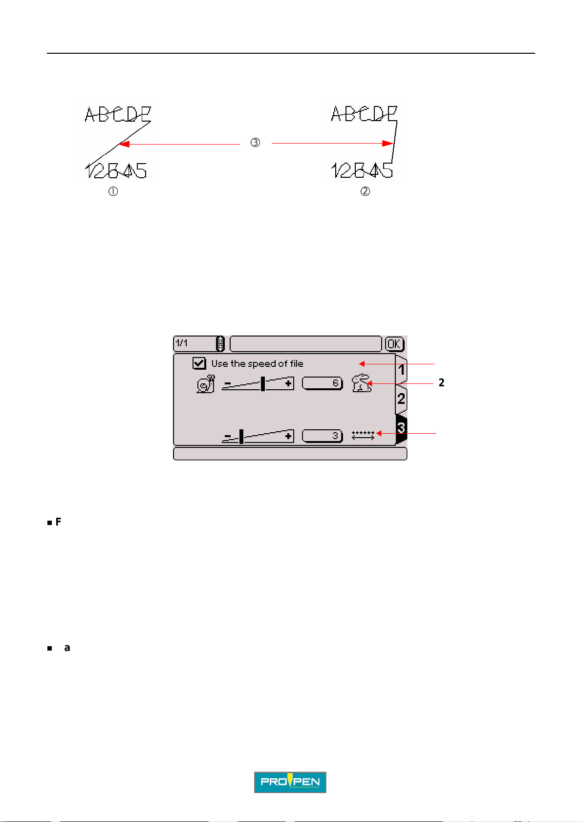
A"Edit file" menu
In the following example, the marking direct ion fr om right to lef t r educes the movement s of th e stylus between t he
first block and the second one.
C
1 : Marking direction from left to right for the 2 blocks 2 : Marking direction from right to left for the second block 3 : Segments of movement of the stylus
TAB 3:
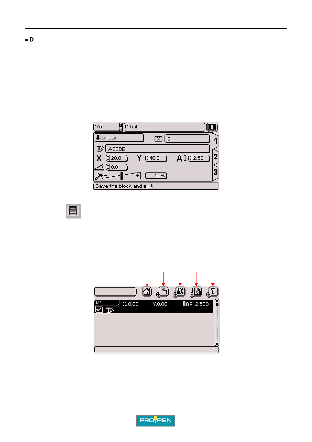
Once all these fields a re fi lled, use the keyboard’s Tab key or arrows to switch to t ab 3 in order to pro ceed wi th the
preparation of the block.
1
2
3
1 : File speed option 2 : Marking speed 3 : Dot density per millimeter (electromagnetic version only)
File speed option
If this option is activated, the speeds chos en for the file in the sub-menu "File - Properties" are applied to the
block.
When the option is activated, it is impossible to modi fy the values on screen. To customize the speeds in the
block, deactivate this option by pr essing Enter.
This option is activated by default.
To choose the speeds of the file : See: "Pr operties of the file (F12)"
Marking speed
Used to determine the speed of the stylus.
This value must be between 1 and 10. The default value is 6. From 1 to 7, speed increases with an optimum
quality of marking. From 8 to 10, quality gradually decreases in order to privilege speed. The faster the marking,
the lower the quality. A very high quality marking re quires a slow marking speed.
Ref. 92091 - P05_en_F
44/121
Page 45
A"Edit file" menu
Dot density per millimeter (electromagnetic version only)
Used to define the number of dots per milli m eter produced by the stylus, in electromagnetic.
The higher the density, the closer the dot s are to each other. The default value is 3.
The density also depends on the speed select ed. As speed in crea ses, the dens ity of dot s per mi llimeter becomes
limited.
2. "Edit" men u su b- me n us
Once the preparatio n of the block is complete, move t o the "OK" button using the key board’s arrow keys or press
Esc to validate the block and exit.
C
The program returns to the marking file and the sub- me nus can then be accessible using the Context menu key
on the keyboard. They are used to edit the file in progress.
To switch from one menu to another, use the Left - Right arrows.
To scroll a menu, press Enter or the Down arrow. If the functions are not fully displayed in the sub-menu, the
description is shown in the pop-up help bar at the bott om of the scr een.
To close a menu, press the Up arrow.
To return to the blo cks and leave the sub-menus, press the Context menu key on the keyboard.
12345
1 : "Marking" sub-menu
2 : "View" sub-menu
3 : "Edit" sub-menu
4 : "File" sub-menu
5 : Back to the previous menu
Ref. 92091 - P05_en_F
45/121
Page 46
A"Edit file" menu
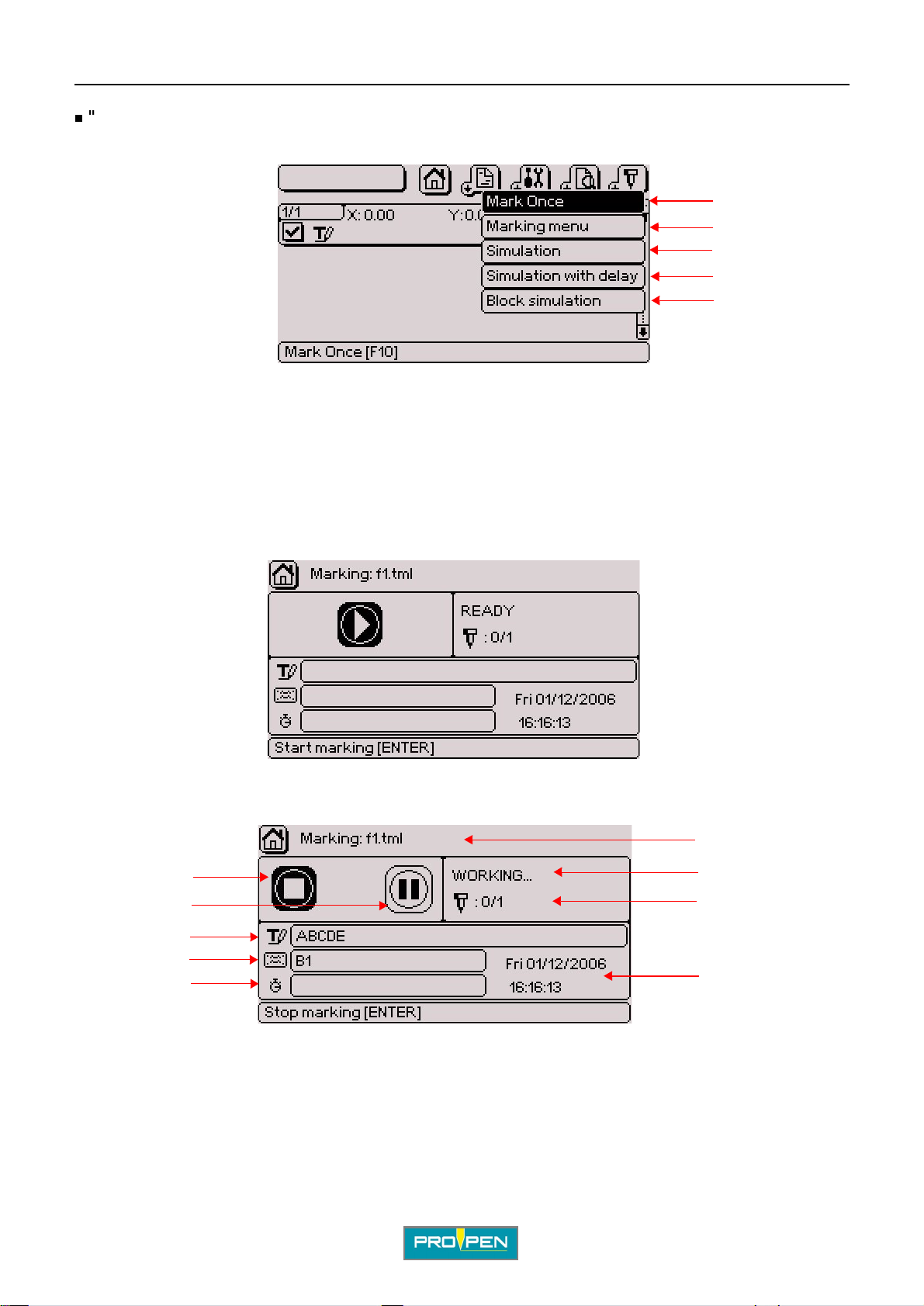
"Marking" sub-menu
Used to access certain functions of the "Marking" menu directly from the file.
1 : Marking a file
2 : Access to the "Marking" menu
3 : Marking simulation
4 : Marking simulation with pause
5 : Simulation of the current block
Marking a file (F10)
C
1
2
3
4
5
Used to mark the file in progress "one time".
The screen below appears:
Press Enter to launch the mar king cycle. During the marking of each block, the corresponding characteristics are
shown on the screen.
6
1
2
7
8
3
4
5
9
1 : "Stop marking" icon
2 : "Pause during marking" icon
3 : Text for the block being marked
4 : Name of the block being marked
5 : Marking time. Appears once the markings are completed.
6 : Name of the file being marked
7 : Status of marking
8 : Number of markings carried out in relation to the total number of markings to be done
9 : Current time and date
Ref. 92091 - P05_en_F
46/121
Page 47
A"Edit file" menu
In addition to the information relative to the block being marked, this screen indicates the marking status, the
number of markings performed and the total duration of marking.
It is possible to pause during marking or to stop the latter by moving onto the corresponding icons. See: "Marking
"N times"".
Access to the "Marking" menu
Used to access the complete "Marking" menu. See: ""Marking" menu".
Simul a tio n (F 9 )
Used to simulate the marking file. Simulation consists in performing the marking without activating the stylus.
Simulation is carried out as a "one time" marking. See: "Marking a file (F10)".
Marking simulation with pause
This function is id enti cal to the marking simulation, with a pause after each block. To continue the simulation after
each block, press Enter.
C
Simulation of the current block (F4)
Used to carry out a marking simulation of the marking block under preparation. The simulati on is carried out for
just one block.
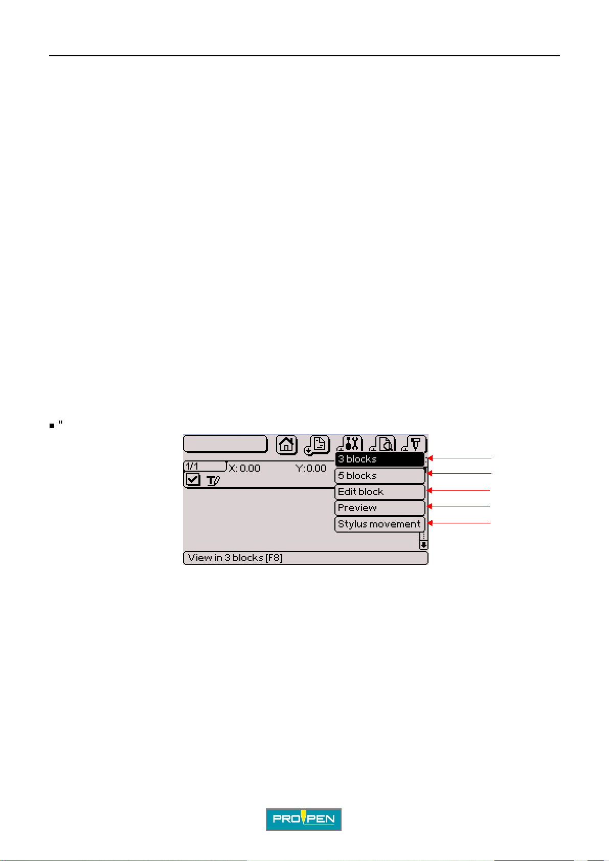
"View" sub-menu
1
2
3
4
5
1 : View 3 blocks
2 : View 5 blocks
3 : Edit block
4 : Graphic preview before marking
5 : Stylus movement
In 3/5 blocks display mode, it is possible to insert a pause after a block. When this function is activated, the
machine pauses after the block concerned. Press "Start marki ng" to continue marking.
Ref. 92091 - P05_en_F
47/121
Page 48
A"Edit file" menu
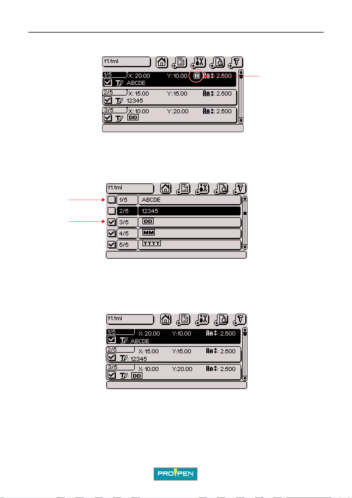
To insert a p ause after a block, posit ion t he cursor on the bl ock in 3/ 5 blocks displ ay and simul taneo usly pr ess Ctrl
+ P on the keyboard. A symbol is shown:
Pause after a block
Activation / deactivation of the bloc ks
Used to deactivate a block from a marking file. A deactivated block is not marked.
To deactivat e a block, po siti on the curs or on t he desire d block and pr ess the sp ace bar. A deactivated block is not
checked off, an activated bl ock is checked off.
C
1
2
1 : Deactivated block
2 : Activated block
To reactivate the block, repeat the operation.
View 3 blocks (F8)
Used to view the blocks by groups of 3 on the screen.
The following characterist ics are shown:
• block number
• X-Y coordinates
• character size
• text to be marked
• activated block / deacti vated block
• pause after block if activated
Ref. 92091 - P05_en_F
48/121
Page 49
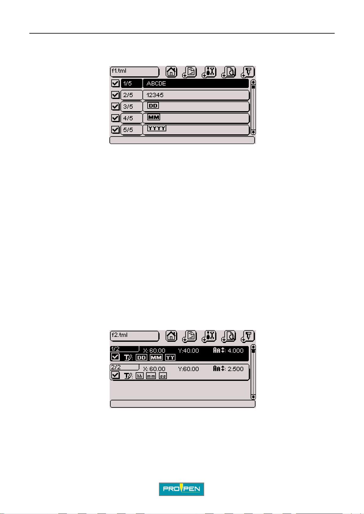
A"Edit file" menu
View 5 blocks (F8)
Used to view the blocks by groups of 5 on the screen.
The following characterist ics are shown:
• block number
• text to be marked
• activated block / deacti vated block
• pause after block if activated
C
In these two viewing modes, to see the details of a speci fic block, select the Up - Down arrows on the keyboard.
Validate by pressing Enter.
Edit block (F8)
Used to access the details of a block. This fun ction can also be achi eved by select ing a block and pressing Enter.
Graphic preview before marking (F2)
Used to:
• screen preview of all data ent ered in the marking file.
• view the trajectory of the stylus.
Example of a file:
Ref. 92091 - P05_en_F
49/121
Page 50
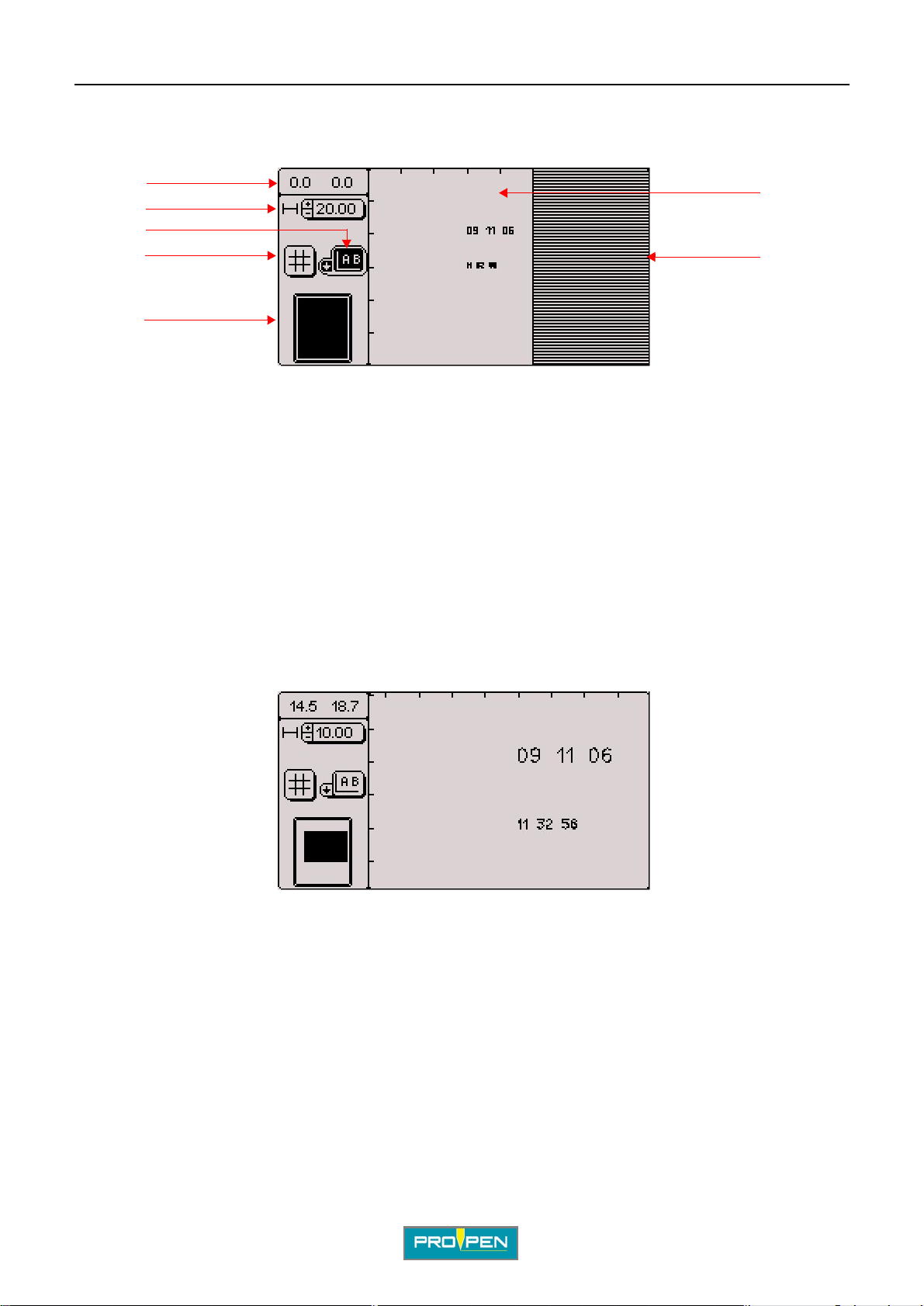
A"Edit file" menu
Screen preview of the marking file:
Select "Preview" in the "View" sub-menu. The screen below appears:
C
1
2
3
4
5
1 : X-Y coordinates (top left corner)
2 : Scale - Zoom in / zoom out
3 : View with or without the stylus trajectory
4 : Grid
5 : Global view of the marking area
6 : Marking zone
7 : Off-limits zone
The screen is divided into 2 part s: the control bar on the l eft and the preview zone on the ri ght. To go from one part
to the other , press the Context menu key on the keyboard.
6
7
Scale: Select the scale using the +/- keys on the numeric keypad. The selected scale defines the zoom.
Zoom in / zoom out: actual or enlarged view of the marking
To move when the marking field is not entirel y visible, press the Context menu key on the keyboard then move
using the arrows.
To regain access to the opti ons on left of the screen, press the Context menu key on the keyboard once more.
Ref. 92091 - P05_en_F
50/121
Page 51
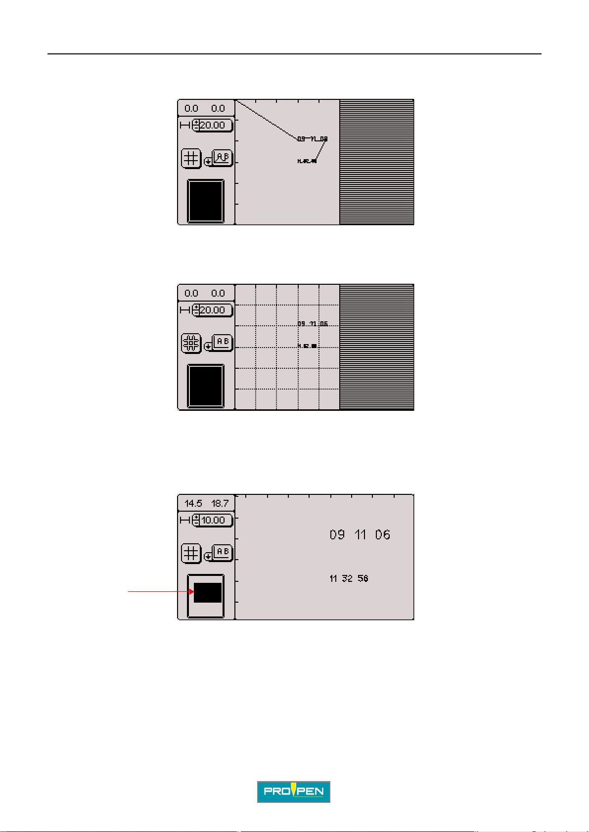
A"Edit file" menu
Segments of movement of the stylus: preview of the exact path of the stylus, broken down segment by segment,
from the starting point to the end point
Grid: grid overlaps the marking surface
C
Global view of the marking area: The black area represents what is visible on the scre en.
At the 20 mm (0.787 in) scale, the whole marking field is visible on the screen. When the scale increases, onl y a
part of the field is displayed on the screen. This view allows to locate the position within the marking field.
1
1 : The black square represents the zone displayed on the right of the screen in relation to the entire marking field.
Ref. 92091 - P05_en_F
51/121
Page 52
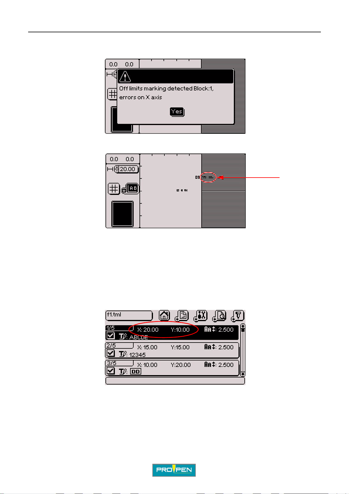
A"Edit file" menu
If the text to be marked is off-li mits, a warning message is displayed at the preview, even when the off-limits
control is deactivated.
Validate by pressing Enter. The part of the text of f- li mits is shown in the hatched area.
1
C
1 : Text off-limits
Return to the marking file and modify the coordinates.
Stylus movement (F3)
The "dynamic adjustment" function i s used to move the stylus above the surface to be marked in order to
determine the start marking coordi nates.
Position on the chosen block. The screen below appears:
Ref. 92091 - P05_en_F
52/121
Page 53
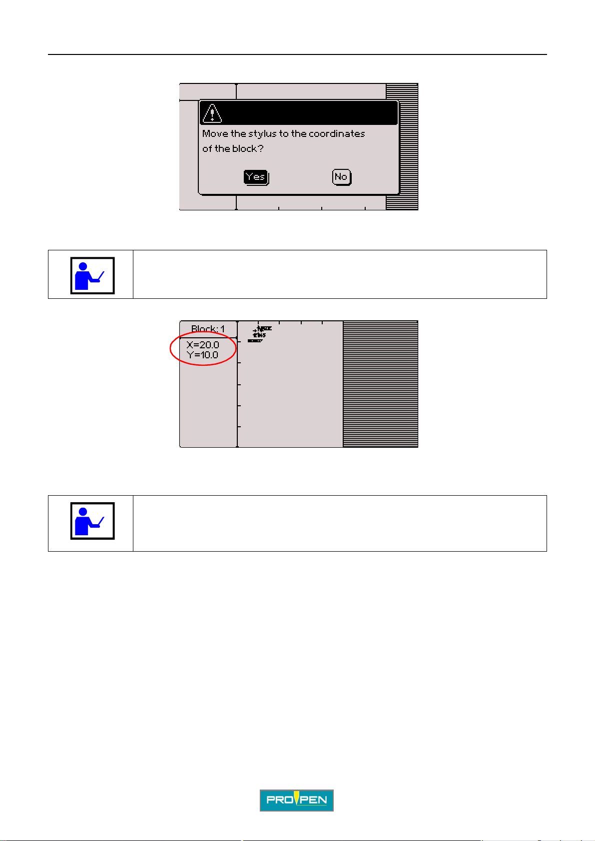
A"Edit file" menu
Press F3 to reach the "Stylus movement" in the "View" submenu. The screen below appears:
Yes: The stylus moves to the X-Y coordinat es of the marking block. No: Return to previous screen
Before answering "yes", make sure that no obstacle is in the stylus’ trajectory.
The screen below appears:
C
For a "Rotary device" block type, the initial angle is viewed on the display, under the X-Y coordinates.
The stylus moves to the X-Y coordinates of the marking block. In the example, X = 20 and Y = 10.
To adjust the stylus position, press the Up - Down - Left - Right arrows alternately.
The numeric keypad keys can also be used to move the stylus. The 5 key of the
numeric key pad brings the sty lus back to ori g in.
Page Up - Page Down keys are used to adjust the initial angle of the rotary device.
Ref. 92091 - P05_en_F
53/121
Page 54
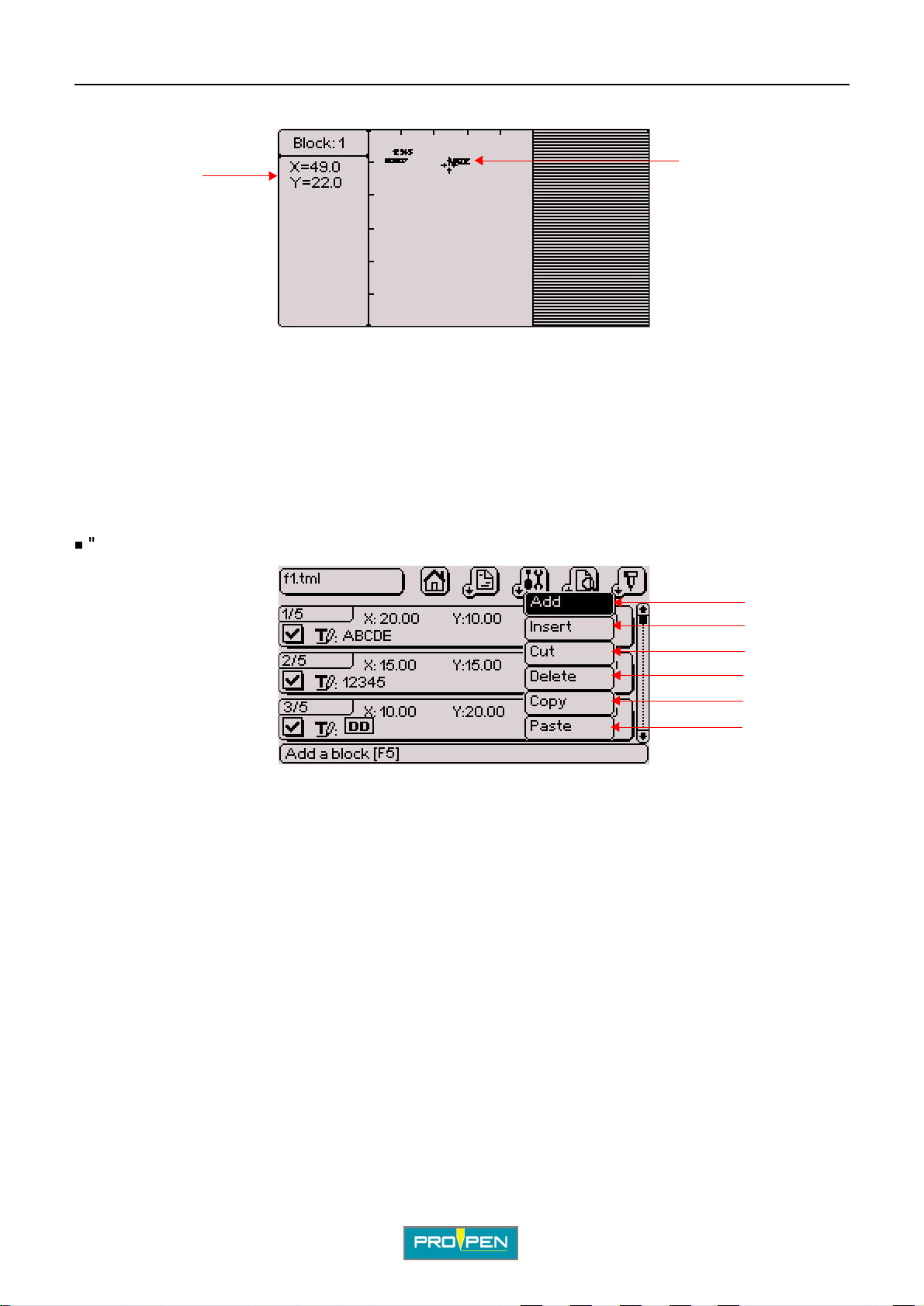
Only the block underway moves.
A"Edit file" menu
C
1
1 : New block coordinates
2 : Block moved
The movement value is 0.1 mm (0.004 in), along X or Y.
When the correct position is reached, validate by pressing Enter. The program returns in the previous page. The
new coordinates appear on the screen.
Esc: return to the file, without saving modifications
"Edit" sub-menu
2
1
2
3
4
5
6
1 : Add a block at the end of the file
2 : Insertion of a block before the selected block
3 : Cut the selected block
4 : Deleting the selected block
5 : Copy the selected block
6 : Paste the stored block
Add a block at the end of the file (F5)
Used to add "empty" marking blocks at the end of a file. The pr ogram then automatically updates the numbering.
Insertion of a block before the select ed block (Insert)
Used to insert an "empty" block before the seleted block.
Select the block and press Insert on the keyboard or go to the "Edit - Insert" sub-menu. The program then
automatically updates the numbering.
Ref. 92091 - P05_en_F
54/121
Page 55
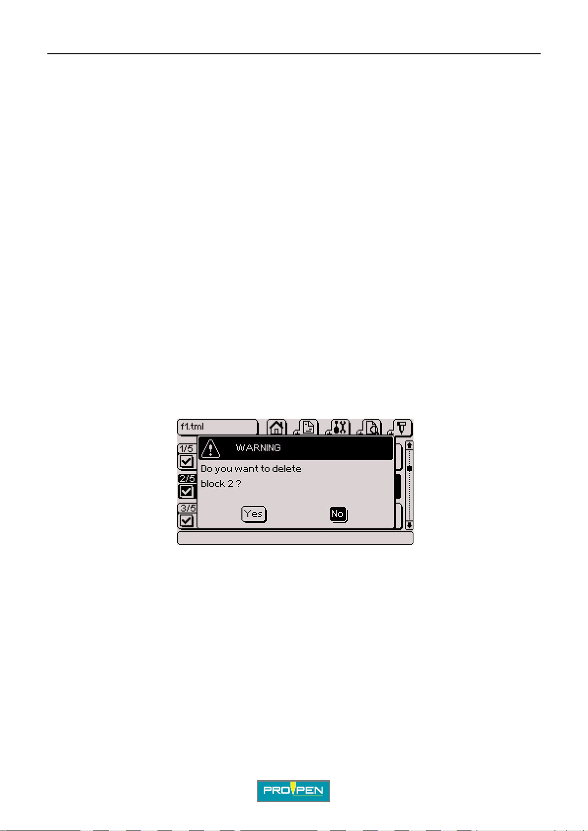
A"Edit file" menu
Cut/paste a block (Ctrl + X - Ctrl + V)
Used to move a block within the file.
Select the block to be cut. Simultaneously press the Ctrl + X keys on the keyboard or go to the "Edit - Cut" sub-
menu. The block is saved in the memory. Position the cursor on the bl ock after which it must be pasted.
Simultaneously press the Ctrl + V keys on the keyboard or go to the "Edit - Paste" sub-menu. The saved block is
pasted after the selected block.
Copy/paste a block (Ctrl + C - Ctrl + V)
Used to copy a block with its character istics.
Select the block to be copied. Simultan eously press the Ctrl + C keys on the keyboard or go to the "Edit - Copy"
sub-menu. The block is saved in the memory. Position the cursor on the block after which it must be pasted.
Simultaneously press the Ctrl + V keys on the keyboard or go to the "Edit - Paste" sub-menu. The saved block is
pasted after the selected block.
Note:
F7: Used to add a block identical to the selected block. The program copies and inserts this new block af ter the
selected block, then updates the numbering.
C
Deleting the selected block (Delete)
Deletes a marking block
Select the block to be deleted and press Delete on the keyboard or go to the "Edit - Delete" sub-menu.
As a precaution, the program will request confirmation before deleting the marking block.
Select "Yes" with the Left arrow and validate by pressing Enter. The program deletes thi s block and updates the
numbering.
Ref. 92091 - P05_en_F
55/121
Page 56
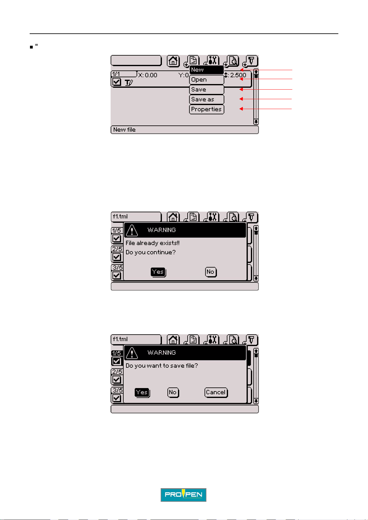
A"Edit file" menu
"File" sub-menu
1
2
3
4
5
1 : New marking file
2 : Open an existing file.
3 : Save the file in progress.
4 : Save as the file in progress.
5 : Properties of the file
Save the file in progress / save as the file in progr ess: F11
To save a file un der a na me, if a file wi th the same n ame alrea dy ex ist s, t he pr ogram i ndicate s that this fil e alr eady
exists and requests confirmation of its replacement.
C
Yes: Overwrite the existing file and replace it with the new one.
No: Return to the marking file without validating modifications
For a file that has not been saved or that has been modified, when pressing Esc, the program asks whether it
should be saved before exiting.
Yes: Save selected file
No: Exit the file without saving
Cancel: Return to the marking file without valid ati ng modifications
Ref. 92091 - P05_en_F
56/121
Page 57
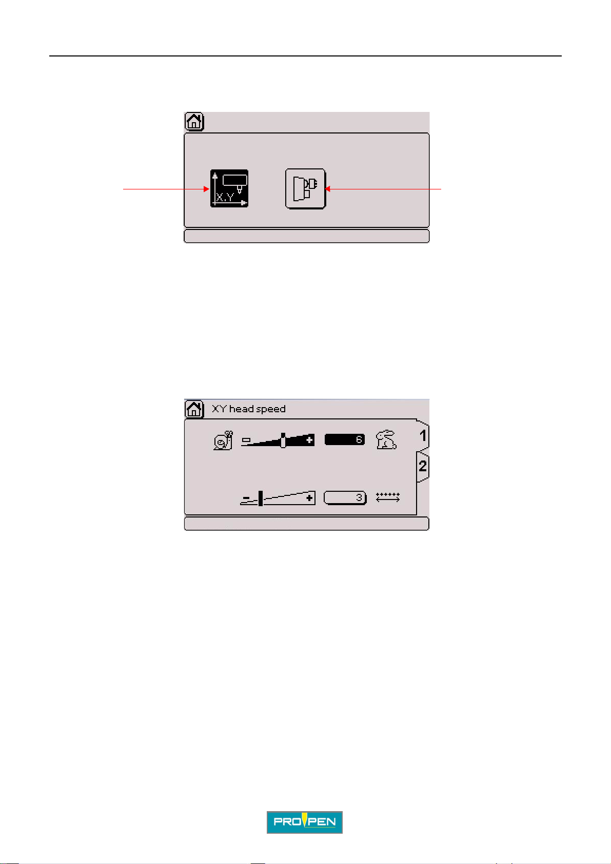
Properties of the file (F12)
The screen below appears:
1 2
1 : XY head marking speed
2 : Rotary device speed
• XY head marking speed
TAB 1:
A"Edit file" menu
C
Used to determine the speeds common to the whole file. These speeds are applied by default to every block on
the file.
The screen below appears:
See: "Marking speed", "Dot density per millimeter (electromagnetic version only)".
Ref. 92091 - P05_en_F
57/121
Page 58
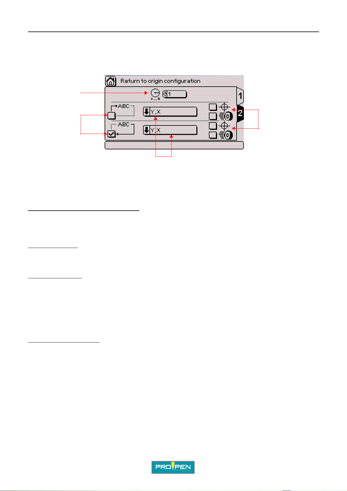
A"Edit file" menu
TAB 2:
Used to configure the return to orig in of the stylus.
The screen below appears:
1
2
1 : Number of markings before return to origin 2 : Start/end file origin 3 : Return to origin type 4 : Accurate mode / fast mode
C
4
3
Number of markings before return to orig in: Used to define the number of marking s the st ylus returns to origin.
If the 1 value is selected, the stylus re turns to origin after each marking.
If the 0 value is selected, the stylus neve r ret urns to origin, except when the machine is turned on.
Start/end file origin:
The origin at the end of a file is selected by default.
Return to origin type:
• X, Y: following the X then the Y axis
• X & Y: following the X and Y axis at the same time (diagonal) to save cycle ti me
• Y, X: following the Y then the X axis
Depending on the type of machine, all options are avail able.
Accurate mode / fast mode:
Accurate mode: When the origin position is reached (X and Y sensors activated), the stylus leaved this initial
position to use once again a slow approaching speed.
=> searching the origin position with accuracy
Fast mode: Origin position is reached in fast speed (X and Y detectors activated) without a to-and-from cycle in
slow speed.
=> origin less accurate bu t time is saved
Used to define at which moment the stylus returns to origin in relatio n to the marking of a file.
Used to select the stylus’ trajectory to return to origin.
Used to define the accuracy of the return to origi n.
Ref. 92091 - P05_en_F
58/121
Page 59
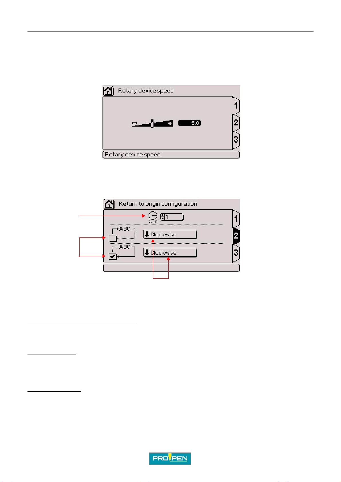
A"Edit file" menu
• Rotary device speed
TAB 1:
Used to determine the movement speed of the rotary device.
The screen below appears:
TAB 2:
Used to configurate the return to origin of the rotary device.
C
The screen below appears:
1
2
3
1 : Number of markings before return to origin 2 : Start/end file origin 3 : Return to origin type
Number of markings before return to orig in: Used to define after how many markings the rotary device returns to
origin. If the 1 value is selected, the rotary device returns t o ori gin after each marking.
Sta rt /end file origin:
file.
The origin at the end of a file is selected by default.
Used to define the moment the rotary device will r eturn to origi n in relati on to the marking of a
Return to origin type:
• clockwise
• counter-clockwise
• fast: shortest trave l di stance in relation to the current position
Ref. 92091 - P05_en_F
Used to choose the rotation direction of the rotary device to retur n to origin.
59/121
Page 60
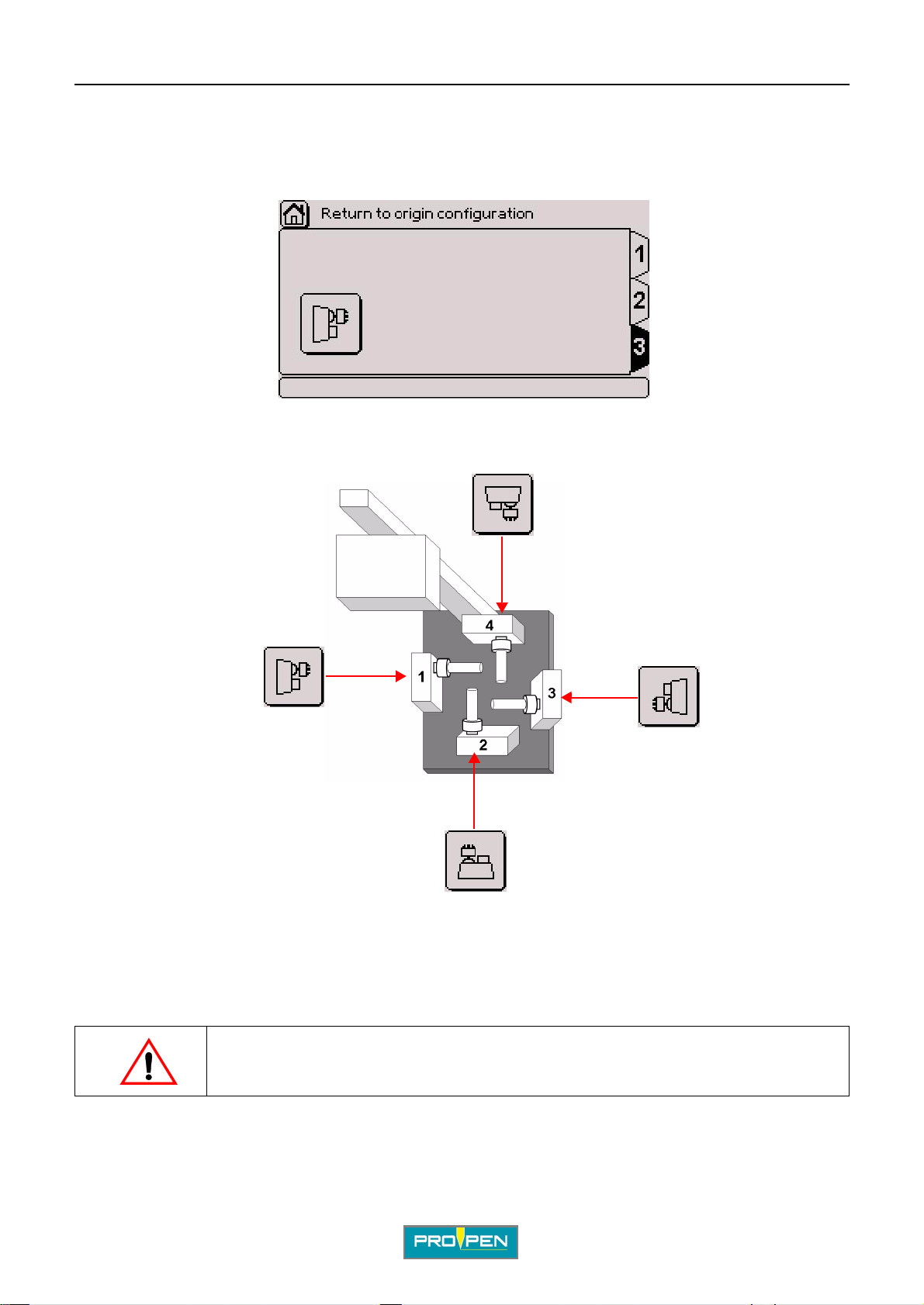
A"Edit file" menu
TAB 3:
Used to select the rotary device orientation in relation to the marking head.
The screen below appears:
Select the corresponding icon usi ng the arrows. Everytime the Enter key is pressed, the orientation is changed .
Examples
C
Head
1 : Rotary device on the X axis - motor to the left 2 : Rotary device on the Y axis - motor at the bottom 3 : Rotary device on the X axis - motor to the left 4 : Rotary device on the Y axis - motor at the top
Select rotary device orientation corresponding to its installation.
Ref. 92091 - P05_en_F
Correctly select the rotary device position: the conf iguration selection directly
influences the marking’s orientation on the part.
60/121
Page 61
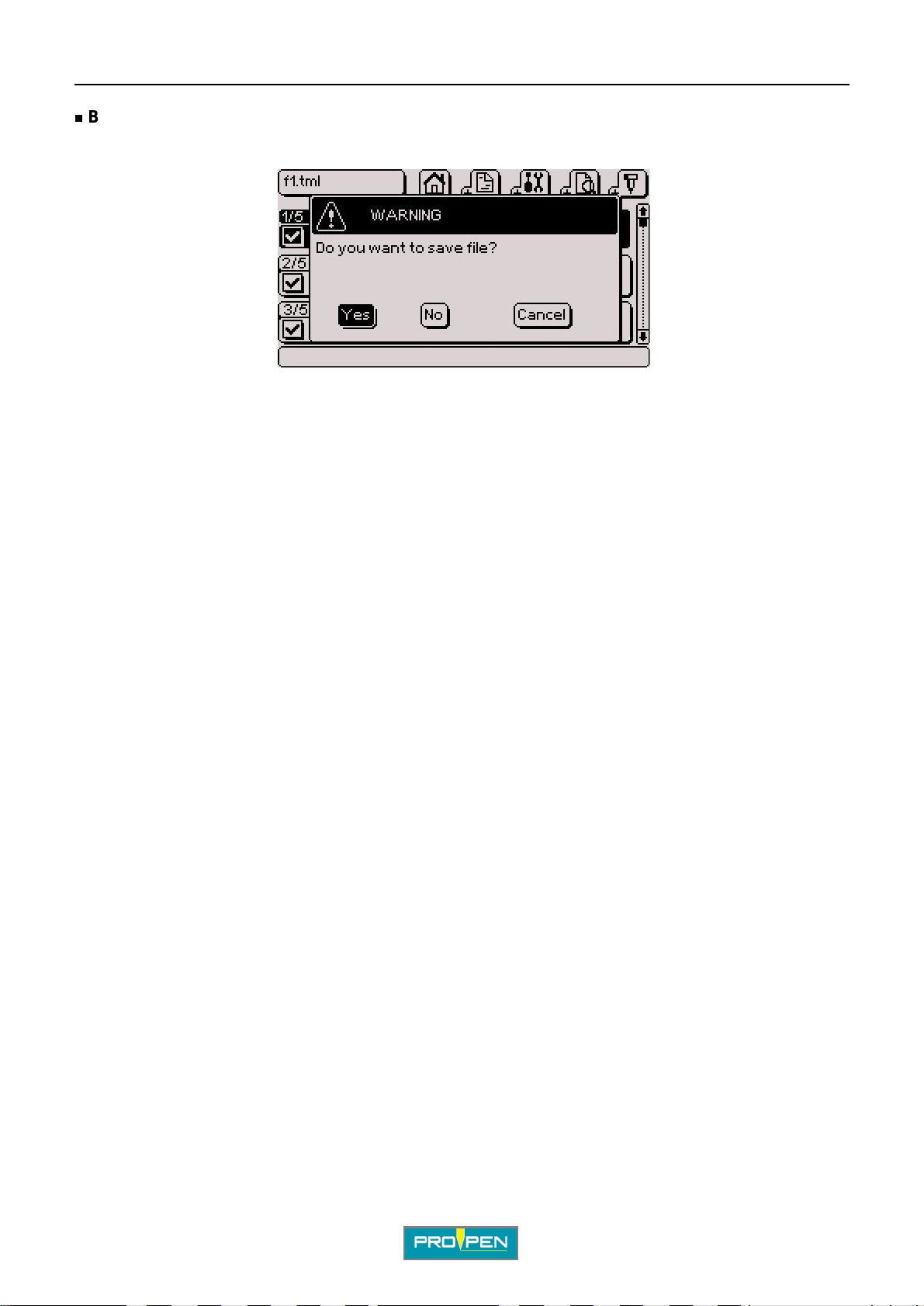
A"Edit file" menu
Back to the previous menu
If the file has not been saved, the program displays the following message:
Yes: Save selected file
No: Exit the file without saving
Cancel: Return to the marking file without valid ati ng modifications
C
Ref. 92091 - P05_en_F
61/121
Page 62
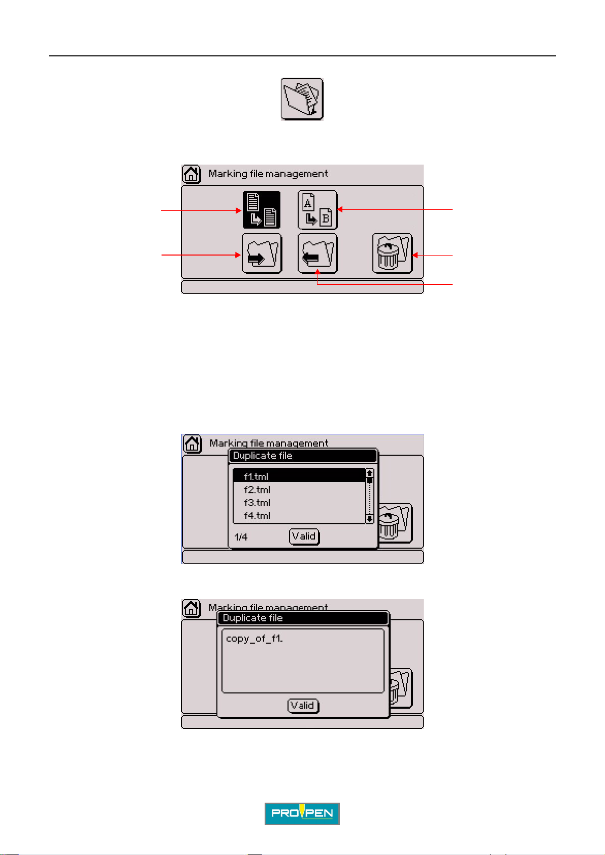
D"Marking file management" menu
Select this menu from the main menu, represented by the icon:
The screen below appears:
D
1
5
1 : Duplicate a file
2 : Rename a file
3 : Delete a file
4 : Export a file
5 : Import a file
1. Duplicate a file
Select the corresponding icon using the arrows. Validate by pressing Enter.
The screen below appears:
2
3
4
Select the file using the Up - Down arrows. Validate by pressing Enter. The screen below appears:
Rename the duplicated file as desi red. Validate by pressing Enter . The progra m disp lays a con firmatio n message.
Ref. 9209 1 - P05_en_F
62/121
Page 63
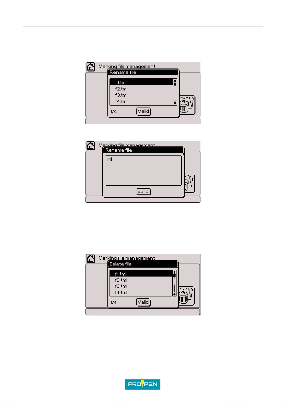
A"Marking file management" menu
2. Rename a file
Select the corresponding icon using the arrows. Validate by pressing Enter.
The screen below appears:
Select the file using the Up - Down arrows. Validate by pressing Enter. The screen below appears:
D
Rename the file as desired. Validate by pressing Enter. The program displays a confirmation message.
3. Delete a file
Select the corresponding icon using the arrows. Validate by pressing Enter.
The screen below appears:
Select the file using the Up - Down arrows. Validate by pressing Enter.
Ref. 92091 - P05_en_F
63/121
Page 64
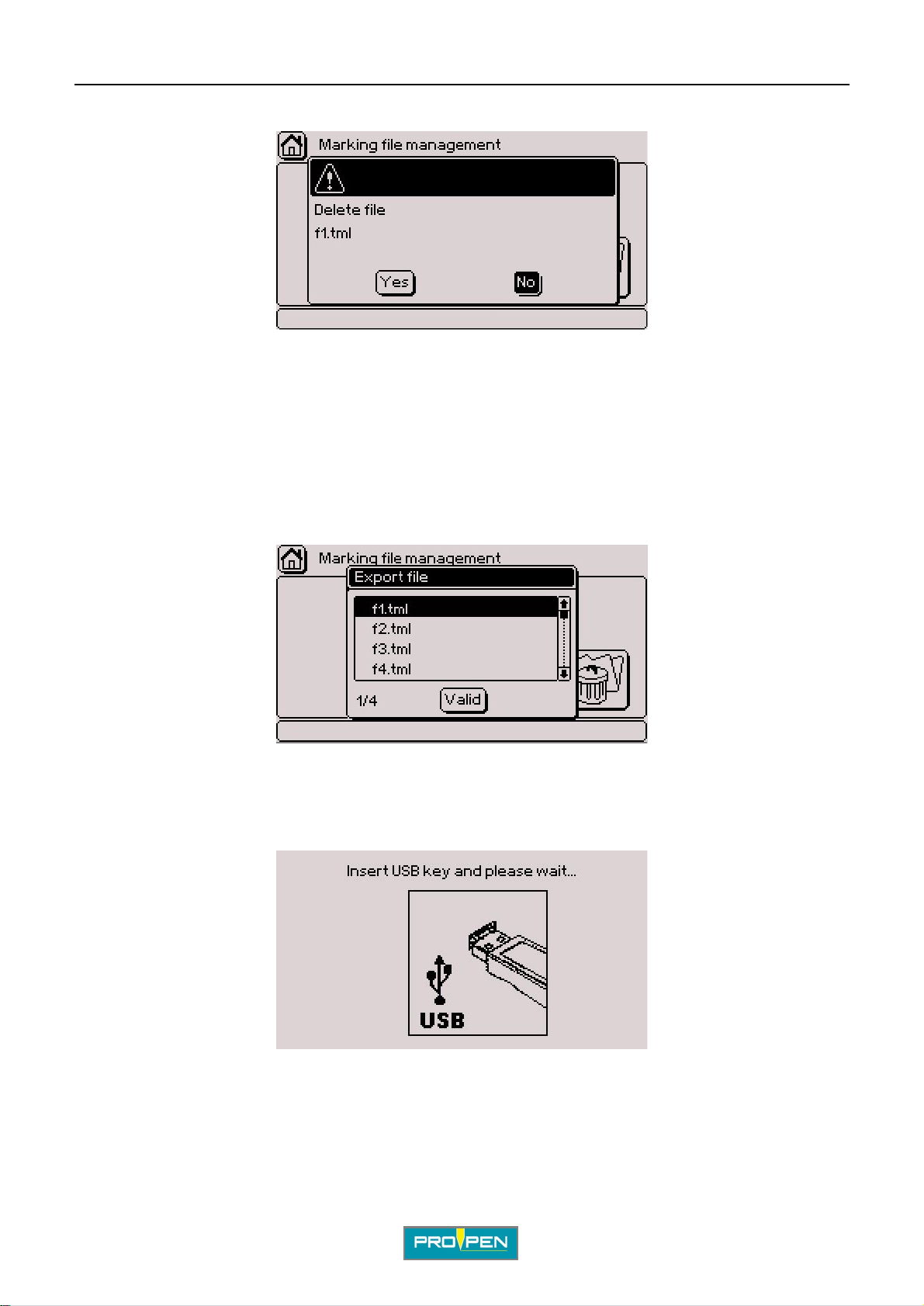
A"Marking file management" menu
The screen below appears:
Yes: Deleting the file - The program displays a confirmation message.
No: Return to the menu without deleting the file
4. Export a file
Used to export a file, to a PC or another marking machine for example, by downlo ading it onto a USB key.
Select the corresponding icon using the arrows. Validate by pressing Enter.
D
The screen below appears:
Select the file using the Up - Down arrows. Validate by pressing Enter.
To select several files, position on each desired file and press the Sp ace bar. Validate by pressi ng Enter.
To select all fil es, press the Ctrl + A keys on the keyboard. Validate by pre ssing Enter .
The screen below appears:
Insert a USB key into the USB port for download.
The program displays a confirmation message.
Ref. 92091 - P05_en_F
64/121
Page 65
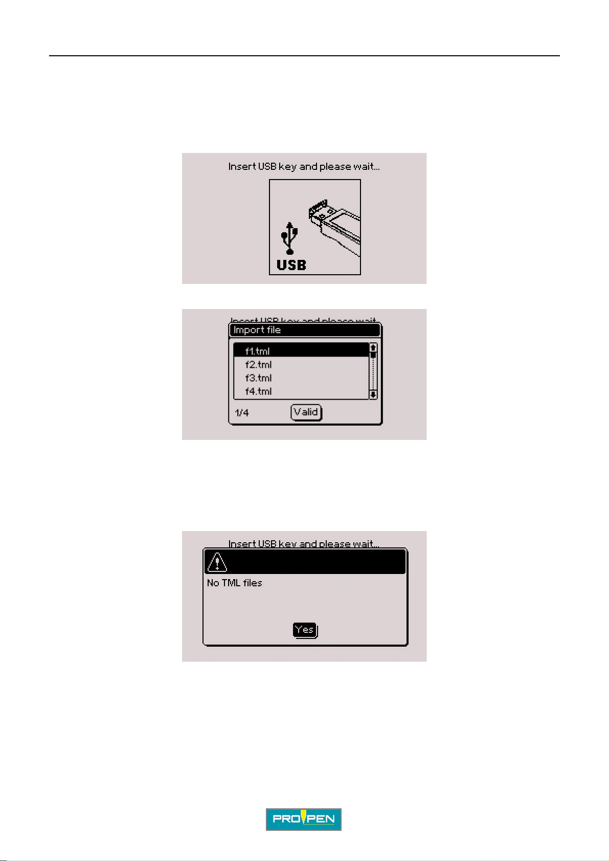
A"Marking file management" menu
5. Import a file
Used to import a file, from a PC or another marking machine for example, by downl oading it from a USB key.
Select the corresponding icon using the arrows. Validate by pressing Enter.
The screen below appears:
Insert a USB key into the USB port for download. The screen below appears:
D
Select the file using the Up - Down arrows. Validate by pressing Enter.
To select several files, position on each desired file and press the Sp ace bar. Validate by pressi ng Enter.
To select all fil es, press the Ctrl + A keys on the keyboard. Validate by pre ssing Enter .
The program displays a confirmation message.
If no file with the TML format is present, the following message is displayed:
V alidate by pres sing Enter . The pr ogram returns to the previous menu. Check the content of the key and try again.
Ref. 92091 - P05_en_F
65/121
Page 66
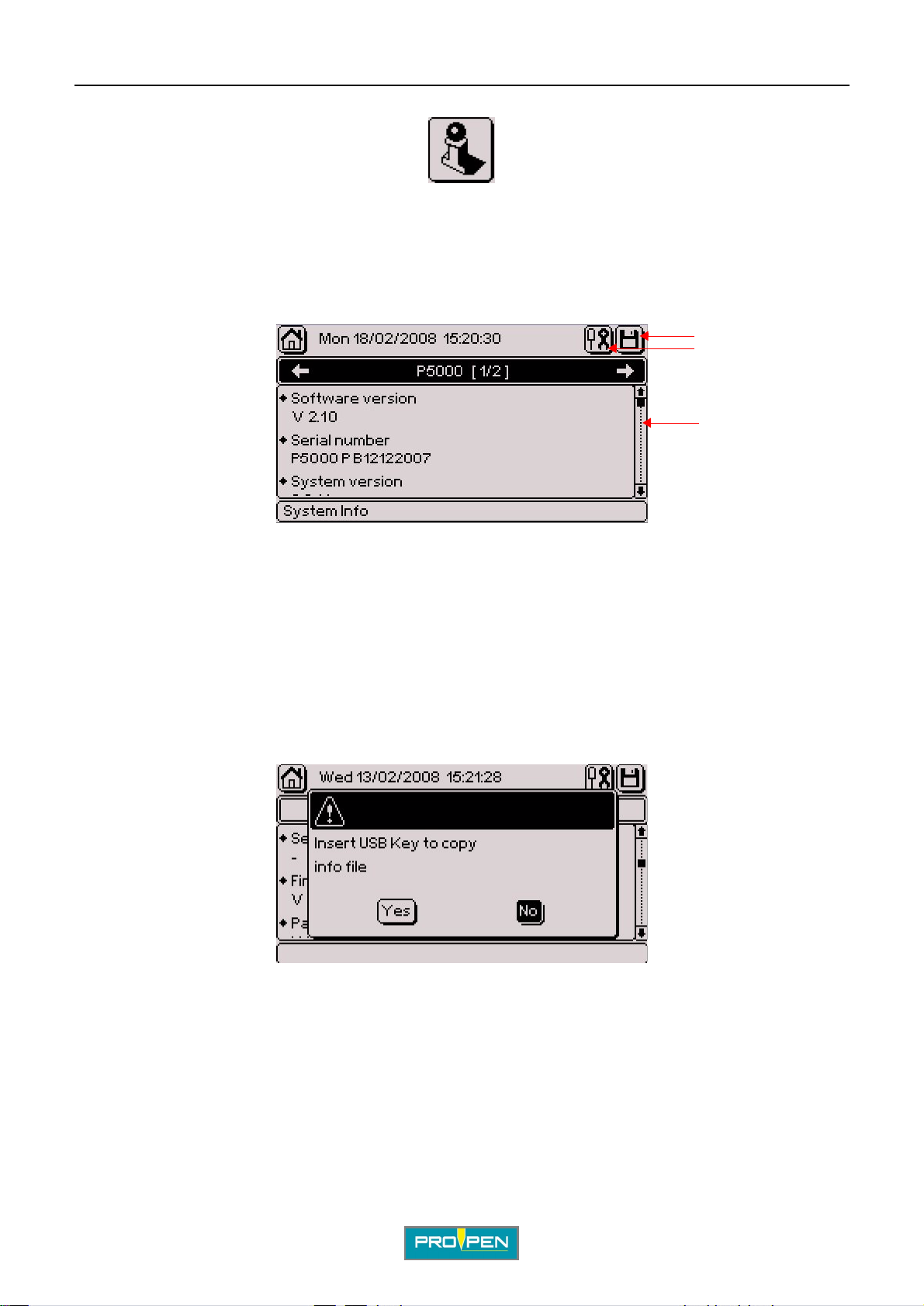
E"System info" menu
Select this menu from the main menu, represented by the icon:
This menu contains technical infor m ati on that can be communicated to the distributor or the techni cal support in
case of problem. It is made of several tabs, contain ing the character isti cs of the Control Unit , of the marking head
and of the eventual accessories installed.
1
2
3
E
1 : "Save" icon
2 : Maintenance
3 : Scroll bar
To go from one tab to another, use the Left - Right arrows of the keyboard.
To scroll thr ough the information, use the Up - Down arrows on the keyboard. To reach directly the beginning or
the end of the list, use the Home - End keys of the keyboard.
To access the icons at the top of the screen, press on the Context menu key of the keyboard.
To save this information on a USB key in order to communica te th em to the dis tr ibutor or the technical support,
select the "Save" icon using the arrows. The screen below appears:
No: Return to previous screen
Ref. 9209 1 - P05_en_F
66/121
Page 67
A"System info" menu
Yes: The screen below appears:
Insert a USB key into the USB port for download.
Maintenance
MENU UNDER CONSTRUCTION
E
Ref. 92091 - P05_en_F
67/121
Page 68
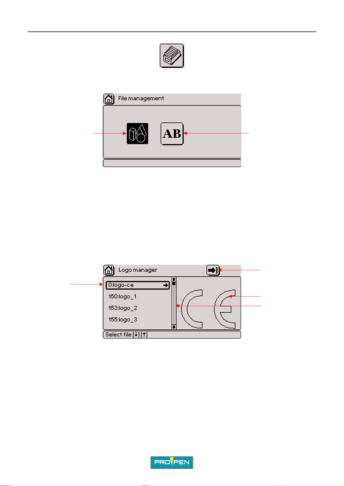
F"File management" menu
Select this menu from the main menu, represented by the icon:
The screen below appears:
12
1 : Logo management
2 : Font management
F
1. Logo management
This list indicates the available logos. Each logo is identified by a number. Logos are programmed in the CCU
board. The standard confi guration comes with 2 logo(s).
If other logos were ordered, they will also appear in this list.
Logos have the LO3 format.
The screen below appears:
2
1
3
4
1 : List of available logos
2 : Import a logo
3 : Preview of the selected logo
4 : Scroll bar
To exit the list of logos and access the "Import a logo" icon, press the Contex t menu key on the keyboard.
To scroll through the logos, use the Up - Down arrows on the keyboard. The corresponding logo is shown on the
right-hand side.
After selecting the desired logo, press the Right arrow on the keyboard to access the functions available for this
logo.
Ref. 9209 1 - P05_en_F
68/121
Page 69
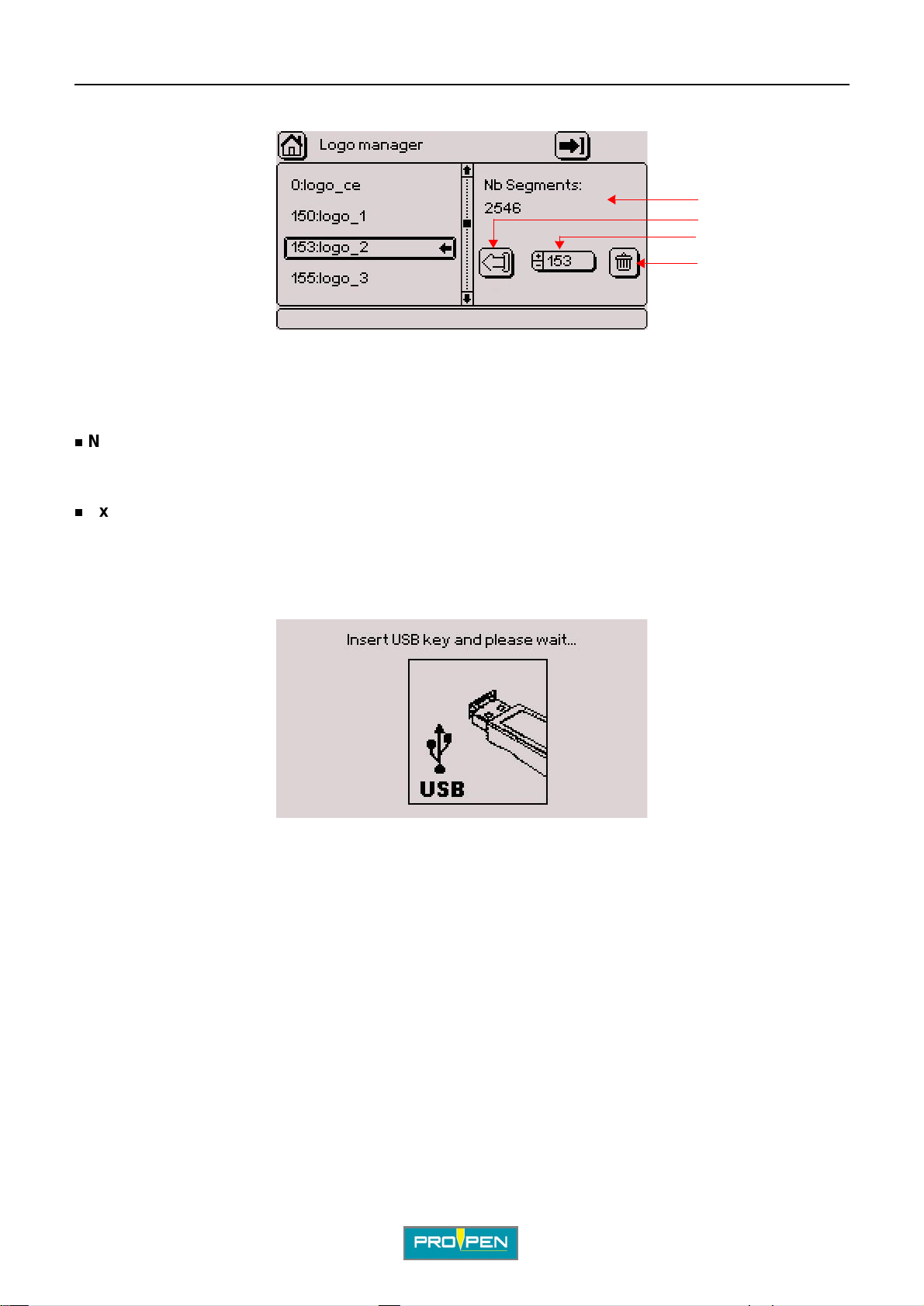
A"File management" menu
The screen below appears:
1 : Number of logo segments
2 : Export a logo
3 : Re-index a logo
4 : Delete a logo
Number of logo segments
Indicates the number of lines included in the vect or plotting of the logo.
Export a logo (LO3 format)
F
1
2
3
4
Used to export a logo, to a PC or another marking machine for example, by downloading it onto a USB key.
Select the corresponding icon using the arrows. Validate by pressing Enter.
The screen below appears:
Insert a USB key into the USB port for download.
The program displays a confirmation message.
Ref. 92091 - P05_en_F
69/121
Page 70
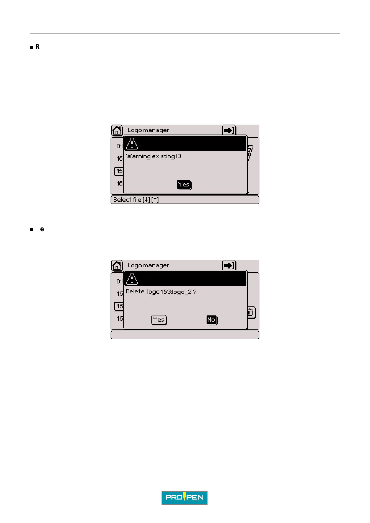
A"File management" menu
Re-index a logo
Used to change the number of a logo but not its name.
Select the corresponding icon using the arrows. Entry can be made either by:
• using the +/- keys on the numeric keypad
• pressing Enter then by typing the value directly on the keyboard
By returning to the list of logos using the Left arrow, the logo number is updated.
If the number given to the logo is already assigned, th e fol lowi ng message is displayed:
F
The logo keeps its current number. Try again by assigning a number that is not already used.
Delete a logo
Select the corresponding icon using the arrows. Validate by pressing Enter.
The screen below appears:
Yes: Deleting the logo
No: Return to the previous screen without deleti ng the l ogo
Cancel: Return to the previous screen without deleting the logo
Note
The standard configuration logos bear a number between 0 and 99. The additional logos bear a number starting
from 100.
The standard configuration logos cannot be exported, re-indexed nor deleted. No function regarding these logos
is available.
Ref. 92091 - P05_en_F
70/121
Page 71
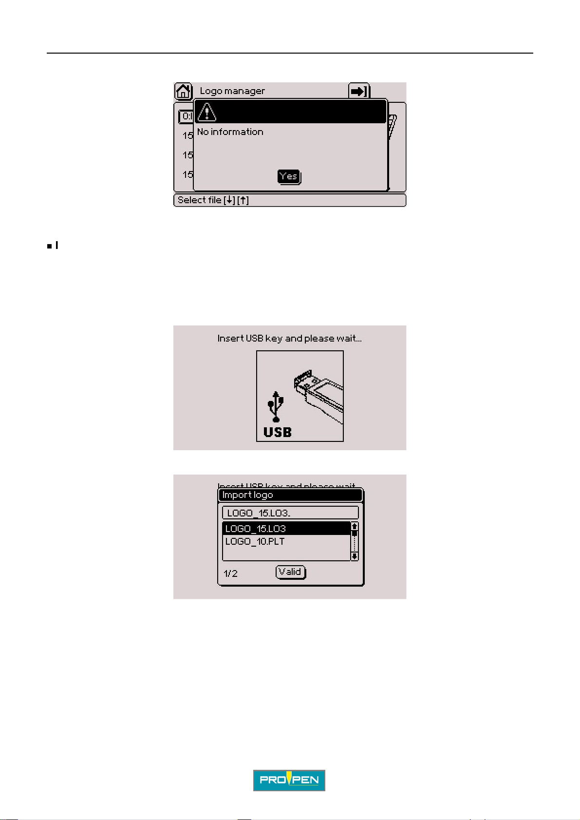
A"File management" menu
In this case, when pressing the Right arrow, the screen below is shown:
Only the additional logos can be modified.
Import a logo
Used to import a logo, from a PC or another marking machine for example, by downloading it from a USB key.
To exit the list of logos and access the "Import a logo" icon, press the Context menu key on the keyboard. Select
the arrow in the top right corner of the screen. Validate by pressing Enter.
The screen below appears:
F
Insert a USB key into the USB port for download. The screen below appears:
Select the logo using the Up - Down arrows. Validate by pressing Enter.
To select several files, position on each desired file and press the Sp ace bar. Validate by pressi ng Enter.
To select all fil es, press the Ctrl + A keys on the keyboard. Validate by pre ssing Enter .
The program displays a confirmation message.
By default, number 255 is assigned to the imported logo. If several logos are imported, this val ue decrements
(254, etc..).
Ref. 92091 - P05_en_F
71/121
Page 72
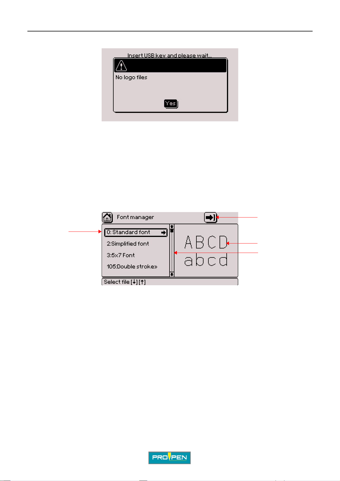
A"File management" menu
If no file with the LO3 - PLT format is present, the following message is displ ayed:
V alidat e by pressi ng Enter. The program returns in the pr evious p age. Ch eck the conte nt of the key and try again.
2. Font man a gement
This list indicates the fonts available in memory. Each font is identified by a number. Character fonts are
programmed in the CCU board. The standard configuration comes with 3 fonts (pneumatic version).
If other fonts were ordered, they will also appear in this list.
F
Fonts have the PO3 format.
The screen below appears:
2
1
3
4
1 : List of available fonts
2 : Import a font
3 : Preview of the selected font
4 : Scroll bar
To exit the list of fonts and access the "Import a font" icon, press the Context menu key on the keyboard.
To scroll through the fonts, use the Up - Down arrows on the keyboard. The corresponding font is shown on the
right-hand side.
After selecting the desired font, press the Right arrow on the keyboard to access the functions available for this
font.
Ref. 92091 - P05_en_F
72/121
Page 73
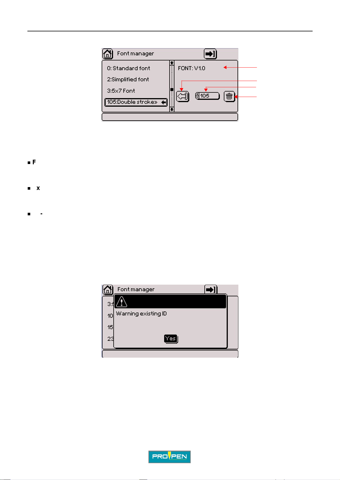
A"File management" menu
The screen below appears:
1 : Font version
2 : Export a font
3 : Re-index a font
4 : Delete a font
Font version
Indicates the version of the font selected.
Export a font (PO3 format)
F
1
2
3
4
MENU UNDER CONSTRUCTION
Re-index a font
Used to change the number of a font but not its name.
Select the corresponding icon using the arrows. Entry can be made either by:
• using the +/- keys on the numeric keypad
• pressing Enter then by typing the value directly on the keyboard
By returning to the list of fonts using the Left arrow, the font number is updated.
If the number given to the font is already assigned, the following message is displayed:
The font keeps its current number. Try again by assigning a number that is not already used.
Ref. 92091 - P05_en_F
73/121
Page 74
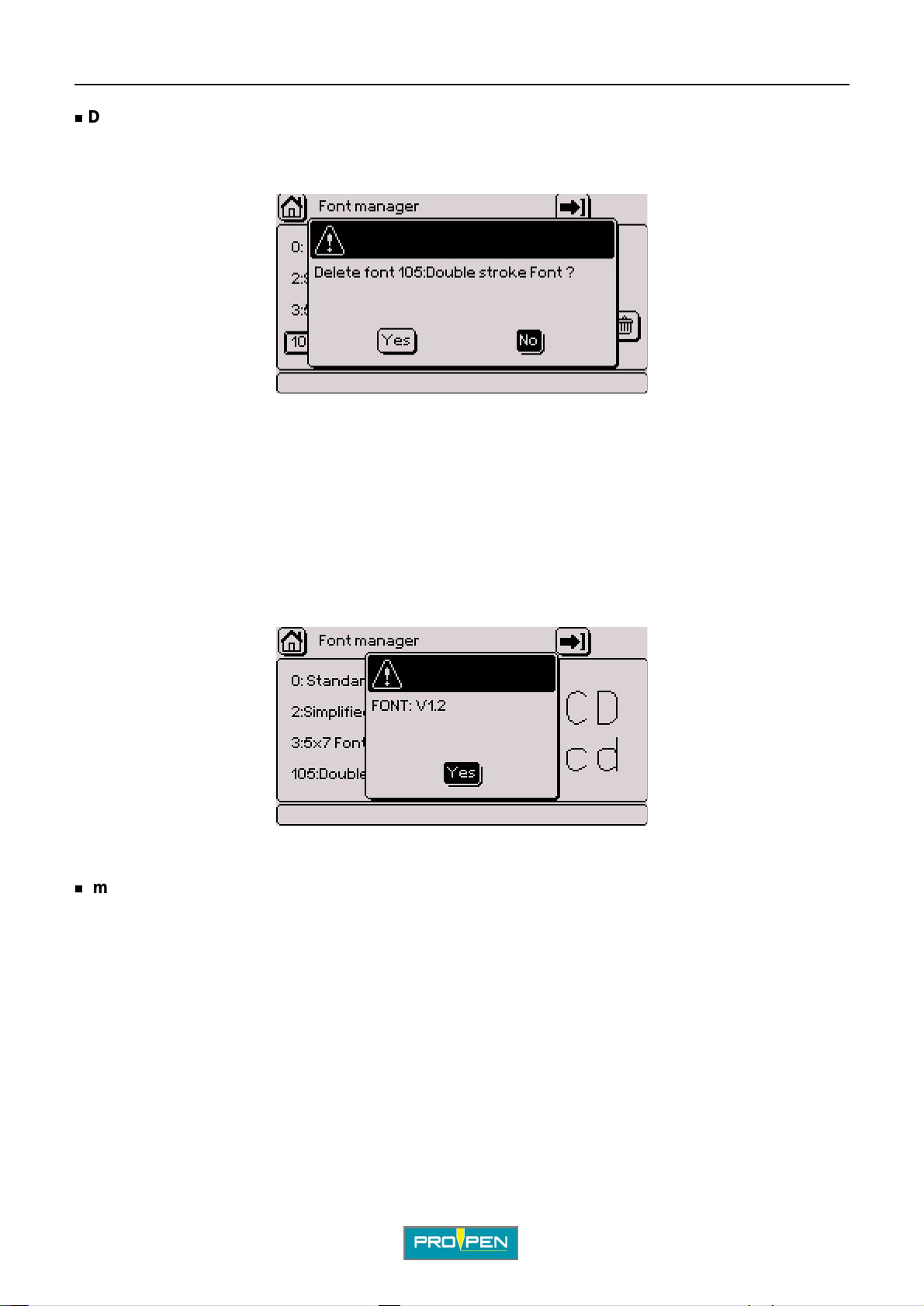
A"File management" menu
Delete a font
Select the corresponding icon using the arrows. Validate by pressing Enter.
The screen below appears:
Yes: Deleting the font
No: Return to the previous screen without deleti ng the f ont
Cancel: Return to the previous screen without deleting the font
Note
The standard configuration fonts bear a number between 0 and 99. The additional fonts bear a number starting
from 100.
F
The standard configur ation f onts can not be export ed, re-indexed nor dele ted. No functi on reg arding t hese font s is
available. Only the font’s version is indicated.
In this case, when pressing the Right arrow, the screen below is shown:
Only the additional fonts can be modified.
Import a font
Used to import a font, from a PC or another marking machine for example, by downloading it from a USB key.
To exit the list of fonts and access the "Import a font" icon, press the Context menu key on the keyboard. Select
the arrow in the top right corner of the screen. Validate by pressing Enter.
Ref. 92091 - P05_en_F
74/121
Page 75
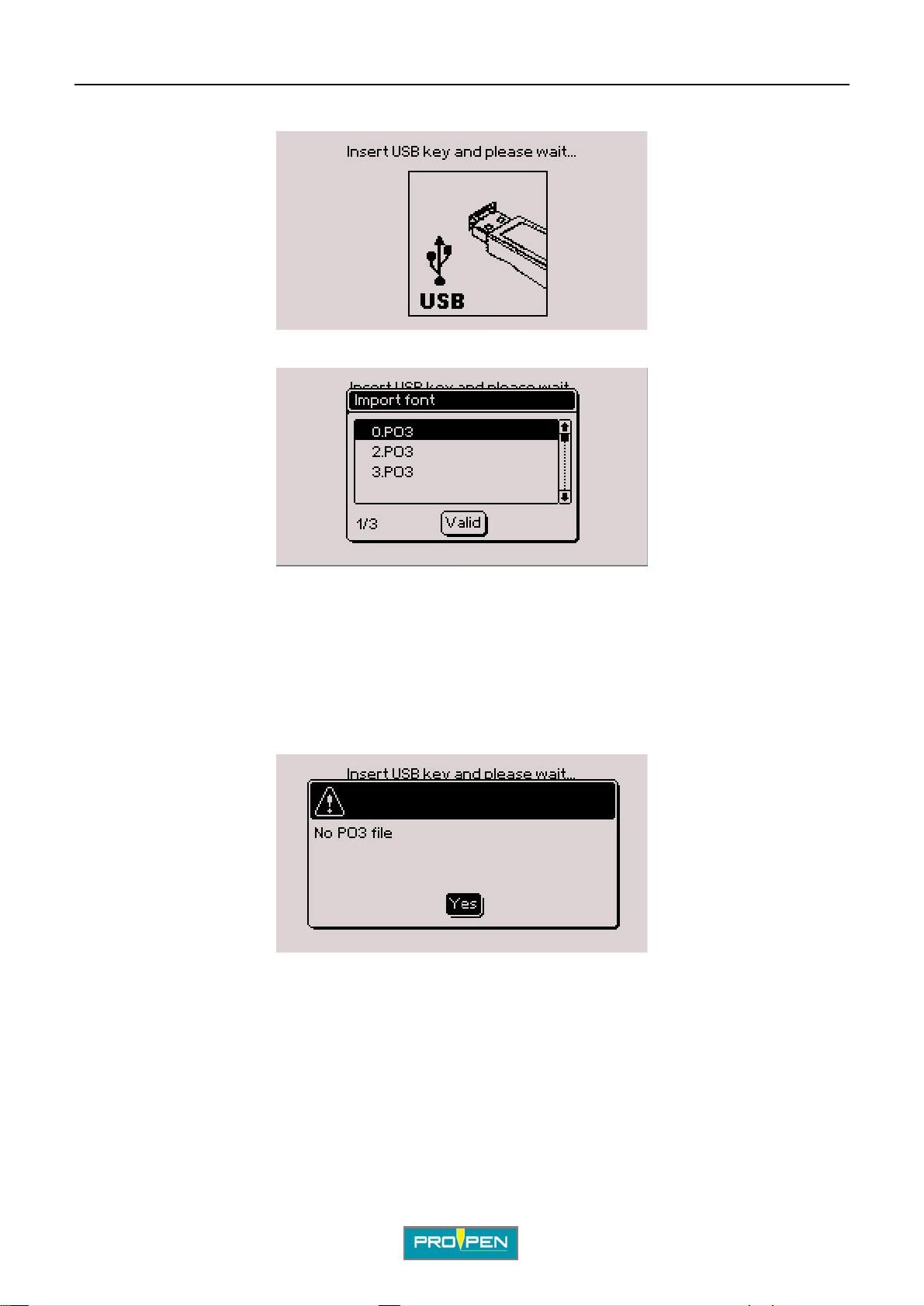
A"File management" menu
The screen below appears:
Insert a USB key into the USB port for download. The screen below appears:
F
Select the font using the Up - Down arrows. Validate by pressing Enter.
To select several files, position on each desired file and press the Sp ace bar. Validate by pressi ng Enter.
To select all fil es, press the Ctrl + A keys on the keyboard. Validate by pre ssing Enter .
The program displays a confirmation message.
By default, number 255 is assi gned to t he import ed font. If severa l f onts ar e import ed, t his value decrement s (2 54,
etc...).
If no file with the PO3 format is present, the following message is displayed:
V alidat e by pressi ng Enter. The program returns in the pr evious p age. Ch eck the conte nt of the key and try again.
Ref. 92091 - P05_en_F
75/121
Page 76
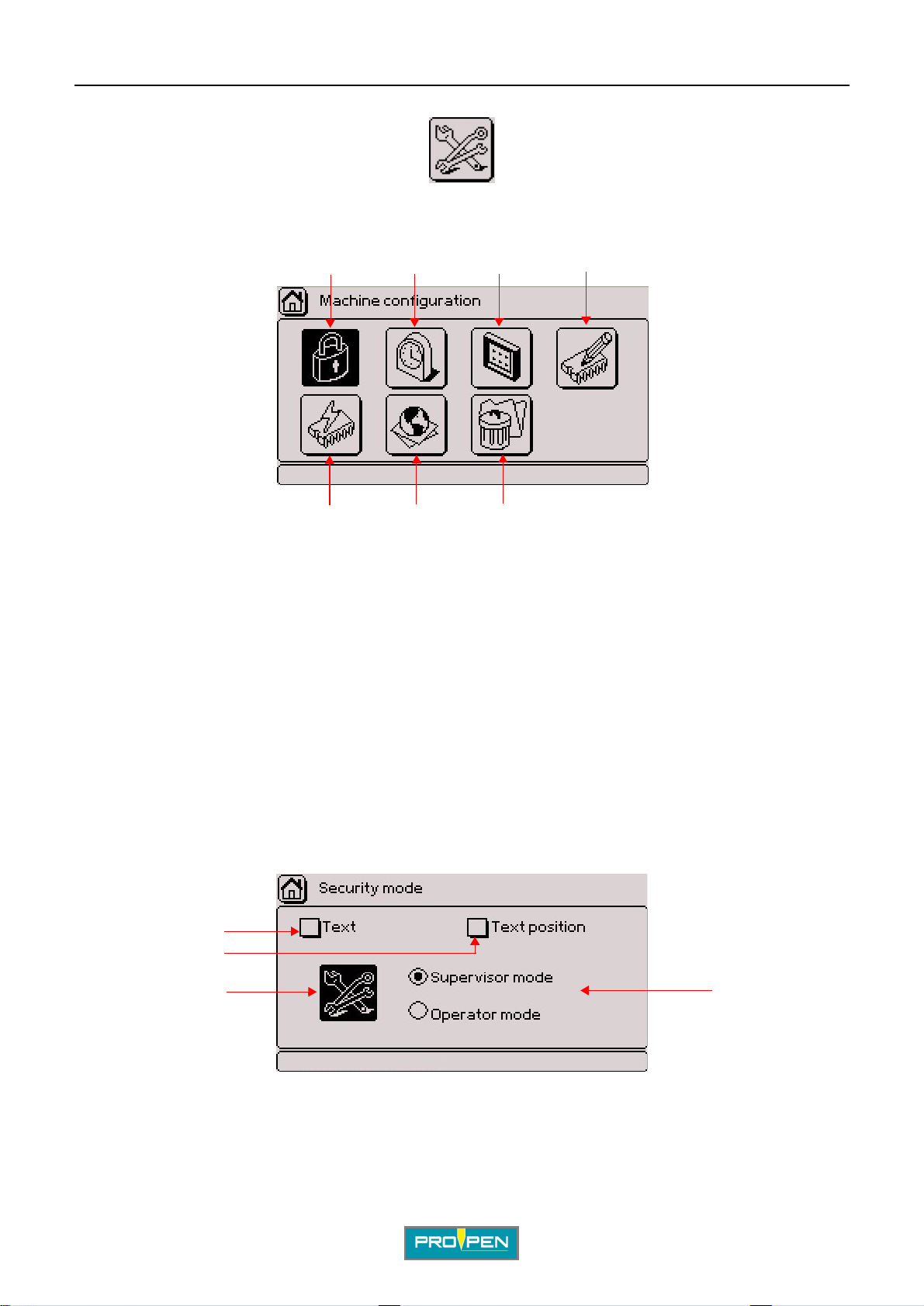
G"Machine configuration" menu
Select this menu from the main menu, represented by the icon:
The screen below appears:
12 4
3
G
5
1 : Security mode
2 : Time and date settings
3 : Display settings
4 : Machine parameters
5 : Deleting all the files (reset)
6 : Language
7 : Update
7
6
1. Security mode
Used to:
• change the password.
• select either "Supervisor" or "Operator" mode for the operating mode of the program.
• define the modifiable parameters in "Operator" mode.
The screen below appears:
1
2
1 : Modifiable parameters in "Operator" mode
2 : Setting the password
3 : Operating mode
Ref. 9209 1 - P05_en_F
3
76/121
Page 77
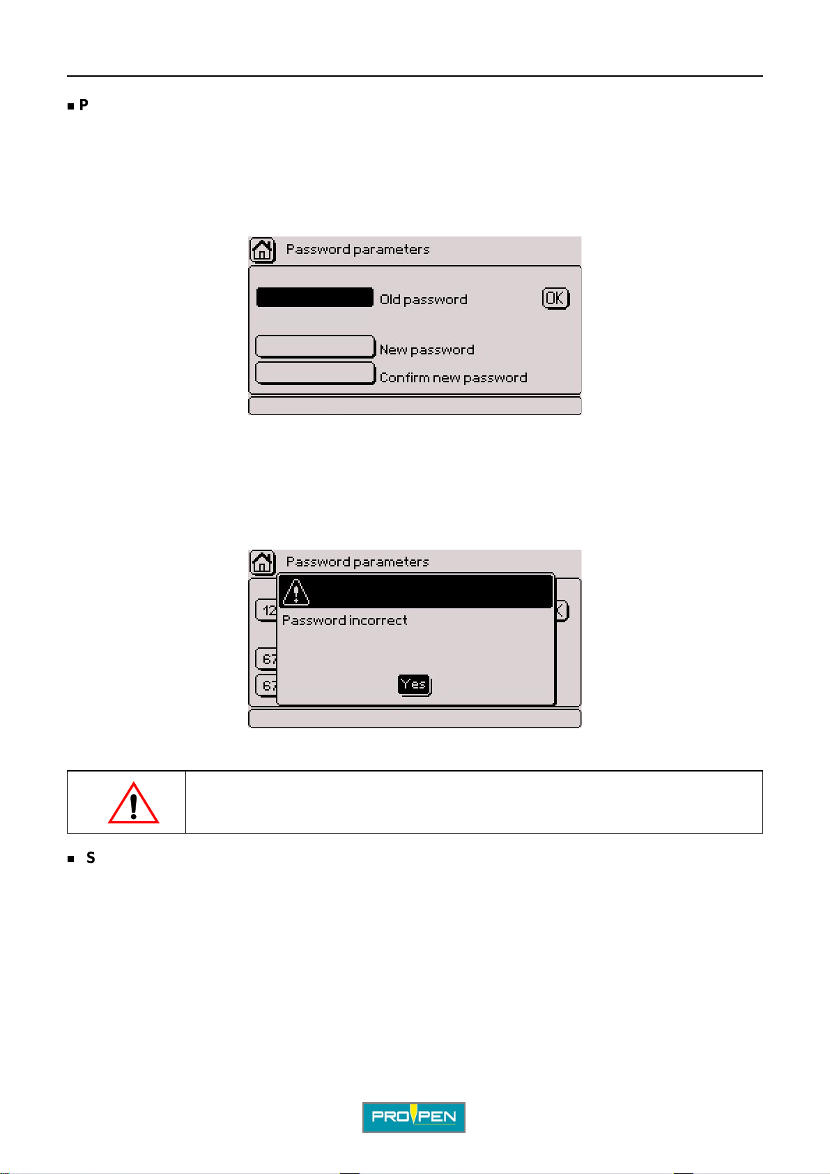
A"Machine configuration" menu
Password
Switching from "Operator" mode to "Supervi sor" mode is protected by a password. The password configured by
default is 12345. This password can only be changed under the "Supervisor" operating mode. It may contain a
maximum of 8 alphanumeric characters.
To change the password, select the password configuration icon.
The screen below appears:
Press Enter to access the entry fiel d. Ente r the current password. Validate by pressing Enter.
G
Enter the new password. For confirmation, enter the new password again.
The cursor is positioned on the "OK" button. Validate by pressing Enter .
This message warns that an incorrect password was entered. The cursor is posi ti oned on the "Yes" button.
Validate by pressing Enter. The program returns to the main menu. Re-ent er the password.
Switching from "Supervisor" mode to "Operator" mode is not protected by a
password. Obtain the password before switching mode.
"Supervisor" mode
Used to:
• access to all functions in the progr am.
• select the functions authorized in the "Operator" operating mode.
Position the cursor on this operating mode using the arrow keys and press Enter to select it.
Ref. 92091 - P05_en_F
77/121
Page 78
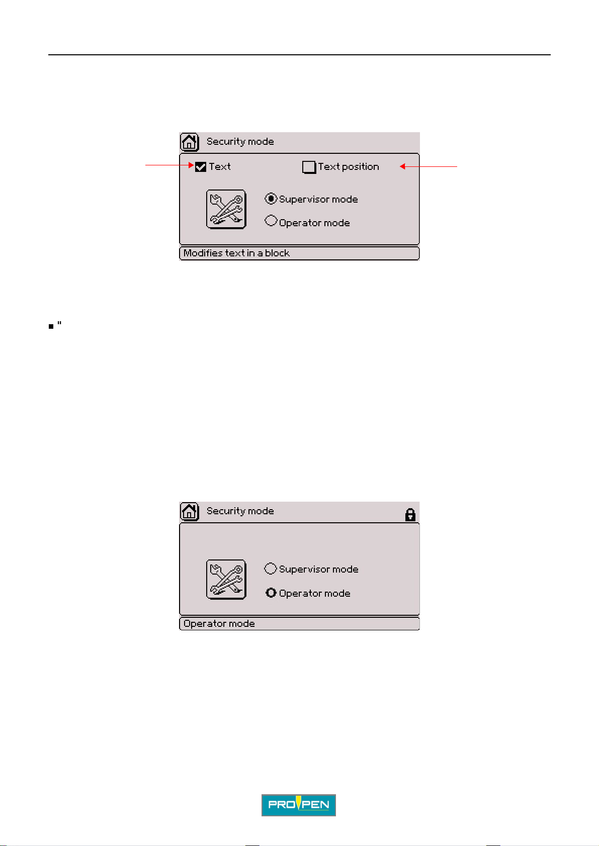
A"Machine configuration" menu
Select the functions authorized in the "Operator" operating mode using the arrow keys. Validate by pressing
Enter.
• Text: checking off the box means the "Text" field of a block can be modified.
• Text position: checking off the box means the X-Y coordinates of the text of a block can be modified.
12
1 : Activated parameter
2 : Deactivated parameter
If no parameter is activated, it is not possible to modify or save the marking files in "Operator " mo de.
"Operator" mode
G
Functions accessible in "Operator" mode:
• "Marking" menu
• open the last file used.
• open an existing file.
• modification of the "Text" field of a block (if authorized)
• modification of the X-Y coordinates of the text of a block (if authorized)
• stylus movement (F3)
• "System info" menu
• security mode ("Machine configuration" menu)
In "Operator" mode, a padlock is displayed in the top right corner of the screen:
Ref. 92091 - P05_en_F
78/121
Page 79
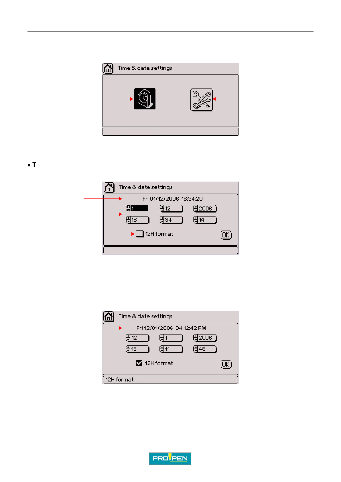
A"Machine configuration" menu
2. Time and date settings
12
1 : Time and date settings
2 : Setting the clock
Time and date settings
Used to set the machine’s internal clock. The screen below appears:
G
1
2
3
1 : Current time and date
2 : Time and date modification fields
3 : Viewing time in 12h format
To modify the time or date, use the +/- keys on the numer ic keypad.
Viewing time in 12h format: Use the Up - Down ar rows to select thi s parameter. To acti vate the corre sponding box,
press Enter.
1
1 : Current time and date - 12h format (AM/PM)
Ref. 92091 - P05_en_F
79/121
Page 80
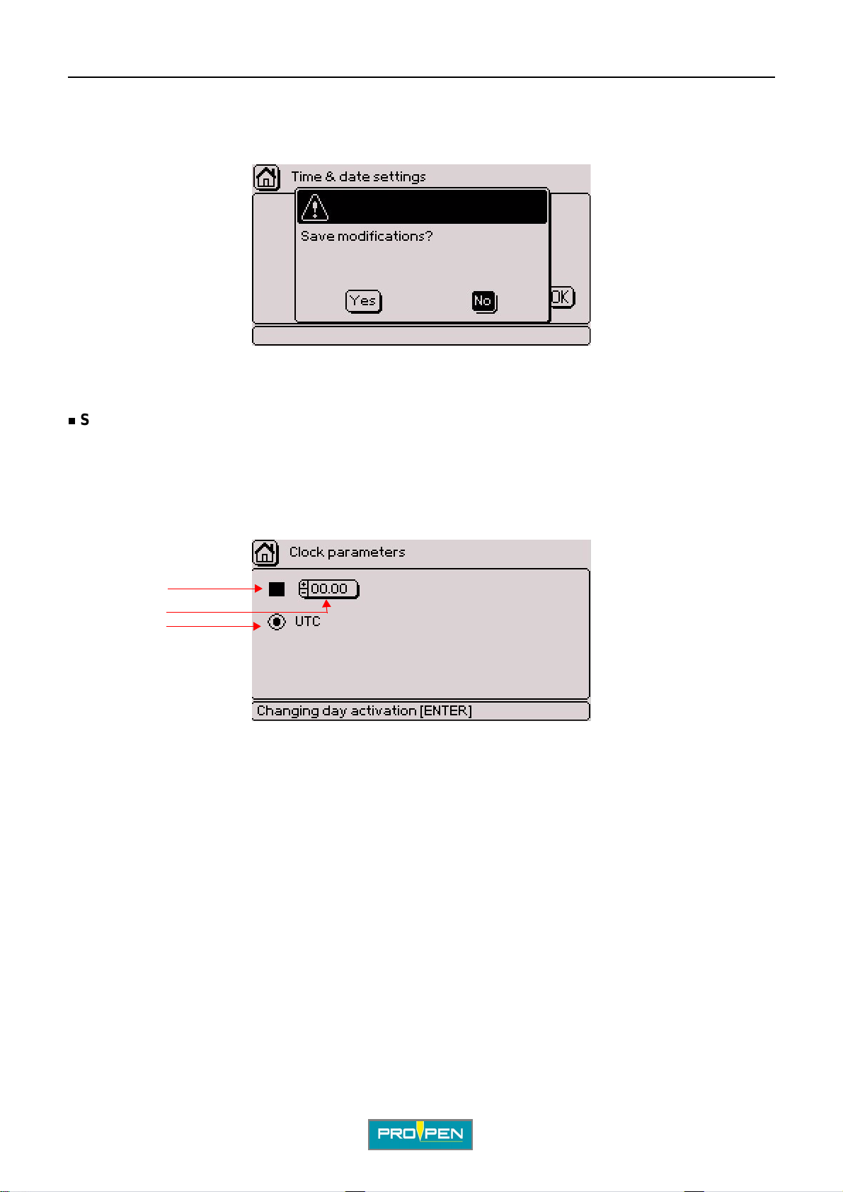
A"Machine configuration" menu
To save the selected p arameters, select the "OK" button in the lower right corne r using the arrow keys. Validate by
pressing Enter.
The screen below appears:
Yes: Back to the previous screen after saving the parameters No: Return to previous screen
Setting the clock
Used to:
G
• select the time for the change of day of the year (key word CCC)
• determine the time when the daylight saving ti me will be changed.
The screen below appears:
1
2
3
1 : Activation of the change of day
2 : Time of change of day
3 : Universal time
Activation of the change of day
To activate or deact ivate this function, position the cursor on the corresponding box. Validate by pressing Enter.
Go to the "Time" field using t he arrows. Select the time at which the number of the day in the year incre ases.
Entry can be made either by:
• using the +/- keys on the numeric keypad
• pressing Enter then by typing the value directly on the keyboard
Universal time
When the box is ticked, there is no change when the daylight saving time changes.
Ref. 92091 - P05_en_F
80/121
Page 81
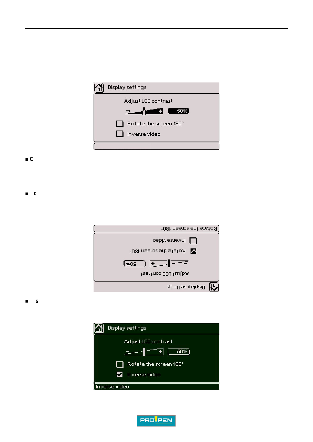
A"Machine configuration" menu
3. Display settings
Used to:
• adjust the contrast of the screen.
• rotate the screen by 180°.
• view the screen in reverse video.
Contrast
To adjust the contrast, use the +/- keys on the numeric keypad. Shortcut: Ctrl + Alt + A/Q.
G
This value is expressed as a percent. The default value is 50%.
Screen rotated 180°
Some applications require a 180° screen rotation.
Use the Up - Down arrows to s elect this parameter. To activate the corresponding box, press Enter. Shortcut: Ctrl
+ Alt + F.
Display in reverse video
View of the screen in reverse video: Use the Up - Down arrows to select this parameter. To activate the
corresponding box, press Enter. Shortcut: Ctrl + Alt + I.
Ref. 92091 - P05_en_F
81/121
Page 82
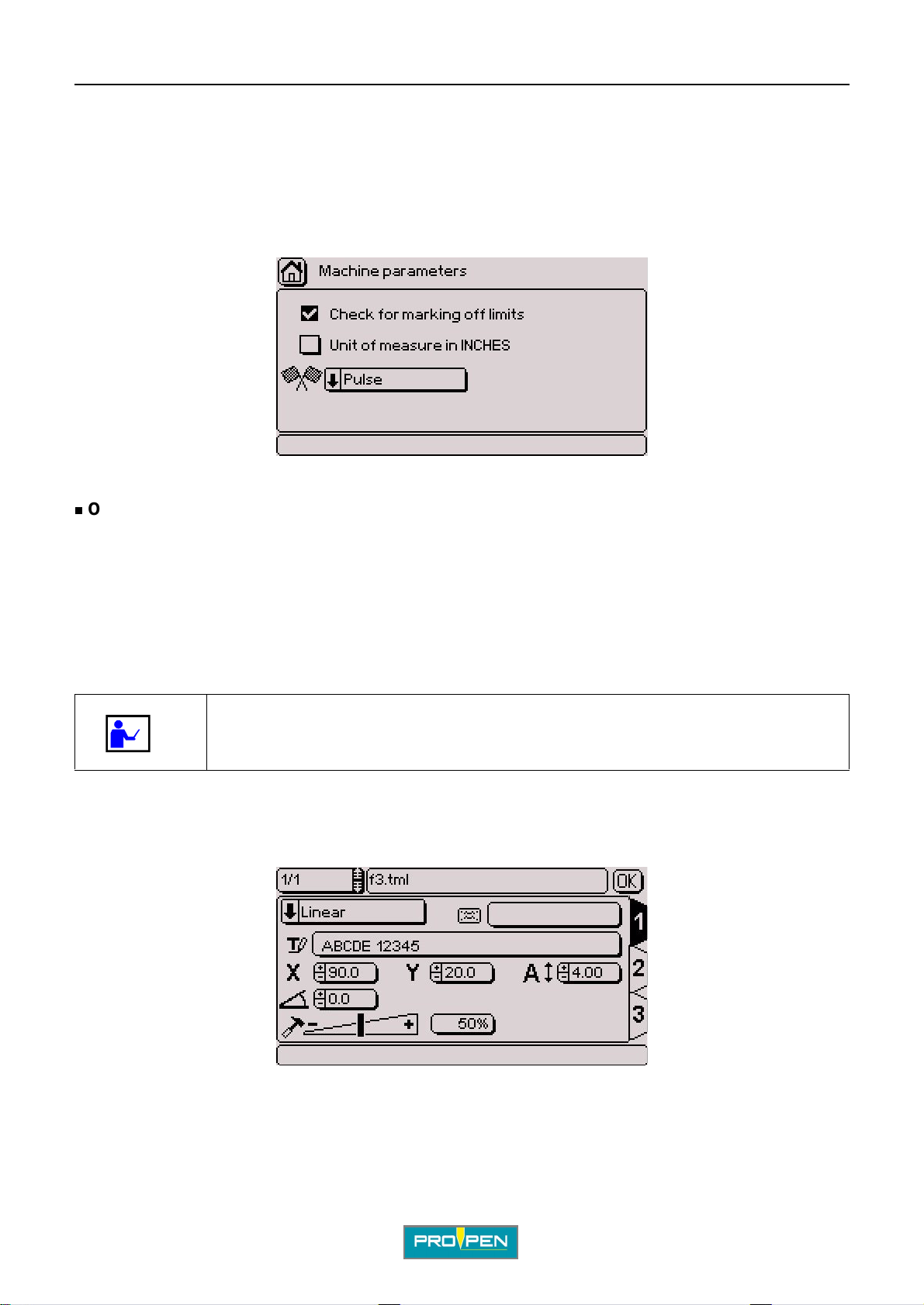
A"Machine configuration" menu
4. Machine parameters
Used to:
• select the "Off-l imits control" opti on.
• convert the units into inches.
• select the type of marking end.
Off-limits control
G
This option is activated by default.
If the marking is off-limit s, the program sends an error message.
The calculation time is extended and the total cycle time is longer.
When the off-l imits cont rol is deac tivat ed, the s tylus may run i nto th e mecha nical stop i f t he text is too long or if t he
coordinates are incorrect. However, calculation of the marking coordinates is faster, therefore the total cycle time
is shorter .
Use the off-limits control when preparing or updating a marking file, then deactivate this option.
Example of an off-limit marking along X:
Marking file
Ref. 92091 - P05_en_F
82/121
Page 83
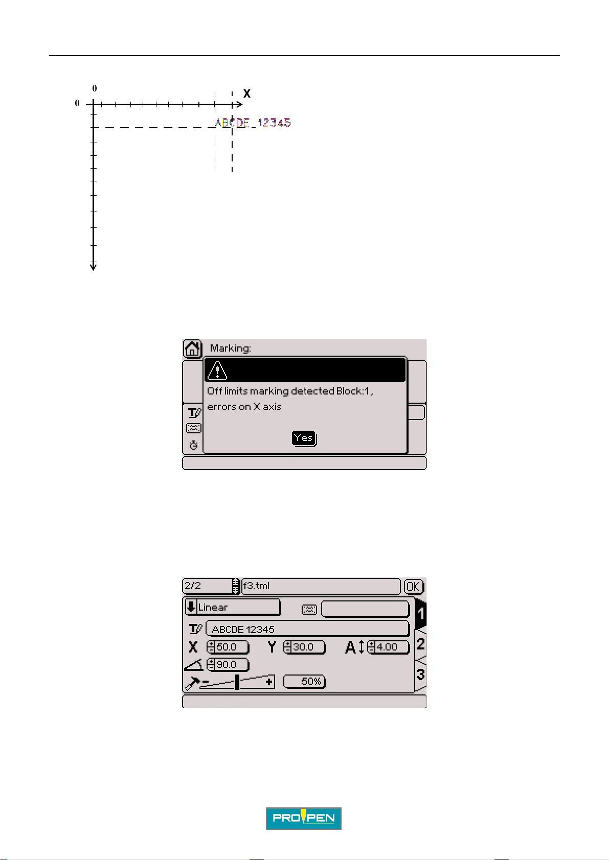
A"Machine configuration" menu
G
0
0
Y
Error message
X
Travel distance of the machine: X = 100 mm (3.937 in) Y = 110 mm (4.331 in)
Coordinates of the text to be marked: X = 90 mm (3.543 in) Y = 20 mm (0.787 in)
Character size: 4 mm (0.157 in)
The cursor is positioned on the "Yes" button. Validate by pressing Enter. Marking is cancelled.
For this example, change the X value, the character size, or reduce the text to be marked.
Example of an off-limit marking along Y:
Marking file
Ref. 92091 - P05_en_F
83/121
Page 84
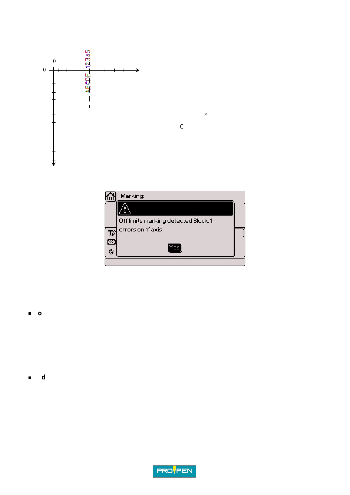
A"Machine configuration" menu
G
0
0
Y
Error message
X
Travel distance of the machine: X = 100 mm (3.937 in) Y = 110 mm (4.331 in)
Coordinates of the text to be marked: X = 50 mm (1.969 in) Y = 30 mm (1.181 in) Angle : 90
Character size: 4 mm (0.157 in)
°
The cursor is positioned on the "Yes" button. Validate by pressing Enter. Marking is cancelled.
For this example, change the Y value, or the charact er size.
Conversion of the units into inches
The marking program works in both millimeters and inches . All values pertaining to length are expressed in the
chosen unit. To switch from millimeters to inches, position the cursor on the corresponding box. Validate by
pressing Enter.
Changing from mm to inches automatically converts all values contained in the marking files.
End marking type
Used to select the communication signals duri ng marking.
3 modes are available:
• in-process mode
• maintained mode
• pulse mode
Ref. 92091 - P05_en_F
84/121
Page 85
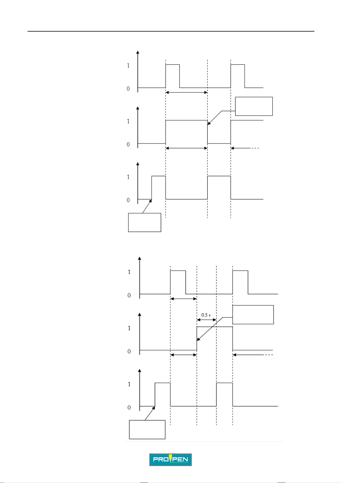
• In-process mode:
Impulse
Start cycle
A"Machine configuration" menu
G
Information
Marking in progress
Ready to marking
• Maintained mode:
Impulse
Start cycle
File loaded
Marking
Marking
End of marking
cycle
Marking
Marking in progress
Ready to marking
Ref. 92091 - P05_en_F
Information
File loaded
Marking
Marking
End of marking
cycle
Marking
85/121
Page 86
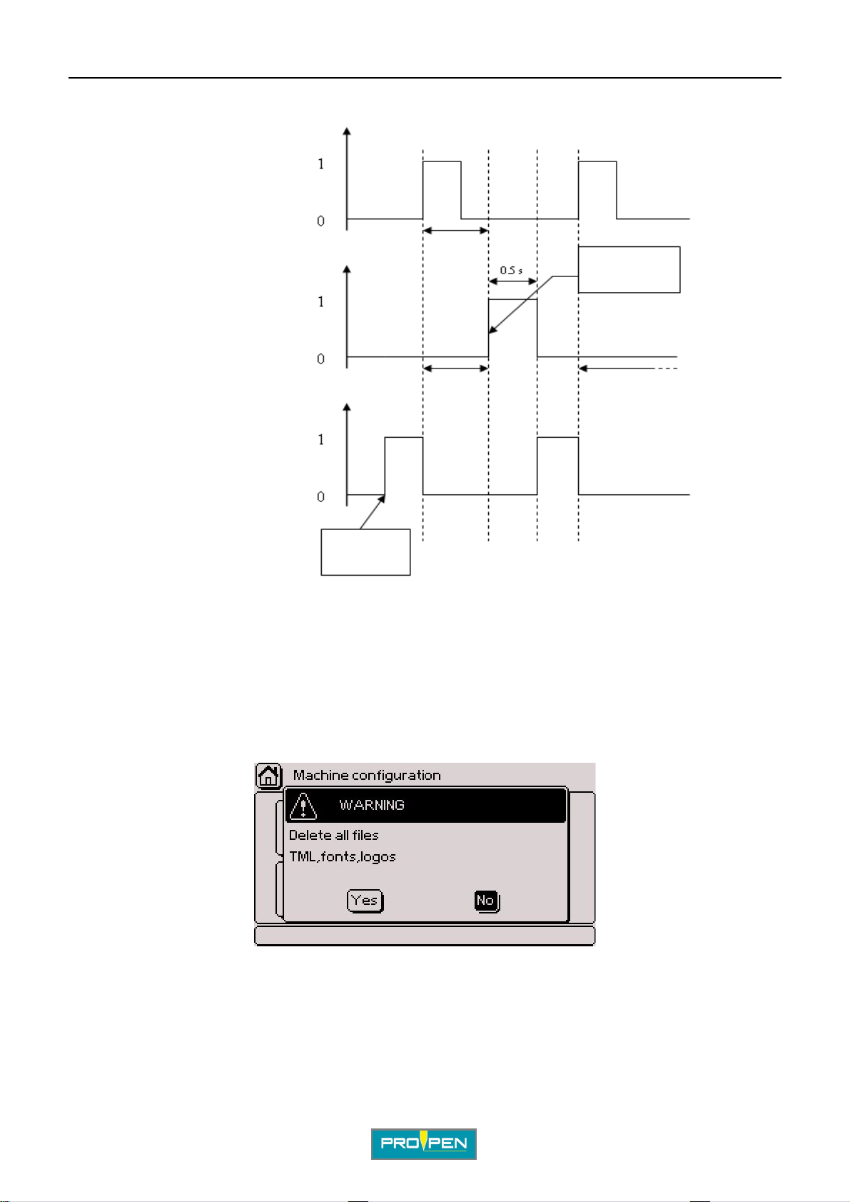
• Pulse mode:
A"Machine configuration" menu
G
Impulse
Start cycle
Marking
Information
Marking in progress
Marking
Ready to marking
File loaded
Note
To use TAG3500, the pulse mode must always be selected.
End of marking
cycle
Marking
5. Deleting all the files (reset)
Used to delete the saved files all at once: marking files, fonts, logos. ..
Select the corresponding icon using the arrows. Validate by pressing Enter. The screen below appears:
Yes: Deleting all the files (reset) No: Return to previous screen
Ref. 92091 - P05_en_F
86/121
Page 87
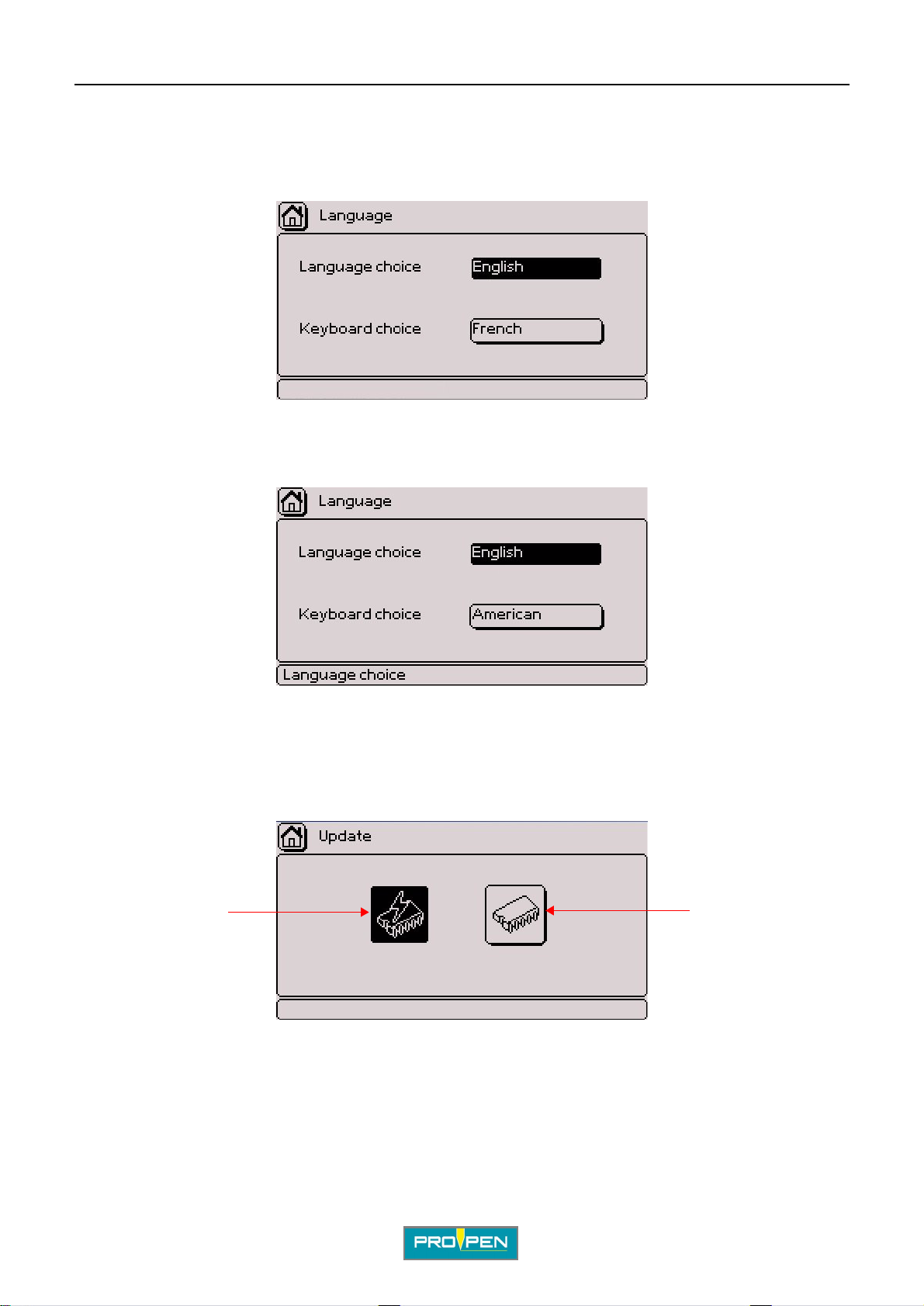
A"Machine configuration" menu
6. Languag e
Used to translate the program in different languages.
The language of the program and the language of the keyboard are chosen separately.
Press Enter to access the entry fiel d. Sel ect the desired language using the arro w keys. Validate by pressing
Enter.
Example of a screen in English
G
The program adapts the keys of the keyboard to the keyboard language selected.
7. Update
The screen below appears:
12
1 : Software update
2 : Power firmware update
Ref. 92091 - P05_en_F
87/121
Page 88
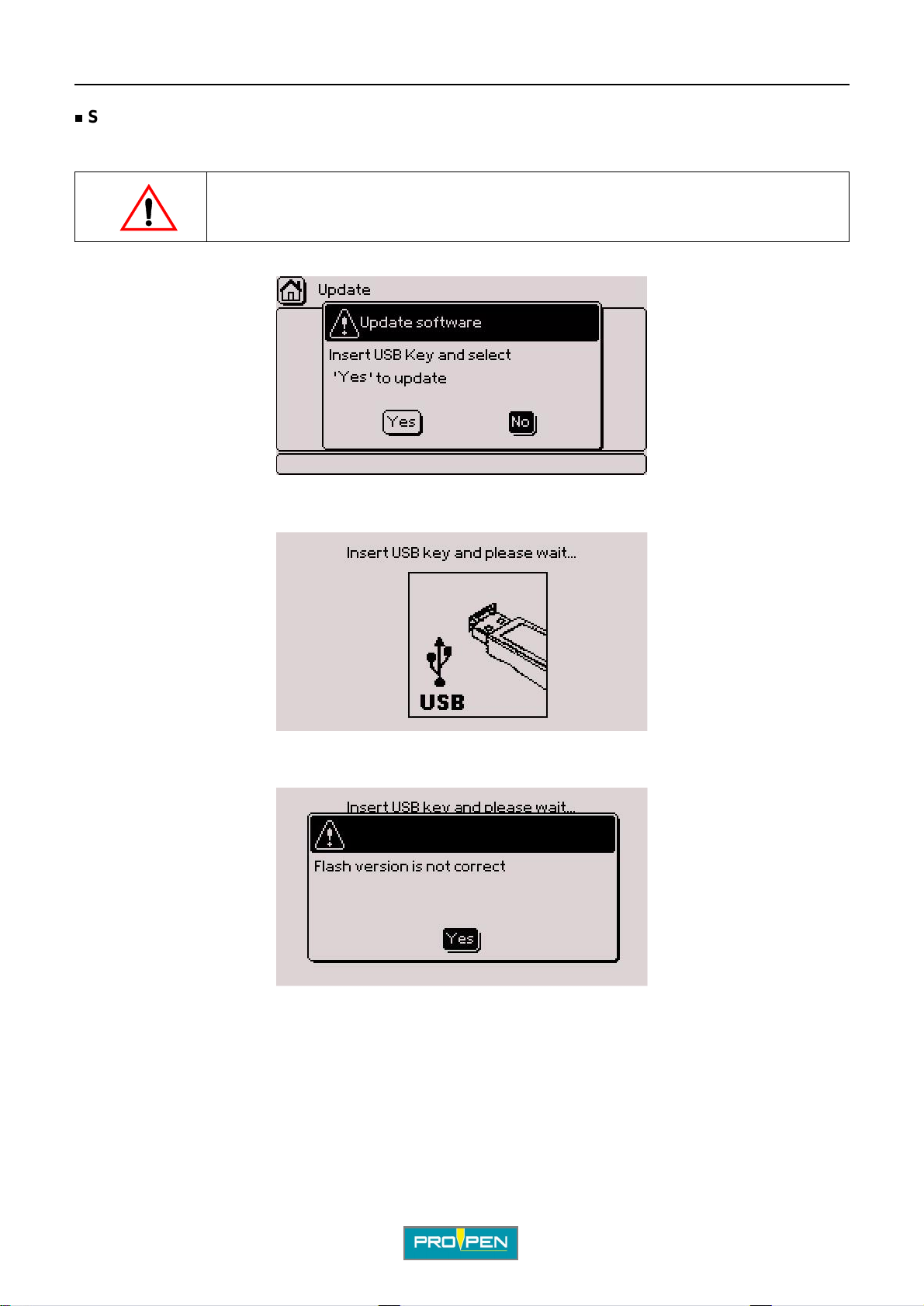
A"Machine configuration" menu
Software update
Used to update the program of the machine.
Before updating, make a backup copy of the files memori zed in t he machine (files, logos, fonts...).
Select the corresponding icon using the arrows. Validate by pressing Enter. The screen below appears:
No: Return to previous screen Yes: The screen below appears:
G
If several versions of the program are present on the key or if the serial number is incorre ct, the following
message is displayed:
V alidate by pres sing Enter . The pr ogram returns to the previous menu. Check the content of the key and try again.
The key must contain only one updated versio n of the pr ogram.
Ref. 92091 - P05_en_F
88/121
Page 89
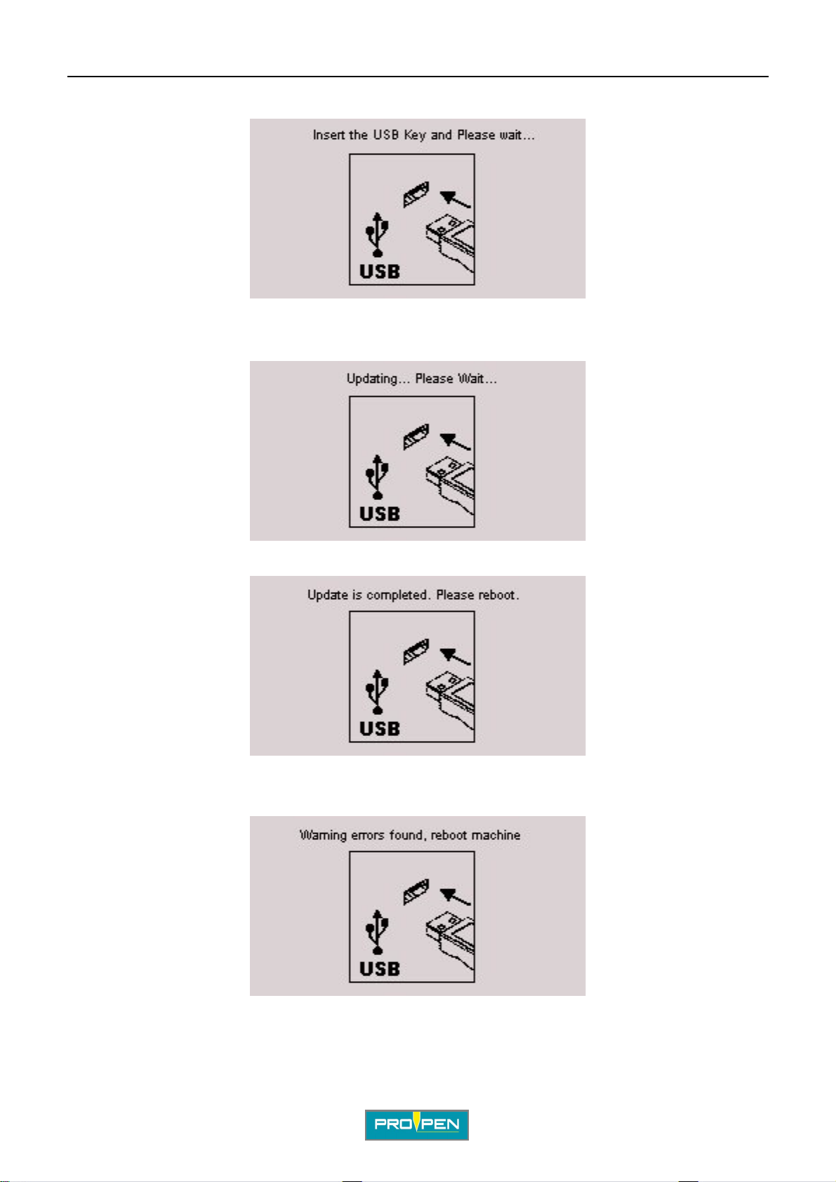
A"Machine configuration" menu
After insertin g the key, the screen switches off for a short period. The screen below appears:
Leave the key inserted during the update.
During the update, the screen below is displayed:
G
At the end of the update, the screen below appears:
Withdraw the key. Switch off and rest art the machine.
If an error is detected during the update, the following message is displayed:
Withdraw the key. Switch off and rest art the machine.
Check the content of the key and try again.
Ref. 92091 - P05_en_F
89/121
Page 90
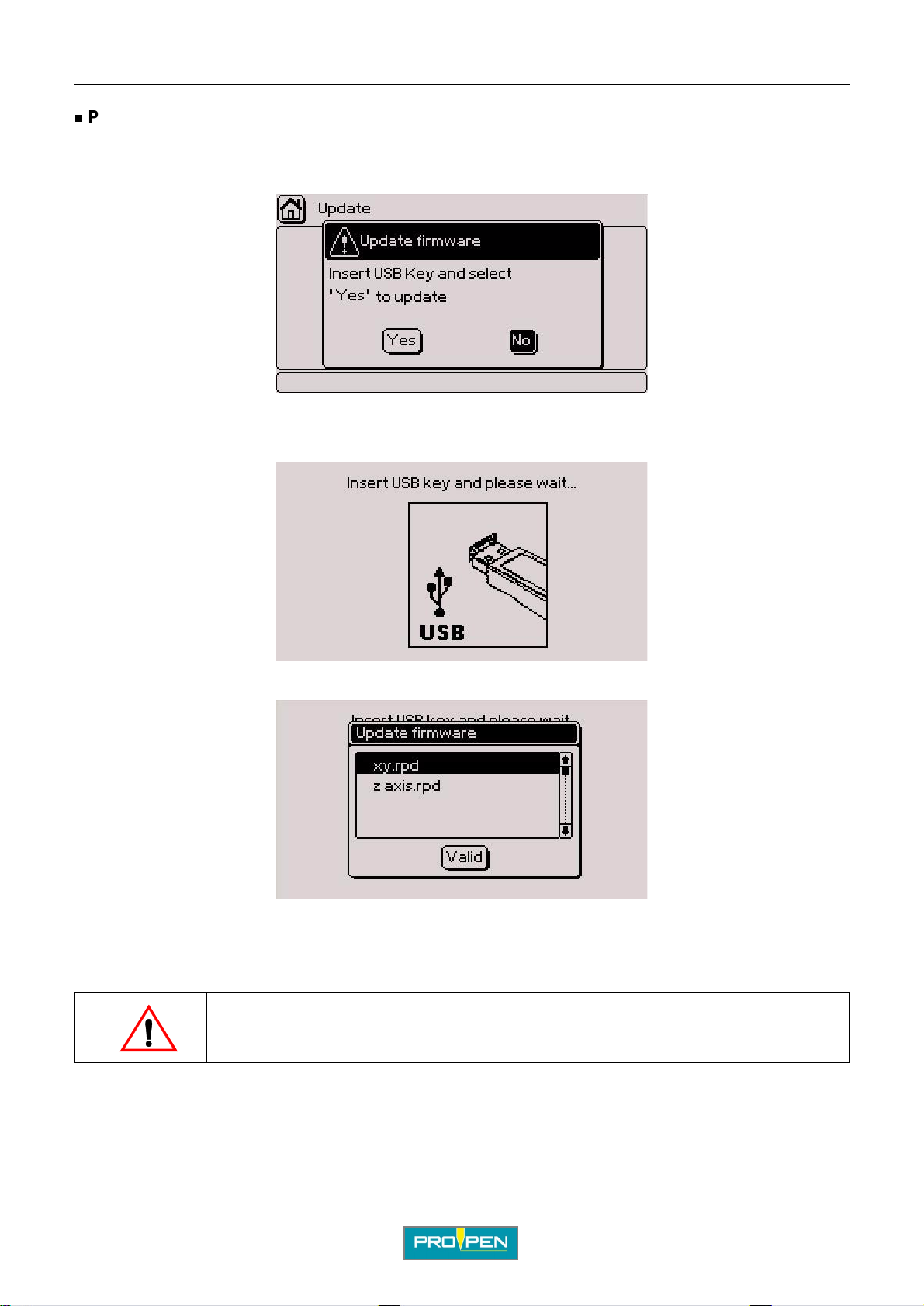
A"Machine configuration" menu
Power firmware update
Used to update the power card of the machine and its accessories.
Select the corresponding icon using the arrows. Validate by pressing Enter. The screen below appears:
No: Return to previous screen
Yes: The screen below appears:
G
Insert a USB key into the USB port for download. The screen below appears:
Select the file corresponding to what i s to updat e (head’s power card, rotary device, etc). To select several files,
position on each desired file and press the Space bar. Validate by pressing Enter.
Leave the key inserted during the update.
Do not cut the power or turn off the machine when updating.
In case of a power outage during updat ing, complete parameter ing is necessary in our
facilities.
Ref. 92091 - P05_en_F
90/121
Page 91
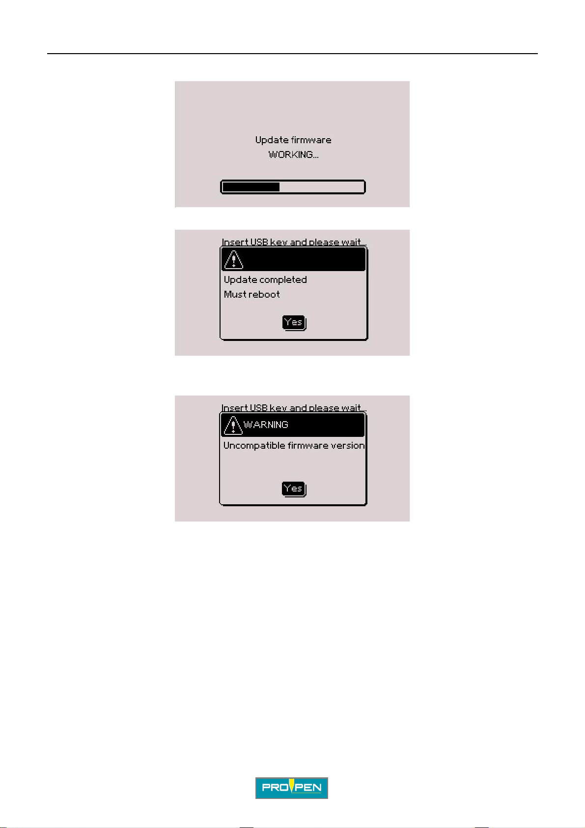
A"Machine configuration" menu
During the update, the screen below is displayed:
At the end of the update, the screen below appears:
G
Withdraw the key. Validate by pressing Enter. The machine is turned on and resetted.
If the power driver’s version is not compatib le, the following message appears:
Validate by pressing Enter. The program returns to the previo us men u. Contact us.
Ref. 92091 - P05_en_F
91/121
Page 92
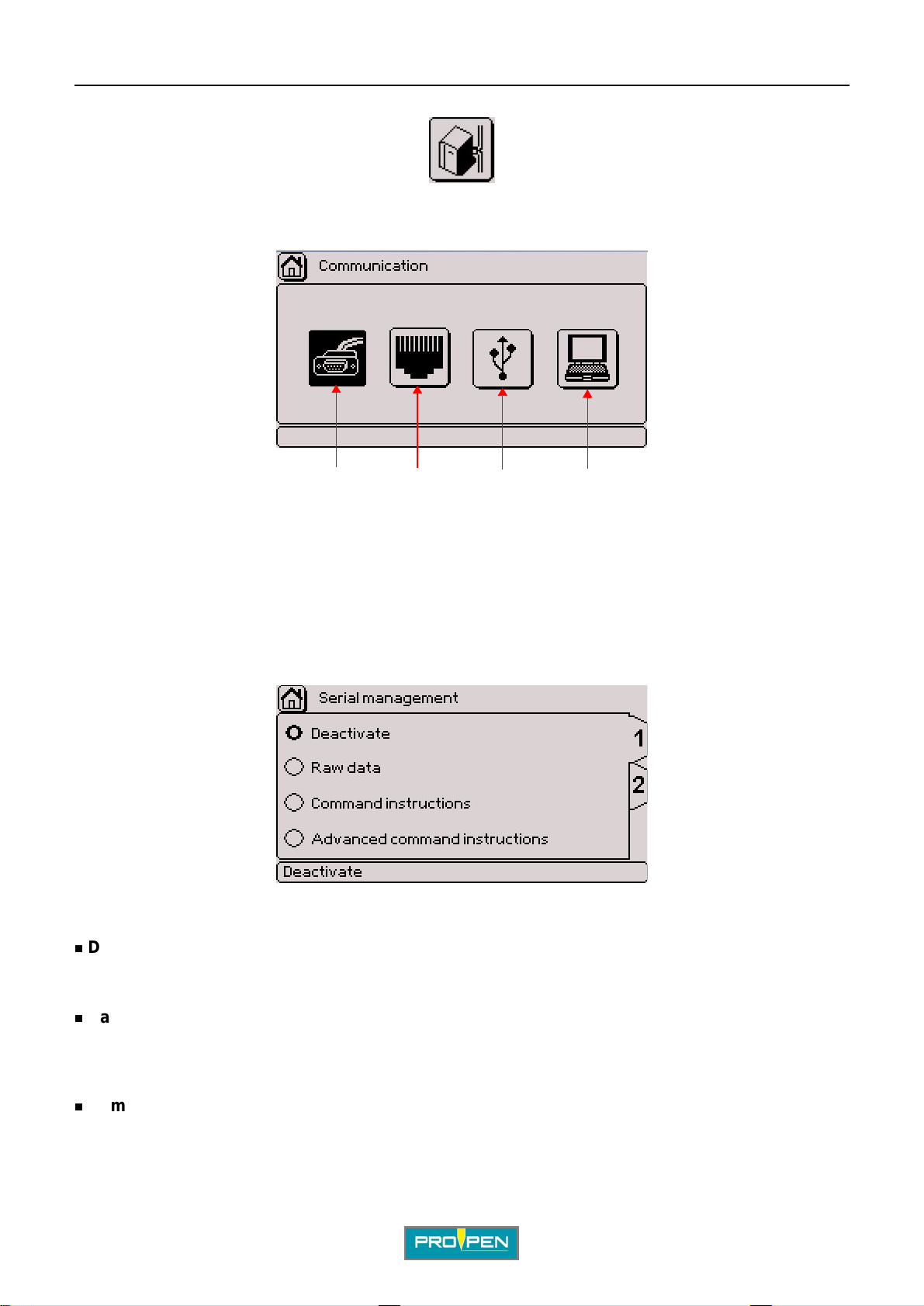
H"Communication" menu
Select this menu from the main menu, represented by the icon:
The screen below appears:
1432
H
1 : Serial management
2 : Ethernet port management
3 : USB port management
4 : Slave mode
1. Serial management
The screen below appears:
TAB 1:
Deactivate
Used for port deactivation.
Raw data
Used to send/receive unprocessed text without the protocol in order to communicate with basic equipment (i.e:
bar code reader).
Command instructions
MENU UNDER CONSTRUCTION
Ref. 9209 1 - P05_en_F
92/121
Page 93
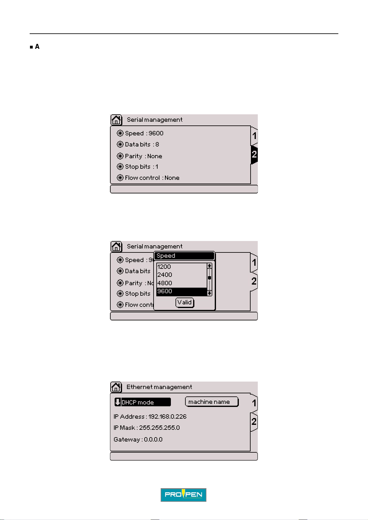
A"Communication" menu
Advanced command instructions
MENU UNDER CONSTRUCTION
Use the Tab key or the keyboard arrows to go to the 2 tab.
TAB 2:
The screen below appears:
This tab is used for po rt confi gura tion. Use the Up - Down - Lef t - Ri ght arr ows t o move to ot her fi elds. Pres s Enter
to access the entry field.
H
For each field, a window containing various possible options opens.
Example: speed - The screen below appears:
Select the desired configuratio n with the up-down arrows. Validate by pressi ng Enter.
Start over for each area if necessary.
2. Ethernet po rt m anagement
The screen below appears:
Ref. 92091 - P05_en_F
93/121
Page 94
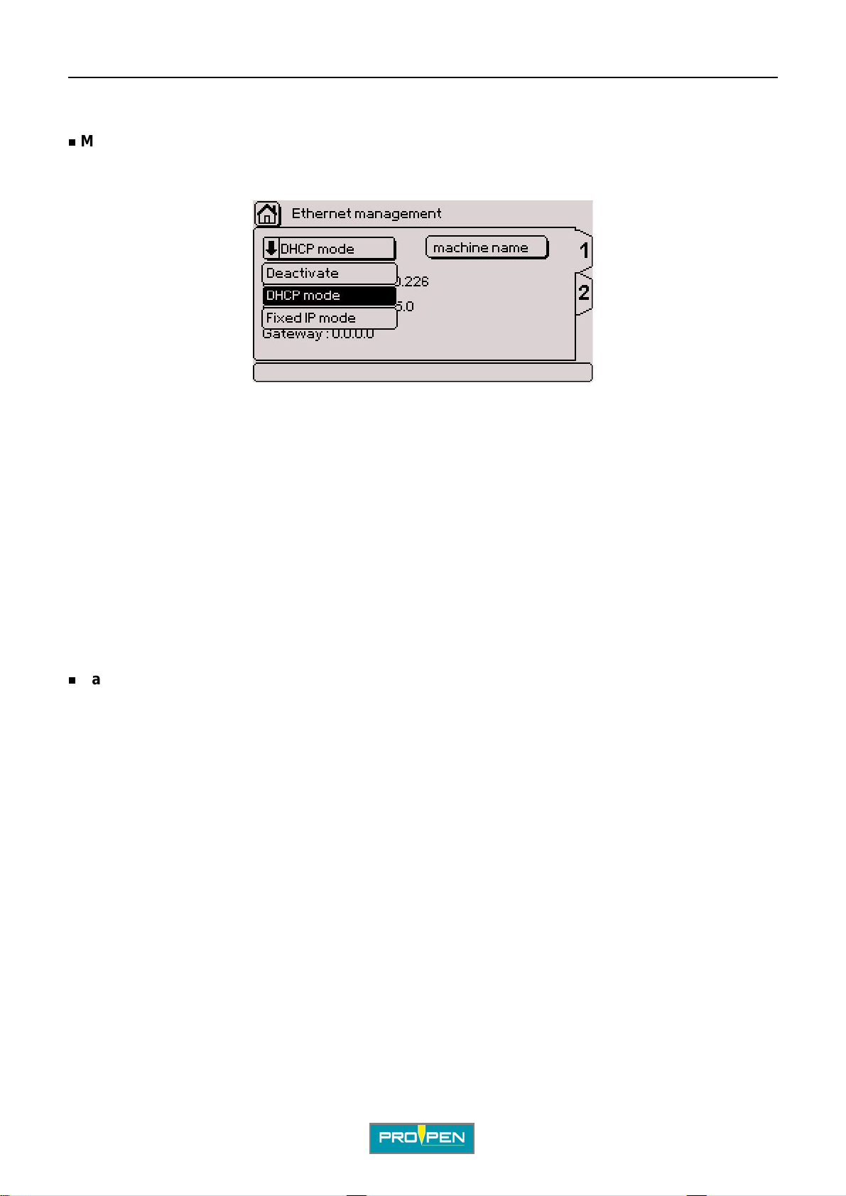
A"Communication" menu
TAB 1:
Mode
Used to choose the operating mode of the Ethernet port.
Press Enter to access the entry fiel d. The scr een below appears:
Deactivate
Used for port deactivation.
DHCP mode
H
When this mode is activated, the TCP/IP protocol is select ed and the machine’s IP address is automaticall y
searched when turned on. If a DHCP server exists on the same network as the machine, it can obtain an IP
address.
This mode is selected by default.
Fixed IP mode
When this mode is activated, the machine’s IP address is manually entered.
To enter data, move to the "IP Address", "IP Mask" or "Gat eway" fiel ds with the arrows . Press Enter to access the
entry field. Enter the data. Press Enter to validate the entry.
Name of the machine
Used to name the machine on the network.
Press Enter to access the entry fiel d. Enter the data. Press Enter to valida te the entry.
Use the Tab key or the keyboard arrows to go to the 2 tab.
TAB 2:
MENU UNDER CONSTRUCTION
3. USB port management
MENU UNDER CONSTRUCTION
4. Slave mode
MENU UNDER CONSTRUCTION
Ref. 92091 - P05_en_F
94/121
Page 95
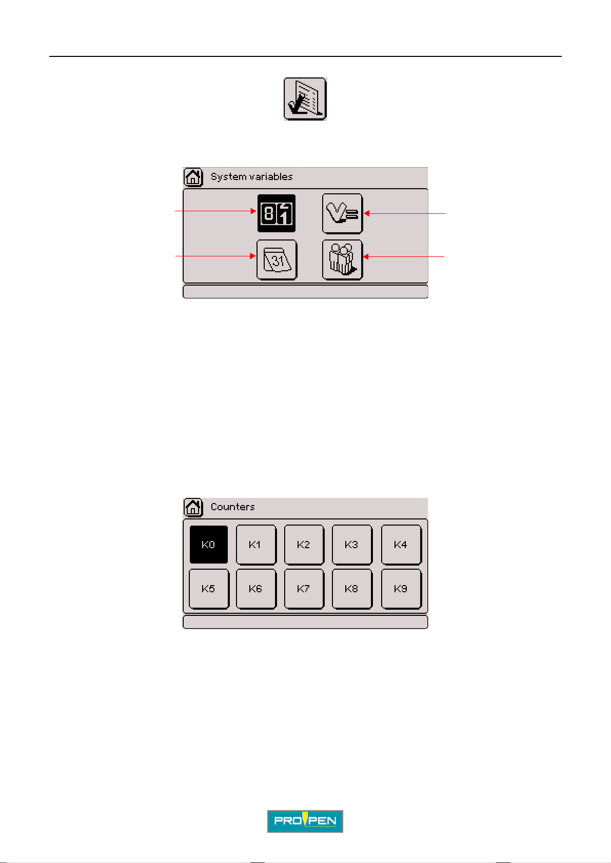
I"Variables" menu
Select this menu from the main menu, represented by the icon:
The screen below appears:
I
1
4
1 : Configuring counters
2 : Configuring variables
3 : Configuring shifts
4 : Configuring Day/Month/Year format
System variables are common to all marking files.
2
3
1. Configuring counters
Used to define increments/decrements for a serial number. The data is in numeri c mod e. 10 independent
counters are available. Each counter has an 8 digit code.
Identification key words go from K0 to K9.
The screen below appears:
Select the desired counter using the arrows. Validate by pressing En ter.
Ref. 9209 1 - P05_en_F
95/121
Page 96
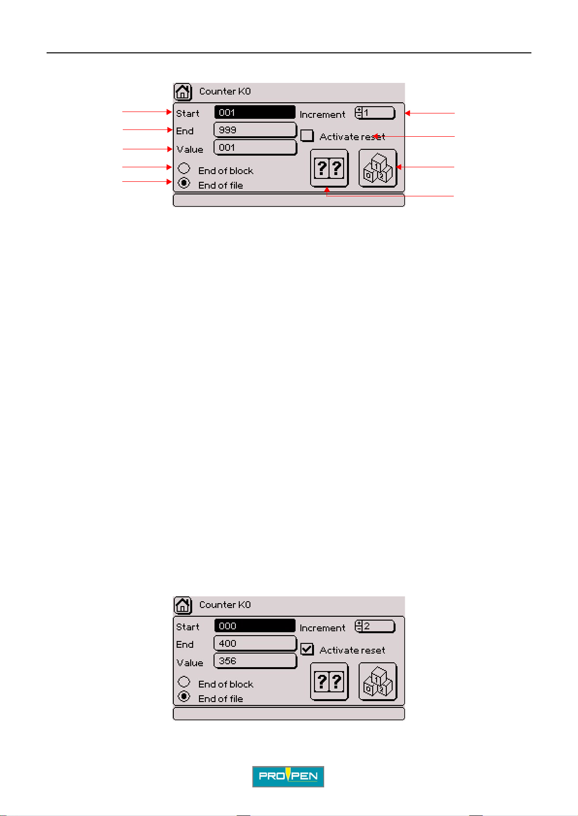
The screen below appears:
A"Variables" menu
I
1
2
6
7
3
4
8
5
9
1 : Indicates start value of counter.
2 : Indicates end value of counter.
3 : Indicates the counter value during marking.
4 : Incrementation of the counter’s value at the end of the block
5 : Incrementation of the counter’s value at the end of the file
6 : Indicates the incrementation value.
7 : Reset activation
8 : Setting the batch number
9 : Setting of the counter’s reset
To modify the "Start", "End" and "Value" fields, position the cursor on the desired field using t he arrows. Press
Enter to access the entry field. Enter the data. Press Enter to validate the entry.
The number of characters used for the start value also determi nes the minimum number of characters tha t will be
marked.
Example:
• start value: 1 => increment / decrement: 1, 2, 3, ...999
• start value: 001 => increment / decrement: 001, 002, 003, ...999
To modify the increment: Entry can be made either by:
• using the +/- keys on the numeric keypad
• pressing Enter then by typing the value directly on the keyboard
Incrementation of the counter’s value at the end of the bloc k / Inc rementation of the counter’s value at the end of
the file: Select one box or the other. Validate by pressing Enter.
Example:
Ref. 92091 - P05_en_F
96/121
Page 97
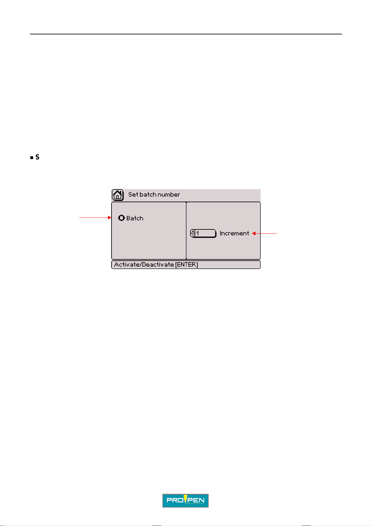
A"Variables" menu
In this situa tion:
• start value: 000
• end v alue: 400
• increment / decrement: 2
• next number to be marked: 356
• incrementation of the counter’s value at the end of the file
Note
Decrement function: The decrement func tion is activated when an end value inferior to the start value is
entered. In this case, the increment value is negative.
Setting the batch number
Used to determine the number of parts marked with the same number.
Select the corresponding icon using the arrows. Validate by pressing Enter. The screen below appears:
I
1
2
1 : Incrementation by batch
2 : Indicates the batch number.
Incrementation by batch
Go to the right part of the screen using the arrows. Select the number of parts to be marked with the same
number.
Ref. 92091 - P05_en_F
97/121
Page 98
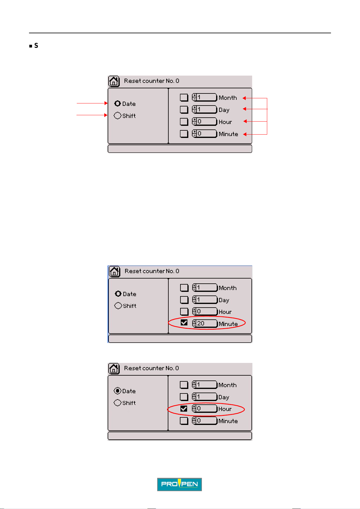
A"Variables" menu
Setting of the counter’s reset
To activate the counter’s reset, position the cursor on the corresponding box. Validate by pressing Enter.
Go to the icon of reset setting using the arrows. Validate by pressing Enter . The scr een below appears:
1
I
2
1 : Reset on a certain date
2 : Reset with each change of shift
3 : Choice of reset date
Select the reset type using the arrows. Validate by pressing Enter.
Reset on a certain date
Used to define a time or a dat e at which the counters must return to their initial value. Resetting a counter to zero
will impact all marking files.
Go to the right p art of the scr een us ing the arrows. Select the desi red boxes. Validate by pressing Enter. Go to the
corresponding areas to choose the reset date. Only the ticked boxes are taken into account.
Example 1: Reset every hour at 20 (00h20, 01h20, 2h20, etc...)
3
Example 2: Reset all days to 00:00
Ref. 92091 - P05_en_F
98/121
Page 99
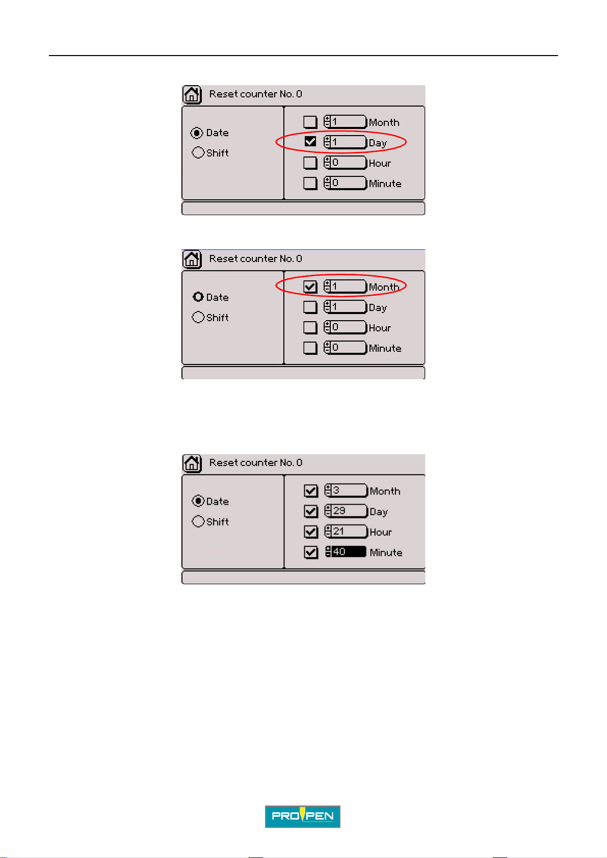
A"Variables" menu
Example 3: Reset to the 1st of each month
Example 4: Reset at 00:00 on January 1st (once a year)
I
Note
If the hours and minutes fields are not fille d in, the default val ue is 0. The value of the seconds i s always 0.
To obtain a reset once a year at a predefined date and time, fill in all the fields.
Example: Reset every year on March 29th at 21h40:
Reset with each change of shift
If this type of reset is selected, the counter returns to its init ial value with each change of shift.
See: "Configuring shifts "
Ref. 92091 - P05_en_F
99/121
Page 100
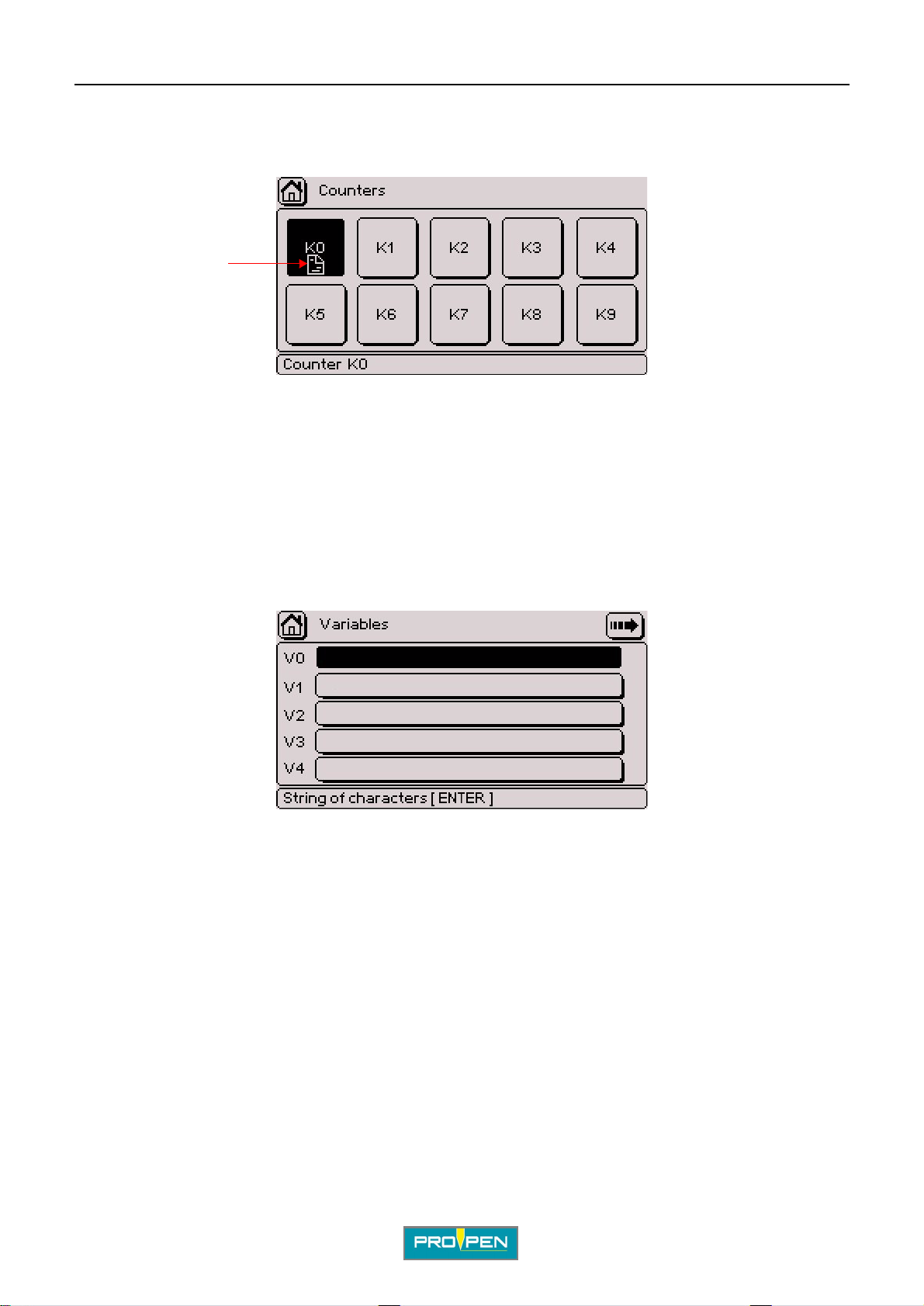
A"Variables" menu
Copying the contents of a counter
It is possible to copy all the characteristics from one counter to another. To do this, position the cursor on the
counter to be copied and simultaneous ly pr ess Ctrl + C on the keyboard. A symbol is shown:
"Copy" symbol
Using the arrows, position the cursor on the counter to which the characterist ics must be pasted and
simultaneously press Ctrl + V on the keyboard.
2. Configuring variabl es
Used to mark repetitive texts common to several marking files by indic ating the variable number in which the text
is contained.
Variables are memory blocks (10 in all) of text containing up to 255 characters. They are common to all marking
files and are saved in the CCU memory. They are identified by the key words V0 and V9.
I
The screen below appears:
The first 4 fields are displayed. Select the desired variable using the arrow keys. To access the following or
previous page, select the arrows in the upper right corner of the screen or press the Page Up - Page Down keys
on the keyboard.
Press Enter to access the entry fiel d. Enter the data. Press Enter to valida te the entry.
Ref. 92091 - P05_en_F
100/121
 Loading...