

Page 1

VessRAID
1000f, 1000i, 1000s Series
FC, iSCSI, SAS
Quick Start Guide
Kurzanleitung
Guide de démarrage rapide
Guida Introduttiva
Guía de inicio rápido
Руководство по быстрому
началу работы
クイックスタートガイド
快速安裝手冊
快速安装手册
빠른 시작 안내서
Version 3.0
© 2011 Promise Technology, Inc. All Rights Reserved.
Page 2

VessRAID 1000f, 1000i, 1000s Series Quick Start Guide
Contents
English. . . . . . . . . . . . . . . . . . . . . . . . . . . . . . . . . . . . . . . . . . . . . . . .3
Deutsch . . . . . . . . . . . . . . . . . . . . . . . . . . . . . . . . . . . . . . . . . . . . .48
Français . . . . . . . . . . . . . . . . . . . . . . . . . . . . . . . . . . . . . . . . . . . . .98
Italiano . . . . . . . . . . . . . . . . . . . . . . . . . . . . . . . . . . . . . . . . . . . . . 146
Español . . . . . . . . . . . . . . . . . . . . . . . . . . . . . . . . . . . . . . . . . . . . . 192
Pусский язык . . . . . . . . . . . . . . . . . . . . . . . . . . . . . . . . . . . . . . . . 241
日本語 . . . . . . . . . . . . . . . . . . . . . . . . . . . . . . . . . . . . . . . . . . . . . .290
繁體中文 . . . . . . . . . . . . . . . . . . . . . . . . . . . . . . . . . . . . . . . . . . . . 336
简体中文 . . . . . . . . . . . . . . . . . . . . . . . . . . . . . . . . . . . . . . . . . . . . 381
한국어 . . . . . . . . . . . . . . . . . . . . . . . . . . . . . . . . . . . . . . . . . . . . . .425
2
Page 3
Task 1: Unpacking the VessRAID
VessRAID Task List
• Task 1: Unpacking the VessRAID (page 3)
• Task 2: Installing the LCD Panel (Optional) (page 7)
• Task 3: Mounting VessRAID in a Rack (page 9)
• Task 4: Installing Disk Drives (page 12)
• Task 5: Making Data and Management Connections (page 15)
• Task 6: Setting Up Serial Cable Connections (page 29)
• Task 7: Connecting the Power (page 30)
• Task 8: Setting the IP Address (page 34)
• Task 9: Creating Logical Drives with WebPAM PROe (page 40)
• Contacting Technical Support (page 47)
Task 1: Unpacking the VessRAID
The VessRAID box contains the following items:
• VessRAID Unit
•
Quick Start Guide
• RJ11-to-DB9 serial data cable
• Screws for disk drives
(70 pieces for 16-bay, 50 pieces
for 12- and 8-bay)
printed
• 1.5m (4.9 ft) Power cords
(1700 models, 1; 1800 models, 2)
• CD with SNMP files,
and
Manual
PDF format
Quick Start Guide
Product
in
A Battery Backup Unit (BBU) is optional on the VessRAID subsystem. In the
event of a power failure, the BBU powers the controller cache to preserve any
data it contains.
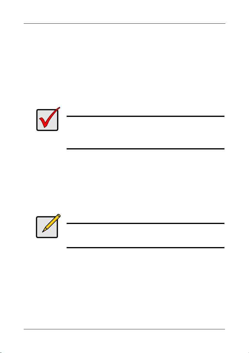
Warning
This is a Class A product. In a domestic environment this product
may cause radio interference in which case the user may be
required to take adequate measures.
Warning
The electronic components within the VessRAID enclosure are
sensitive to damage from Electro-Static Discharge (ESD).
Observe appropriate precautions at all times when handling the
VessRAID or its subassemblies.
3
Page 4

VessRAID 1000f, 1000i, 1000s Series Quick Start Guide
Caution
• There is a risk of explosion if the battery is replaced by the
incorrect type.
• Dispose of used batteries according to the instructions that
accompany the battery.
VessRAID Model Line-up
Model Interface
Number
of Drives
Drive
Carriers
Power
Supplies
Controller
Fans
1840f+ Fibre Channel 16 plus 2 external
1840f Fibre Channel 16 original 2 internal
1840i+ iSCSI 16 plus 2 external
1840i iSCSI 16 original 2 internal
1840s+ SAS 16 plus 2 external
1840s SAS 16 original 2 internal
1830i+ iSCSI 12 plus 2 external
1830i iSCSI 12 original 2 internal
1830s+ SAS 12 plus 2 external
1830s SAS 12 original 2 internal
1820i iSCSI 8 original 2 internal
1740i iSCSI 16 original 1 internal
1740s SAS 16 original 1 internal
1730i iSCSI 12 original 1 internal
1730s SAS 12 original 1 internal
1720i+ iSCSI 8 plus 1 external
1720i iSCSI 8 original 1 internal
4
Page 5

Task 1: Unpacking the VessRAID
Drive Carrier LEDs
Drive Carriers
Power and Status LEDs
Drive Carrier LEDs
Drive Carriers Power and Status LEDs
External Fans
SAS RAID ControllerDual Power Supplies
Figure 1. 12-bay VessRAID with the “original” drive carrier design
Figure 2. 12-bay VessRAID with the “plus” drive carrier design
A defective drive may be replaced without interruption of data availability to the
host computer. If so configured, a hot spare drive will automatically replace a
failed drive, securing the fault-tolerant integrity of the logical drive. The selfcontained hardware-based RAID logical drive provides maximum performance in
a compact external enclosure.
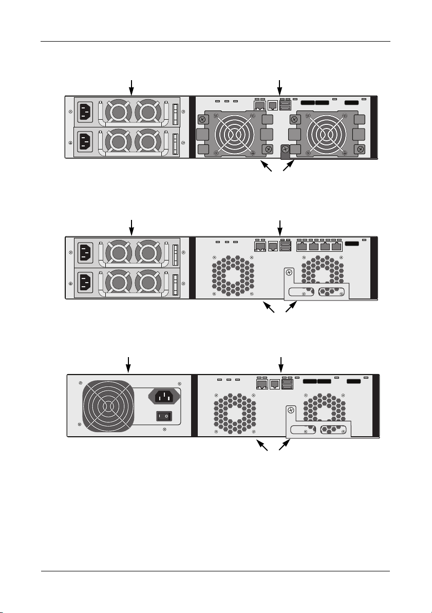
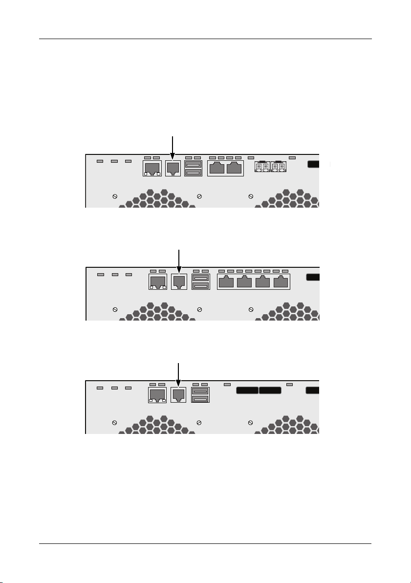
Figure 3. VessRAID 1840f+ rear view
5
Page 6
VessRAID 1000f, 1000i, 1000s Series Quick Start Guide
SAS RAID ControllerDual Power Supplies
External Fans
iSCSI RAID Controller
Internal Fans
Dual Power Supplies
Internal Fans
SAS RAID ControllerSingle Power Supply
Figure 4. VessRAID 1830s+ rear view
Figure 5. VessRAID 1830i rear view
Figure 6. VessRAID 1730s rear view
For a description of the LEDs, see pages 30 and 31.
6
Page 7
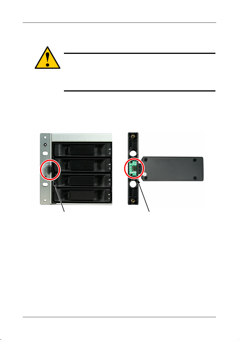
Task 2: Installing the LCD Panel (Optional)
Connector on
the LCD panel
Connector on
the enclosure
Task 2: Installing the LCD Panel (Optional)
Cautions
• The LCD panel is NOT a hot-swap device. Be sure the
VessRAID is powered down before you connect or disconnect
the LCD panel.
• You must install the LCD panel before you mount the
VessRAID subsystem in a rack.
The LCD panel mounts to the left ear of the VessRAID enclosure.
1. Align the connector on the left bracket of the VessRAID enclosure to the
connector on the back of the LCD panel, as shown in
Figure 7. Align the connectors on the enclosure and the LCD panel
Figure 7.
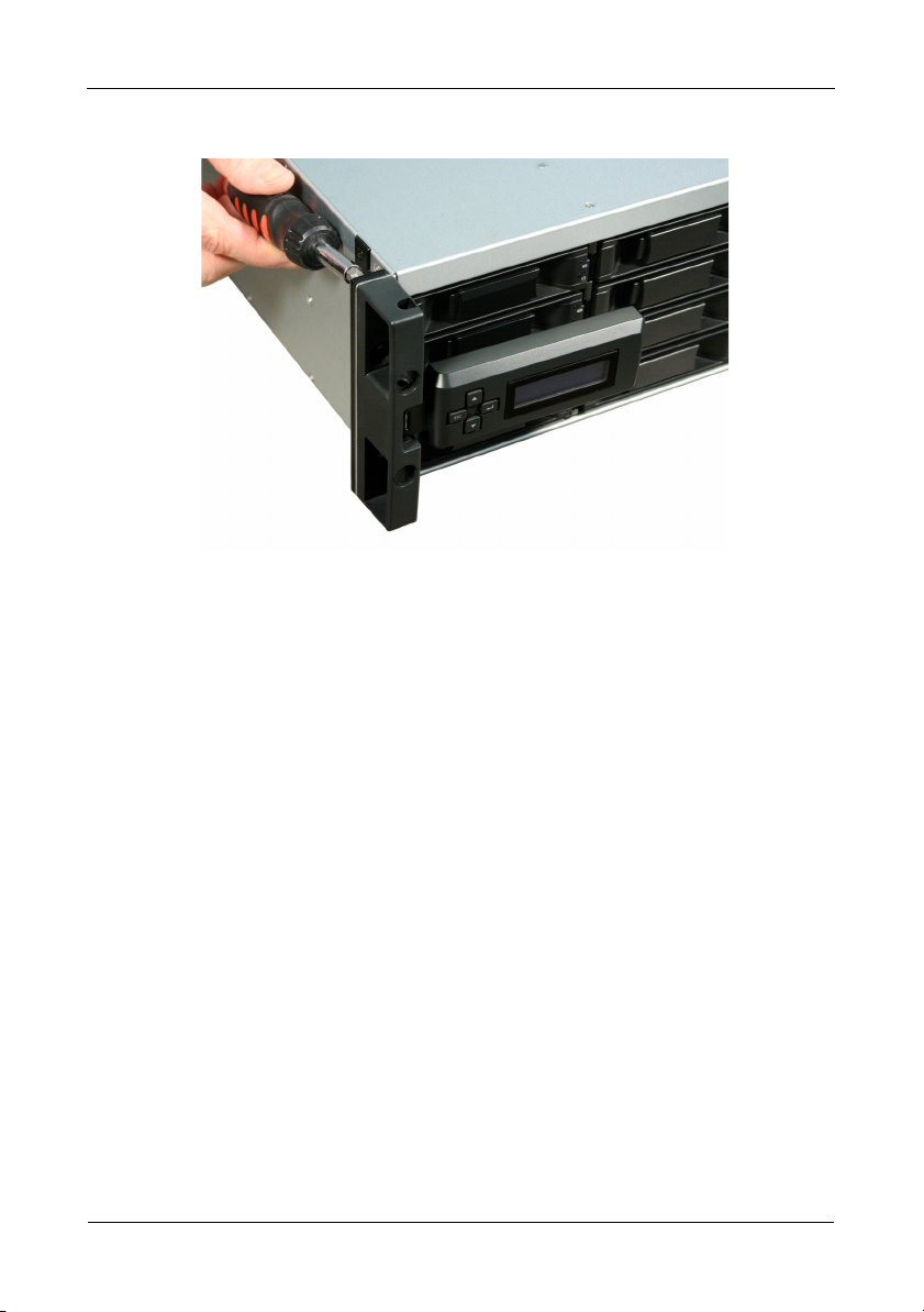
2. Insert the two attaching screws through the holes in the left bracket and into
the threaded holes in the LCD panel, as shown in
Tighten the screws to secure the LCD panel to the bracket.
7
Figure 8.
Page 8
VessRAID 1000f, 1000i, 1000s Series Quick Start Guide
Figure 8. Attaching the LCD panel to the VessRAID enclosure
The LCD screen activates when the VessRAID boots. See “Task 7: Connecting
the Power” on page 30.
Go to “Task 3: Mounting VessRAID in a Rack” on page 9.
8
Page 9
Task 3: Mounting VessRAID in a Rack
Task 3: Mounting VessRAID in a Rack
Cautions
• At least two persons are required to safely lift, place, and
attach the VessRAID unit into a rack system.
• Do not lift or move the VessRAID unit by the handles, power
supplies or the controller units. Hold the subsystem itself.
• Do not install the VessRAID unit into a rack without rails to
support the subsystem.
• Only a qualified technician who is familiar with the installation
procedure should mount and install the VessRAID unit.
• Be sure all switches are OFF before installing the VessRAID
unit or exchanging components.
• Mount the rails to the rack using the appropriate screws and
flange nuts, fully tightened, at each end of the rail.
• Do not load the rails unless they are installed with screws as
instructed.
• The rails available for the PROMISE VessRAID unit are
designed to safely support that PROMISE VessRAID unit
when properly installed. Additional loading on the rails is at
the customer’s risk.
• PROMISE Technology, Inc. cannot guarantee that the
mounting rails will support your PROMISE VessRAID unit
unless you install them as instructed.
Note
To lighten the VessRAID enclosure, remove the power supplies.
Replace the power supplies after the VessRAID unit is mounted in
your rack.
The VessRAID subsystem installs to the rack using the available mounting rails.
You can also use your existing rails.
9
Page 10
VessRAID 1000f, 1000i, 1000s Series Quick Start Guide
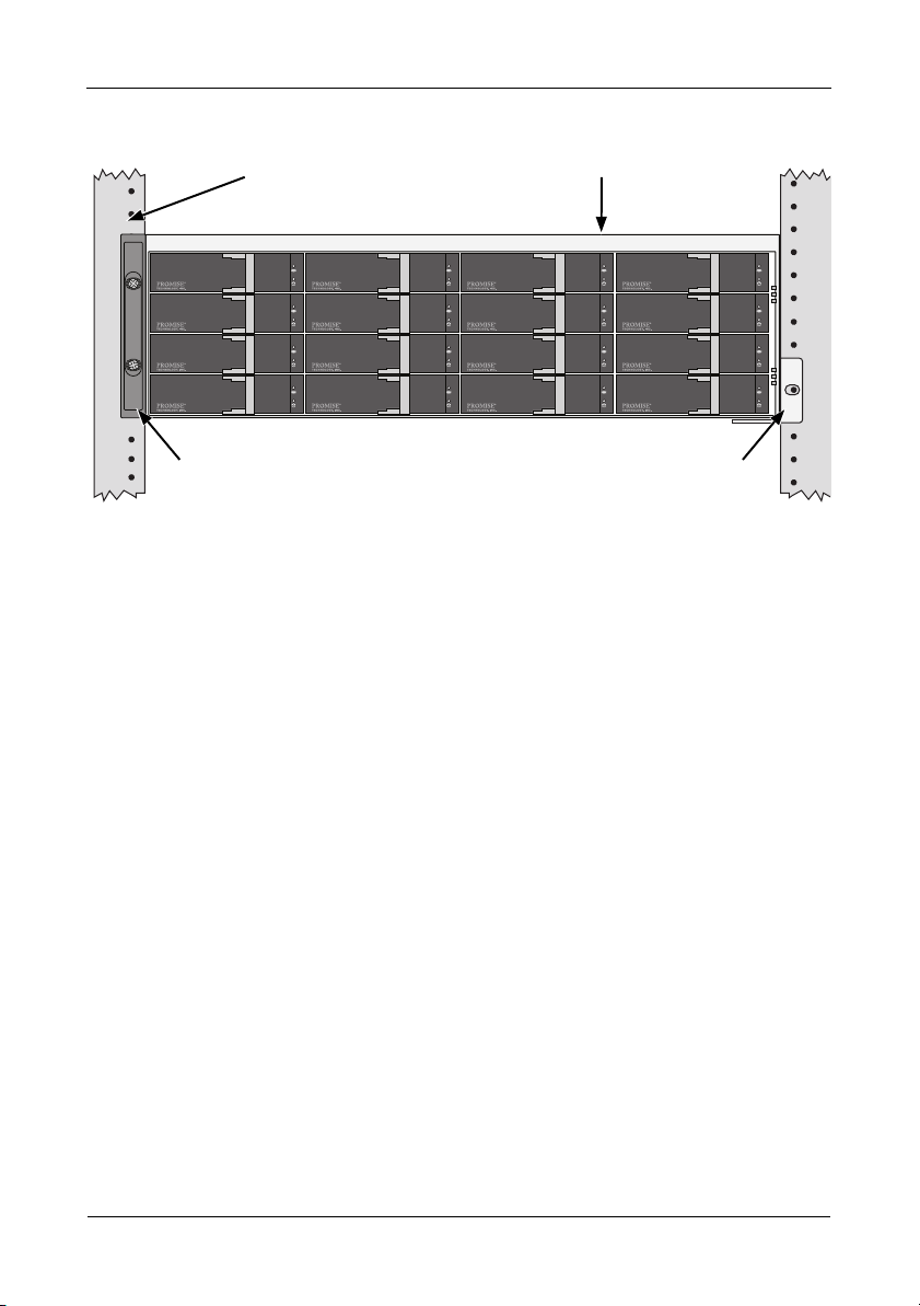
Vertical Rack Post VessRAID subsystem
Mounting rails mount
outside the rack post
Handles mount
outside the rack post
Figure 9.
A 16-bay VessRAID mounted in a rack with the available rails
To install the VessRAID subsystem into a rack with the available mounting rails:
1. Check the fit of the mounting rails in your rack system.
See page 11, Figure 10.
2. Adjust the length of the mounting rails as needed.
The rear rail slides inside the front rail. The rail halves are riveted together
and use no adjustment screws.
3. Attach the mounting rail assemblies to the outside of the rack posts, using
the attaching screws and flange nuts from your rack system.
Be sure the front rail support is on the bottom facing inward.
The alignment pins fit into the rack holes above and below the attaching
screws.
Use the attaching screws and flange nuts from your rack system. Tighten the
screws and flange nuts according to your rack system instructions.
4. Place the VessRAID subsystem onto the rails.
5. Secure the VessRAID subsystem to the rack.
One screw each side, in the upper hole only. Use the attaching screws and
flange nuts from your rack system. Tighten the screws and flange nuts
according to your rack system instructions.
10
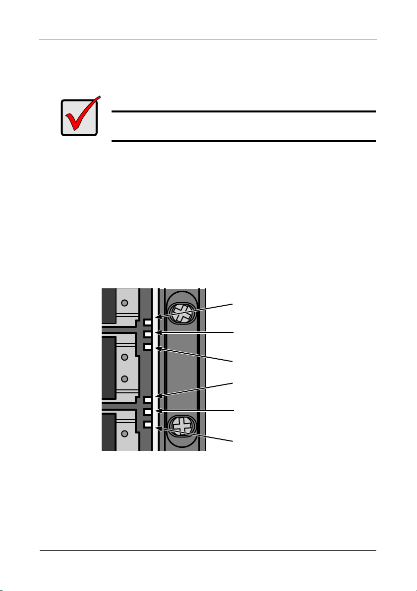
Page 11
Task 3: Mounting VessRAID in a Rack
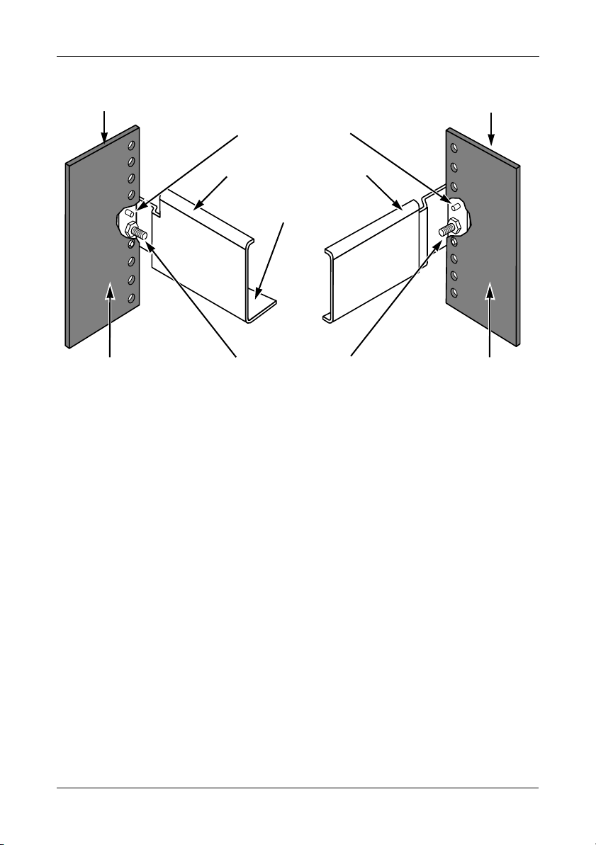
Inside of post
Rack front post
Rail attaching screws
(not included)
Alignment pins
two on each flange
Inside of post
Rack rear post
Front rail
Rear rail
Support for
subsystem
Note that only the front rail has a support for the subsystem.
Figure 10.Rack mount assembly diagram
This completes rack mounting. Go to “Task 4: Installing Disk Drives” on page 12.
11
Page 12
VessRAID 1000f, 1000i, 1000s Series Quick Start Guide
1
5
9
13
2
6
10
14
3
7
11
15
4
8
12
16
Task 4: Installing Disk Drives
The VessRAID subsystems and VessJBOD expansion units support:
• SAS and SATA hard disk drives
• 3.5-inch hard disk drives
For a list of supported physical drives, download the latest compatibility list from
the PROMISE
Number of Drives Required
The table below shows the number of drives required for each RAID level
Level Number of Drives Level Number of Drives
RAID 0 1 or more RAID 6 4 to 32*
RAID 1 2 only RAID 10 4 or more**
RAID 1E 2 or more RAID 30 6 or more
RAID 3 3 to 32* RAID 50 6 or more
RAID 5 3 to 32* RAID 60 8 or more
* A JBOD expansion unit may be required.
** Must be an even number of drives.
support website.
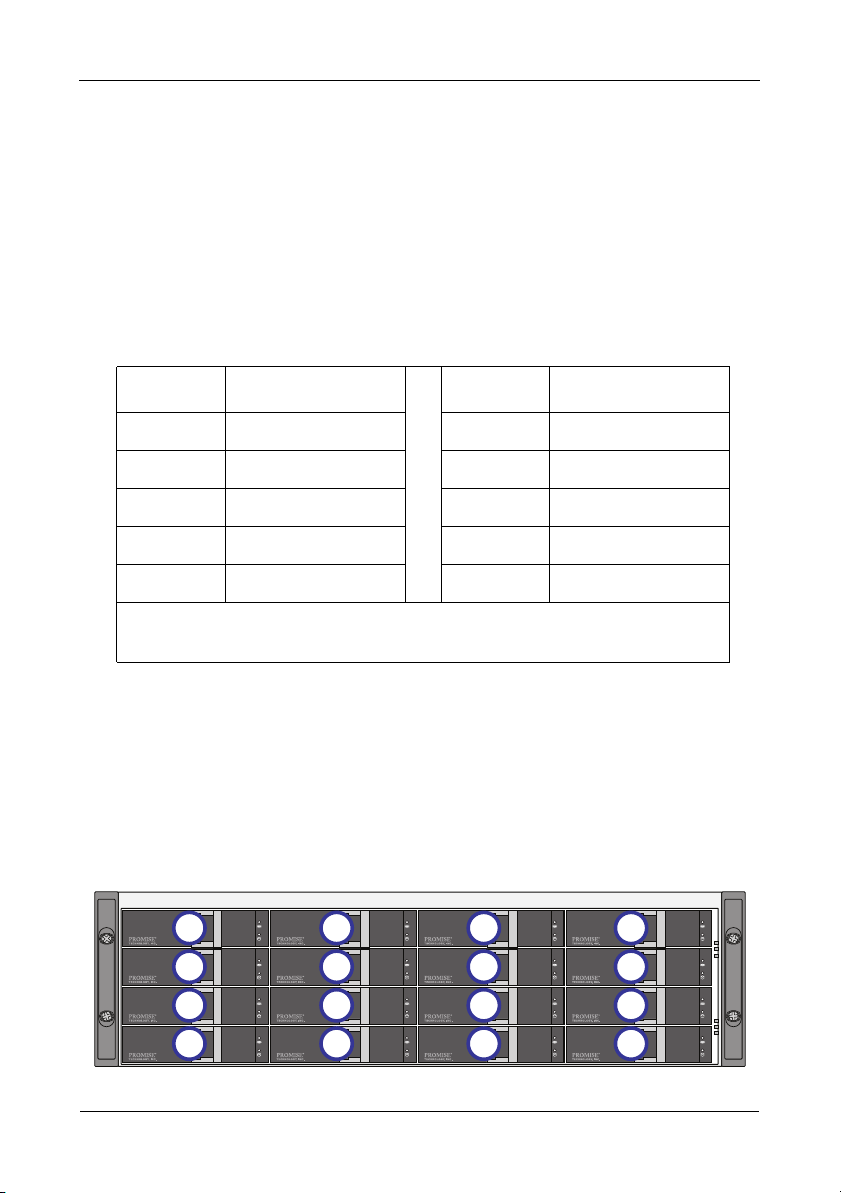
Drive Slot Numbering
You can install any suitable disk drive into any slot in the enclosure. The diagram
below shows how VessRAID’s drive slots are numbered. Whether you have the
original or plus carriers, the slots are numbered the same.
Slot numbering is reflected in the WebPAM PROe and CLU user interfaces. See
Figures 11, 12, and 13.
Figure 11. 16-bay VessRAID drive slot numbering
12
Page 13
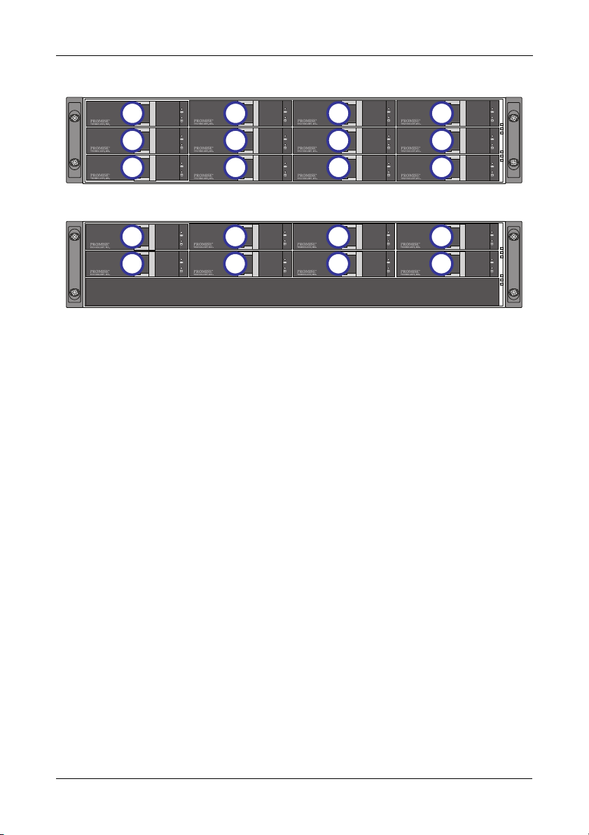
Figure 12.12-bay VessRAID drive slot numbering
Task 4: Installing Disk Drives
1
5
9
Figure 13.8-bay VessRAID drive slot numbering
1
5
Install all of the drive carriers into the VessRAID enclosure to ensure proper
airflow, even if you do not populate all the carriers with disk drives.
2
6
10
2
6
11
3
7
4
8
12
3
7
4
8
Installing Your Disk Drives
To install your disk drives:
1. Remove a disk drive carrier.
2. Carefully lay the disk drive into the drive carrier at the front, so that the screw
holes on the sides line up.
See page 14, Figure 14.
3. Insert the screws through the holes in the drive carrier and into the sides of
the disk drive.
• Install only the counter-sink screws supplied with the VessRAID.
• Install four screws per drive.
• Snug each screw. Be careful not to over-tighten.
4. Reinstall the drive carrier into the VessRAID enclosure.
Repeat steps 1 through 3 until all of your disk drives are installed.
13
Page 14

VessRAID 1000f, 1000i, 1000s Series Quick Start Guide
Disk drive
mounting screw
mounting screw
Figure 14.Disk drive mounted in a drive carrier
This completes disk drive installation. Go to “Task 5: Making Data and
Management Connections” on page 15.
Caution
VessRAID supports disk drive hot-swapping. To avoid hand
contact with an electrical hazard, do not remove more than one
drive carrier a time.
14
Page 15
Task 5: Making Data and Management Connections
Task 5: Making Data and Management Connections
You can configure your VessRAID for:
• Fibre Channel Direct Attached Storage (DAS), see below
• Fibre Channel Storage Area Network (SAN) (page 18)
• iSCSI Direct Attached Storage (DAS) (page 20)
• iSCSI Storage Area Network (SAN) (page 22)
• SAS Direct Attached Storage (DAS) (page 25)
• SAS JBOD Expansion (page 27)
Important
For a list of supported FC HBAs, Switches and SFPs, download
the latest compatibility list from the PROMISE
VessRAID does not support cascading of multiple RAID
subsystems. Cascading is planned for a future release.
Fibre Channel Direct Attached Storage (DAS)
This arrangement requires:
• A Fibre Channel (FC) interface card in the Host PC
• At least one FC transceiver for each VessRAID subsystem
• A network interface card (NIC) in the Host PC
• A standard network switch
support website.
Note
VessRAID Fibre Channel subsystems also have two (2) Ethernet
RJ45 iSCSI Port connectors. See
(DAS)” on page 20 for connection instructions.
“iSCSI Direct Attached Storage
Data Path
The VessRAID controller has two (2) FC Port connectors and one (1) SFF-8088
SAS Expansion Port connector. See
To establish the data path:
1. Install an FC transceiver into the FC data port on the VessRAID controller.
See page 17, Figure 16.
2. Connect the FC transceiver on the VessRAID controller to the Host PC or
Server.
See also “SAS JBOD Expansion” on page 27.
page 16, Figure 15.
15
Page 16
VessRAID 1000f, 1000i, 1000s Series Quick Start Guide
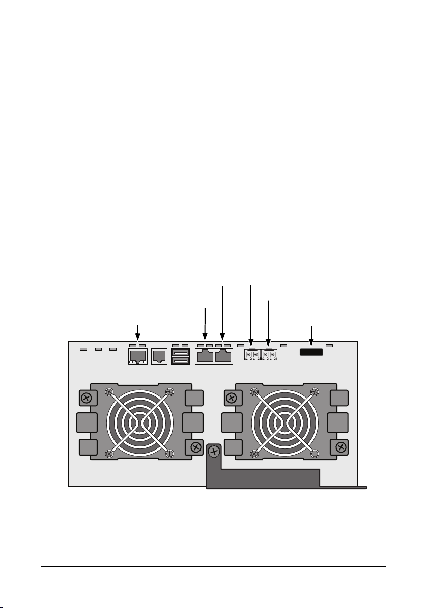
iSCSI data port 1
Management port
iSCSI data port 2
FC data port 2
FC data port 1
SAS expansion
port (to JBOD)
Management Path
The VessRAID controller has one (1) Ethernet RJ-45 Management Port
connector. See
To establish the management path:
1. Attach one end of an Ethernet cable to the network connector or standard
NIC in the Host PC.
Attach the other end of the Ethernet cable to one of the ports on the standard
network switch.
See page 17, Figure 16.
2. Attach one end of an Ethernet cable to one of the ports on the standard
network switch.
Attach the other end of the Ethernet cable to the Management Port on the
VessRAID subsystem.
If you have multiple VessRAID subsystems, Host PCs or Servers, repeat
steps 1 and 2 as required.
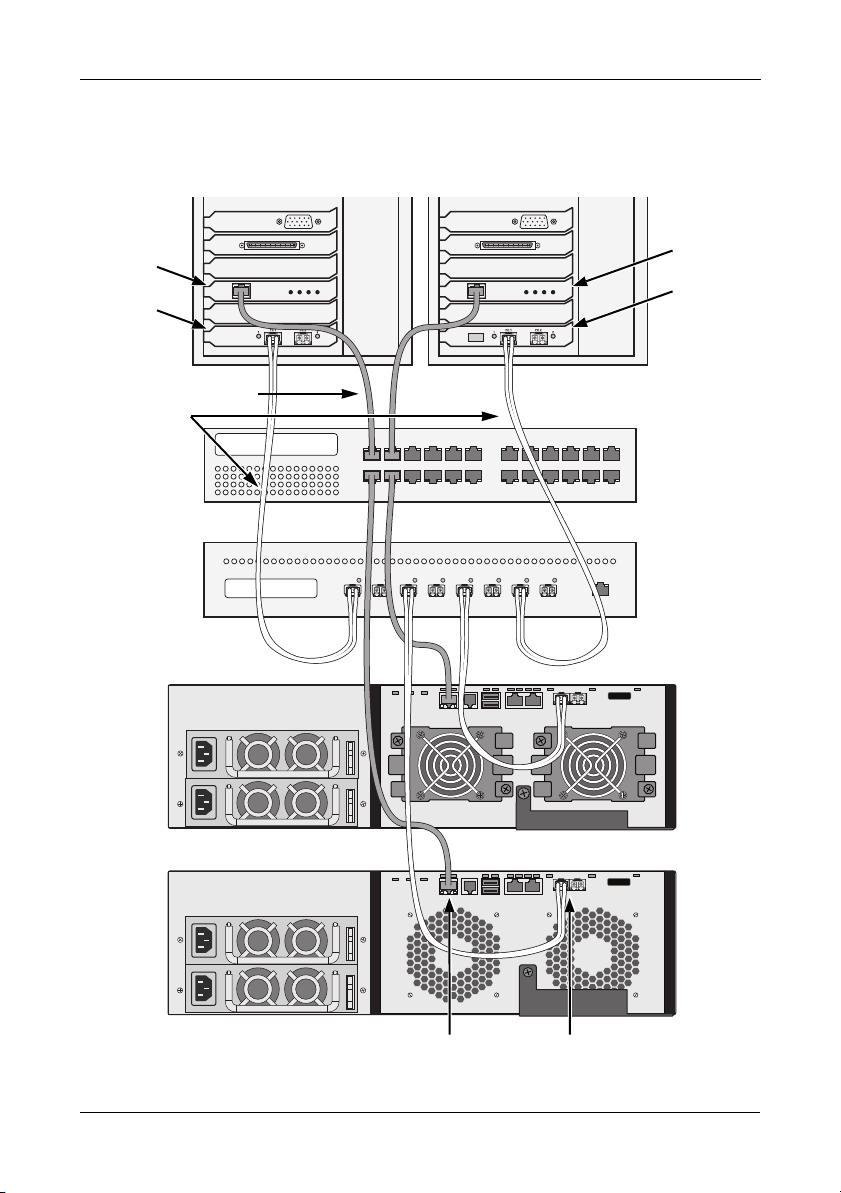
Figure 15.VessRAID 1840f+ data and management ports. 1840f is similar
Figure 15.
16
Page 17
Task 5: Making Data and Management Connections
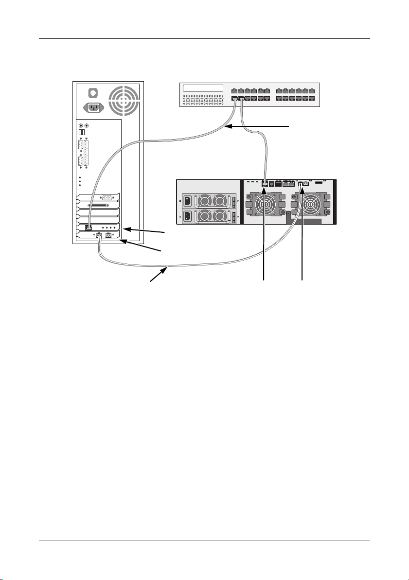
NIC
Host PC or Server Network Switch
VessRAID 1840f+
1840f is similar
Management
Cables
Data Cable
FC Data Ports (2)Management Port
FC card
Figure 16.FC DAS data and management connections
17
Page 18
VessRAID 1000f, 1000i, 1000s Series Quick Start Guide
Fibre Channel Storage Area Network (SAN)
This arrangement requires:
• A Fibre Channel (FC) interface card in each Host PC
• At least one FC transceiver for each VessRAID subsystem
• A network interface card (NIC) in each Host PC
• A standard network switch
Note
VessRAID Fibre Channel subsystems also have two (2) Ethernet
RJ45 iSCSI Port connectors. See
(SAN)” on page 22 for connection instructions.
Data Path
The VessRAID controller has two (2) FC Port connectors and two (2) Ethernet
RJ45 iSCSI Port connectors. See
To establish the data path:
1. Install an FC transceiver into the FC data port on the VessRAID controller.
See page 19, Figure 17.
2. Connect the FC transceiver on the VessRAID subsystem to the FC switch.
3. Connect the FC switch to the FC HBA card in the Host PC or Server.
If you have multiple VessRAID subsystems, Host PCs or Servers, repeat
steps 1 and 2 as required.
See also “SAS JBOD Expansion” on page 27.
page 16, Figure 15.
“iSCSI Storage Area Network
Management Path
The VessRAID controller has one (1) Ethernet RJ-45 Management Port
connector. See
To establish the management path:
1. Attach one end of an Ethernet cable to the network connector or standard
NIC in the Host PC.
Attach the other end of the Ethernet cable to one of the ports on the standard
network switch.
See page 19, Figure 17.
2. Attach one end of an Ethernet cable to one of the ports on the standard
network switch.
Attach the other end of the Ethernet cable to the Management Port on the
VessRAID subsystem.
page 16, Figure 15.
18
Page 19
Task 5: Making Data and Management Connections
Host PCs or
Servers
NIC
Network
Switch
FC Switch
VessRAID 1840f+
VessRAID 1840f
FC card
NIC
FC card
Management Cables
Data Cables
FC Data Ports (2)Management Port
If you have multiple VessRAID subsystems, Host PCs or Servers, repeat
steps 1 and 2 as required.
Figure 17.FC SAN data and management connections
19
Page 20

VessRAID 1000f, 1000i, 1000s Series Quick Start Guide
iSCSI Direct Attached Storage (DAS)
This arrangement requires:
• A Gigabit Ethernet network interface card (GbE NIC) in the Host PC or
Server with iSCSI support in hardware or in software
• A standard network switch
• A network interface connector on the motherboard or network interface card
(NIC) in the Host PC
Note
These instructions also apply to the iSCSI Ports on VessRAID
Fibre Channel subsystems.
Configuring a Data Path
The VessRAID controller has four (4) Ethernet RJ45 iSCSI Port connectors. See
page 21, Figure 18.
To establish the data path:
1. Attach one end of an Ethernet cable to the GbE (iSCSI) NIC in the Host PC.
See page 21, Figure 19.
2. Attach the other end of the Ethernet cable to one of the four iSCSI ports on
the VessRAID controller.
If you have multiple VessRAID subsystems, Host PCs or Servers, repeat
steps 1 and 2 as required.
See also “SAS JBOD Expansion” on page 27.
Configuring a Management Path
The VessRAID controller has one (1) Ethernet RJ-45 Management Port
connector. See
To establish the management path:
1. Attach one end of an Ethernet cable to the network connector or standard
NIC in the Host PC.
Attach the other end of the Ethernet cable to one of the ports on the standard
network switch. See page 21, Figure 19.
2. Attach one end of an Ethernet cable to one of the ports on the standard
network switch.
Attach the other end of the Ethernet cable to the Management Port on the
VessRAID subsystem.
If you have multiple VessRAID subsystems, Host PCs or Servers, repeat
steps 1 and 2 as required.
page 21, Figure 18.
20
Page 21
Task 5: Making Data and Management Connections
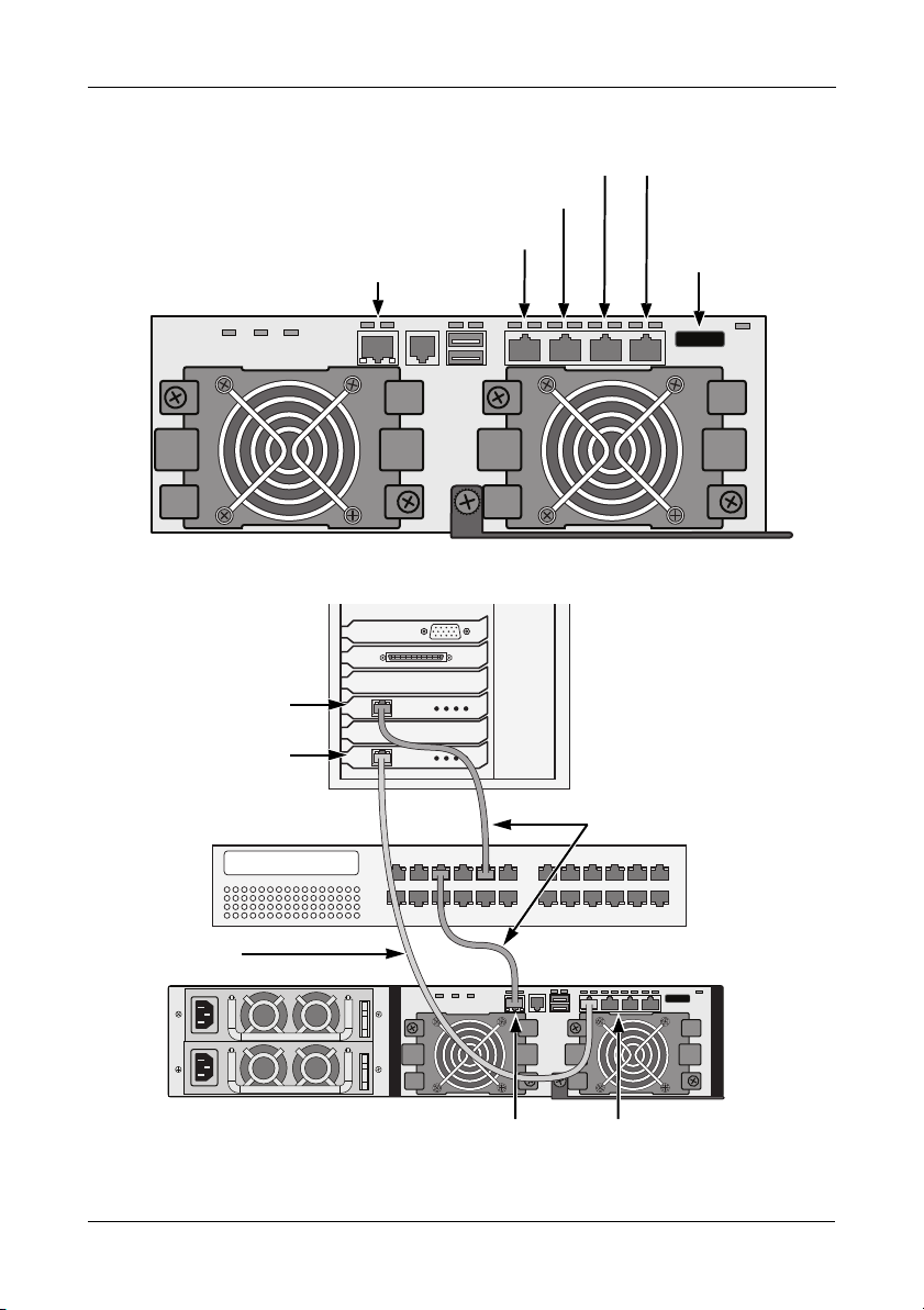
iSCSI Data Port 2
SAS Expansion
Port (to JBOD)
Management Port
iSCSI Data Port 1
iSCSI Data Port 4
iSCSI Data Port 3
Standard NIC
GbE NIC
Host PC
or Server
Standard Network Switch
VessRAID 1830i+
1830i is similar
Management
Cables
Data Cable
iSCSI Data Ports (4)Management Port
Figure 18.VessRAID 1830i+ data and management ports. 1830i is similar
Figure 19.iSCSI DAS data and management connections
21
Page 22

VessRAID 1000f, 1000i, 1000s Series Quick Start Guide
iSCSI Storage Area Network (SAN)
This arrangement requires:
• A Gigabit Ethernet network interface card (GbE NIC) in the Host PC or
Server with iSCSI support in hardware or in software
• A GbE network switch
• A standard network switch
• A network interface connector on the motherboard or network interface card
(NIC) in the Host PC
Note
These instructions also apply to the iSCSI Ports on VessRAID
Fibre Channel subsystems.
Configuring a Data Path
The VessRAID controller has four (4) Ethernet RJ45 iSCSI Port connectors. See
page 21, Figure 18.
To establish the data path:
1. Attach one end of an Ethernet cable to the GbE (iSCSI) NIC in the Host PC.
Attach the other end of the Ethernet cable to one of the ports on the GbE
network switch. See page 24, Figure 20.
If you have multiple VessRAID subsystems, Host PCs or Servers, repeat
steps 1 and 2 as required.
2. Attach one end of an Ethernet cable to one of the ports on the GbE network
switch.
Attach the other end of the Ethernet cable to one of the four iSCSI ports on
the VessRAID controller.
Only one iSCSI data cable is required between the VessRAID and GbE
network switch. However, you can attach multiple cables to create redundant
data paths.
If you have multiple VessRAID subsystems, Host PCs or Servers, repeat
steps 1 and 2 as required.
See also “SAS JBOD Expansion” on page 27.
22
Page 23

Task 5: Making Data and Management Connections
Configuring a Management Path
VessRAID controller has one (1) Ethernet RJ-45 Management Port connector.
page 21, Figure 18.
See
To establish the management path:
1. Attach one end of an Ethernet cable to the standard NIC in the Host PC.
Attach the other end of the Ethernet cable to one of the ports on the standard
network switch. See page 24, Figure 20.
2. Attach one end of an Ethernet cable to one of the ports on the standard
network switch.
Attach the other end of the Ethernet cable to the Management Port on the
VessRAID subsystem. See Figure 20.
If you have multiple VessRAID subsystems, Host PCs or Servers, repeat
steps 1 and 2 as required.
23
Page 24
VessRAID 1000f, 1000i, 1000s Series Quick Start Guide
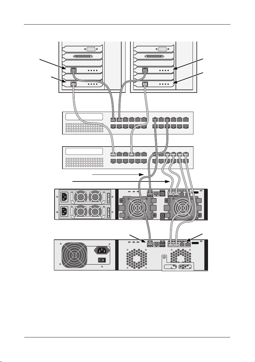
Host PCs or
Servers
Standard
Network
Switch
GbE
Network
Switch
VessRAID 1830i+
VessRAID 1730i
GbE NIC
Standard
NIC
GbE NIC
Management Cables
Data Cables
Standard
NIC
iSCSI Data
Ports (4)
Management Port
Figure 20.iSCSI SAN data and management connections
24
Page 25

Task 5: Making Data and Management Connections
SAS Direct Attached Storage (DAS)
This arrangement requires:
• A standard network switch
• A network interface connector on the motherboard or network interface card
(NIC) in the Host PC
Configuring a Data Path
The VessRAID controller has two (2) SFF-8088 SAS IN Port connectors and one
(1) SFF-8088 SAS Expansion Port connector. See
To establish the data path:
1. Attach one end of a SAS data cable to the SAS HBA card in the Host PC.
See page 26, Figure 22.
2. Attach the other end of the SAS data cable to one of the SAS ports on the
VessRAID subsystem.
See also “SAS JBOD Expansion” on page 27.
Configuring a Management Path
The VessRAID controller has one (1) Ethernet RJ-45 Management Port
connector. See
To establish the management path:
1. Attach one end of an Ethernet cable to the network connector or standard
NIC in the Host PC.
Attach the other end of the Ethernet cable to one of the ports on the standard
network switch.
See page 26, Figure 22.
2. Attach one end of an Ethernet cable to one of the ports on the standard
network switch.
Attach the other end of the Ethernet cable to the Management Port on the
VessRAID subsystem.
If you have multiple VessRAID subsystems, Host PCs or Servers, repeat
steps 1 and 2 as required.
page 26, Figure 21.
page 26, Figure 21.
25
Page 26

VessRAID 1000f, 1000i, 1000s Series Quick Start Guide
SAS IN Port 1 SAS Expansion
Port (to JBOD)
Management port
SAS IN Port 2
Host PC or Server Network Switch
Management
Cables
Management PortData Cable
NIC
SAS HBA card
VessRAID 1830s+
SAS IN Port 1
Figure 21.VessRAID 1830s+ data and management ports. 1830s is similar
Figure 22.SAS DAS data and management connections
26
Page 27

Task 5: Making Data and Management Connections
SAS JBOD Expansion
This arrangement requires:
• One (1) or more VessJBOD expansion subsystems
• One (1) SFF-8088 to SFF-8088 SAS cable for each VessJBOD expansion
subsystem
Configuring the Data Path
All 16-bay and 12-bay VessRAID subsystems have one (1) SFF-8088 SAS
Expansion Port connector.
To expand the data path:
1. Attach one end of a SFF-8088 to SFF-8088 SAS cable to the SAS
Expansion Port on the VessRAID subsystem.
See page 28, Figure 23.
2. Attach the other end of the SFF-8088 to SFF-8088 SAS cable to the SAS IN
Port on the VessJBOD subsystem.
If you have another VessJBOD subsystem, attach one end of the SFF-8088
to SFF-8088 SAS cable to the SAS OUT Port of the first VessJBOD to the
SAS IN Port of the second VessJBOD.
Important
VessJBOD subsystems have one SAS IN port and one SAS OUT
port. If you connect them incorrectly, the VessRAID does not
recognize the VessJBOD subsystems.
For more information, see the
CD that came with the VessJBOD subsystem.
VessJBOD Product Manual
on the
Configuring a Management Path
The VessRAID controller manages the VessJBOD subsystems. No additional
management connections are required for JBOD expansion.
27
Page 28

VessRAID 1000f, 1000i, 1000s Series Quick Start Guide
VessRAID 1830i
VessJBOD 1830+
SAS Expansion Port
SAS OUT Port
SAS IN Port
VessJBOD 1730
SAS data cable
Figure 23.SAS JBOD expansion data connections
After you complete your data and management connection, go to “Task 6: Setting
Up Serial Cable Connections” on page 29.
28
Page 29
Task 6: Setting Up Serial Cable Connections
RJ11 Serial Connector
RJ11 Serial Connector
RJ11 Serial Connector
Task 6: Setting Up Serial Cable Connections
Serial communication enables the Command Line Interface (CLI) and Command
Line Utility (CLU) on your PC to monitor and control the VessRAID. The
VessRAID package includes a RJ11-to-DB9 serial data cable.
Figure 24. Serial connector on an FC controller
Figure 25. Serial connector on an iSCSI controller
Figure 26. Serial connector on a SAS controller
To set up a serial cable connection:
1. Attach the RJ11 end of the serial data cable to the RJ11 serial connector on
the controller.
2. Attach the DB9 end of the serial data cable to a serial port on the Host PC or
Server.
This completes the serial cable connection. Go to “Task 7: Connecting the
Power” on page 30.
29
Page 30
VessRAID 1000f, 1000i, 1000s Series Quick Start Guide
Power
Controller Activity
Global Enclosure Status
Global RAID Status
Reserved
System Heartbeat
Task 7: Connecting the Power
Plug-in the power cords and turn on the switches on both power supplies.
Important
If you have a SAN, DAS, or Cascade with JBOD Expansion,
always power on the JBOD subsystems first.
When the power is switched on, the LEDs and LCD screen light up.
Front Panel LEDs
When boot-up is finished and the VessRAID subsystem is functioning normally:
• Power, Global Enclosure Status, and Global RAID Status LEDs display
green continuously.
• Controller Activity LED flashes green when there is controller activity.
• System Heartbeat LED blinks green seven times in three seconds, goes
dark for six seconds, then repeats the pattern.
Figure 27.VessRAID front panel LED display
Controller LEDs
When boot-up is finished and the VessRAID subsystem is functioning normally:
• Battery, and Controller status LEDs display green continuously.
• Ethernet LEDs display green or flash depending on your network
connection.
30
Page 31

Task 7: Connecting the Power
Dirty Cache
Fan 2
Fan 1
Battery
USB 2
USB 1
Controller Status
JBOD Expansion
16- and 12-bay
subsystems
iSCSI
1 2
FC Ports
12
Fan 2Fan 1
Dirty Cache
Fan 2
Fan 1
Battery
USB 2
USB 1
Controller Status
iSCSI Ports
1 2 3 4
JBOD Expansion
16- and 12-bay
subsystems
Fan 2Fan 1
• The FC, iSCSI, SAS, and Expansion LEDs display green or flash during port
activity.
Figure 28.VessRAID 1840f+ controller LEDs. 1840f is similar
Figure 29.VessRAID iSCSI Controller LEDs
31
Page 32

VessRAID 1000f, 1000i, 1000s Series Quick Start Guide
Dirty Cache
Fan 2
Fan 1
Battery
USB 2
USB 1
Controller Status
SAS IN Port 2
SAS IN Port 1
JBOD Expansion
16- and 12-bay
subsystems
Fan 2Fan 1
Disk Status
Power/Activity
Disk Status
Power/Activity
Plus carrier
Original carrier
Figure 30.VessRAID SAS Controller LEDs
Disk Drive LEDs
There are two LEDs on each Drive Carrier. They report the presence of a disk
drive, activity of the drive, and the drive’s current condition.
Figure 31.VessRAID drive carrier LEDs
If there is a disk drive in the carrier, the Power/Activity LED displays Green. If not,
the Power/Activity LED remains dark. The Power/Activity LED flashes during
drive activity.
The Disk Status LED displays Green when a drive is configured.
32
Page 33

Task 7: Connecting the Power
LCD Panel
The LCD panel activates approximately 35 seconds after you switch on the
VessRAID’s power supply.
At first, the LCD screen displays
When the VessRAID is fully booted and running under normal conditions, the
LCD screen shows the VessRAID model number and IP address, as shown in
Figure 32.
System is Initializing
.
Figure 32.VessRAID optional LCD display
A list of LCD panel functions and instructions for using them is included in the
VessRAID Product Manual
This completes the power and start-up. Go to “Task 8: Setting the IP Address” on
page 34.
on the CD.
33
Page 34

VessRAID 1000f, 1000i, 1000s Series Quick Start Guide
Task 8: Setting the IP Address
Setting up the Serial Connection
VessRAID has a Command Line Interface (CLI) to manage all of its functions,
including customization. A subset of the CLI is the Command Line Utility (CLU), a
user-level interface that manages your VessRAID via your PC’s terminal
emulation program, such as Microsoft HyperTerminal. This procedure uses the
serial cable connection you made in Task 5 (see
You must use the CLI, the CLU, or the optional LCD to assign an IP address to
the VessRAID to enable a network connection for WebPAM PROe.
1. Change your terminal emulation program settings to match the following
specifications:
• Bits per second: 115200
• Data bits: 8
• Parity: None
• Stop bits: 1
• Flow control: none
2. Start your PC’s terminal VT100 or ANSI emulation program.
3. Press Enter once to launch the CLI.
4. At the Login prompt, type administrator and press Enter.
5. At the Password prompt, type password and press Enter.
At this point, you are in the CLI.
You can continue using the CLI to make network settings. See the
Product Manual
Or you can switch to Setting up with the CLU (page 36)
for more information.
page 29).
VessRAID
Choosing DHCP or a Static IP Address
When you setup your VessRAID, you have the option of:
• Enabling DHCP and letting your DHCP server assign the IP address to the
VessRAID’s management port.
• Specifying a static IP address for the VessRAID’s management port.
If you choose to enable DHCP, have your Network Administrator dedicate an IP
address for the VessRAID, linked to the VessRAID’s MAC address. This action
will prevent the DHCP server from assigning a new IP address when the
VessRAID restarts, with the result that users can no longer log in.
34
Page 35

Task 8: Setting the IP Address
MAC Address
To access the MAC address for VessRAID’s management port:
1. At the administrator@cli> prompt, type menu and press Enter.
The CLU main menu appears.
2. In the CLU Main Menu, highlight
Network Management
and press Enter,
then highlight the management port and press Enter
Figure 33.Viewing the management port’s MAC address.
35
Page 36

VessRAID 1000f, 1000i, 1000s Series Quick Start Guide
Setting up with the CLU
1. At the administrator@cli> prompt, type menu and press Enter.
The CLU main menu appears.
Figure 34.CLU main menu
2. With
Quick Setup
The first Quick Setup screen enables you to make Date and Time settings.
highlighted, press Enter.
Setting system date and time
To make date and time settings:
1. Press the arrow keys to highlight
2. Press the backspace key to erase the current date.
3. Type the new date.
4. Follow the same procedure to set the System Time.
5. Press Ctrl-A to save these settings and move to the Management Port
configuration screen.
System Date
.
Making Manual IP Settings
To make Management Port and iSCSI Port settings manually:
1. Press the arrow keys to highlight
2. Press the backspace key to erase the current IP Address.
IP Address
36
.
Page 37

Task 8: Setting the IP Address
3. Type the new IP Address.
4. Follow the same procedure to specify the Subnet Mask, Gateway IP
Address and DNS Server IP Address.
If you do not have a DNS server, skip the DNS Server IP address.
5. Press Ctrl-A to save these settings and move to the RAID configuration
screen.
Making Automatic IP Settings
To make Management Port and iSCSI Port settings automatically:
1. Press the arrow keys to highlight
2. Press the spacebar to toggle to
3. Press Ctrl-A to save these settings and move to the RAID configuration
screen.
DHCP
Enable.
.
Configuring the RAID
You can configure your RAID arrays and logical drives using the CLU at this time.
However, those actions are described in
WebPAM PROe” on page 40. PROMISE suggests that you highlight
Step and Finish
PRO.
and press Enter. Then create your disk array using WebPAM
“Task 9: Creating Logical Drives with
Skip the
Viewing IP Address and Settings
To view the current IP address and network settings when using DHCP:
1. In the CLU Main Menu, highlight
2. Highlight the Management Port or iSCSI Port you want and press Enter.
3. Highlight
The current Management or iSCSI Port settings are displayed.
4. Press the spacebar to toggle DHCP back to
5. Press Ctrl-A to save these settings and move to the RAID configuration
screen.
DHCP
and press the spacebar to toggle to
Network Management
Disable
Enable
.
and press Enter.
.
Exiting the CLU
In the CLU Main Menu, highlight
This completes the Management Port setup.
Go to “Task 9: Creating Logical Drives with WebPAM PROe” on page 40.
Return to CLI
and press Enter.
Setting up with the LCD
The LCD Panel displays the current IP address during normal operation. If you
did not install the LCD Panel, see
page 7. The LCD does not have a date and time function.
“Task 2: Installing the LCD Panel (Optional)” on
37
Page 38

VessRAID 1000f, 1000i, 1000s Series Quick Start Guide
Figure 35.LCD Panel default view
Making Manual IP Settings
To make Management Port settings manually:
1. Press the or button until the display says
2. Press the button and the display says
If it says
3. Press the or button and the display says
4. Press the button to make a change.
The current IP Address displays with the cursor under the first (extreme left)
digit.
5. Press the button to increment and the button decrement.
Press the button to move left and the button to move right.
To set an IP address with double- or single-digit octets, for example,
192.168.1.50, type zeros as placeholders, 192.168.001.050.
After you have set the last (extreme right) digit, press the button.
The current Subnet Mask displays with the cursor under the first (extreme
left) digit.
6. Make the needed changes the same as in step 5.
After you have set the last (extreme right) digit, press the button.
The current Gateway displays with the cursor under the first (extreme left)
digit.
7. Make the needed changes the same as in step 5.
After you have set the last (extreme right) digit, press the button.
The display says
8. Press the button to confirm.
The display shows the new IP address you set.
Link Status Down
Save Network Setting?
, reconnect to the network before preceding.
Management Port
Link Status Up
IP Address.
.
.
38
Page 39

Task 8: Setting the IP Address
Making Automatic IP Settings
To make Management Port settings automatically:
1. Press the or button until the display says
2. Press the button and the display says
If it says
Link Status Down
, reconnect to the network before preceding.
3. Press the or button and the display says
4. Press the button to make a change.
5. Press the button to Enable.
6. Press the button to confirm.
The display shows the new IP address set by the DHCP server.
This completes the Management Port setup.
Management Port
Link Status Up
DHCP Disable.
.
.
39
Page 40

VessRAID 1000f, 1000i, 1000s Series Quick Start Guide
Task 9: Creating Logical Drives with WebPAM PROe
Setting up WebPAM PROe consists of the following actions:
• Logging into WebPAM PROe (below)
• Choosing a Language (page 41)
• Creating Your Logical Drives (page 42)
• Logging out of WebPAM PROe (page 46)
• Using WebPAM PROe over the Internet (page 46)
Logging into WebPAM PROe
1. Launch your Browser.
2. In the Browser address field, type the IP address of the VessRAID
subsystem.
Use the IP address you obtained in Task 7 (see page 36). Note that the IP
address shown below is only an example. The IP address you type into your
browser will be different.
Regular Connection
• WebPAM PROe uses an HTTP connection. . . . . . . . . . . . . . . .http://
• Enter the VessRAID’s IP address . . . . . . . . . . . . . . . 192.168.10.85
Together, your entry looks like this:
http://192.168.10.85
Secure Connection
• WebPAM PROe uses a secure HTTP connection . . . . . . . . . .https://
• Enter the VessRAID’s IP address . . . . . . . . . . . . . . . 192.168.10.85
Together, your entry looks like this:
https://192.168.10.85
Note
Whether you choose a regular or a secure connection, your login
to WebPAM PROe and your user password are always secure.
3. When the log-in screen appears:
•Type administrator in the User Name field.
•Type password in the Password field.
• Click the Login button.
The User Name and Password are case sensitive
40
Page 41

Task 9: Creating Logical Drives with WebPAM PROe
Figure 36.WebPAM PROe log-in screen
After sign-in, the WebPAM PROe opening screen appears. If there are any
unconfigured physical drives in the enclosure, an Array Configuration menu also
appears. See
page 42, Figure 38.
Note
Make a Bookmark (Firefox) or set a Favorite (Internet Explorer) of
the Login Screen so you can access it easily next time.
Choosing a Language
WebPAM PROe displays in English, German, French, Italian, Japanese, Korean,
Traditional Chinese, and Simplified Chinese.
1. Click Language on the WebPAM PROe Header.
The language list appears in the Header.
2. Click the language you prefer.
The WebPAM PROe user interface displays in the chosen language.
41
Page 42

VessRAID 1000f, 1000i, 1000s Series Quick Start Guide
Figure 37.Clicking “Language” on the WebPAM PROe Header
Creating Your Logical Drives
On a newly activated VessRAID subsystem, there are no disk arrays or logical
drives. To create a logical drive:
1. Click the Disk Arrays icon, then click the Create tab.
The Array Configuration menu appears.
Figure 38.The Array Configuration menu
2. Choose one of the options:
• Automatic – Creates a new disk array following a default set of
parameters. Makes one logical drive automatically. Also makes a hot
spare drive for all RAID levels except RAID 0, if at least four
unconfigured physical drives are available. See page 43.
• Express – You choose the parameters for a new disk array by
specifying the characteristics you want. You can create multiple logical
drives at the same time, however they will all be identical. You can
choose to make a hot spare drive for all RAID levels except RAID 0, if at
least four unconfigured physical drives are available. See page 43.
• Advanced – You directly specify all parameters for a new disk array.
Makes one logical drive automatically. You can create additional logical
drives at a later time, if additional configurable capacity is available.
Does not make a hot spare drive. See page 44.
3. Click the Next button.
42
Page 43

Task 9: Creating Logical Drives with WebPAM PROe
Automatic
When you choose the Automatic option, the following parameters appear on the
screen:
• Disk Arrays – The number of physical drives in the disk array, their ID
numbers, configurable capacity, and the number of logical drives to be
created
• Logical Drives – The ID number of the logical drive(s), their RAID level,
capacity, and stripe size
• Spare Drives – The physical drive slot number of the dedicated hot spare
assigned to this disk array. A hot spare drive is created for all RAID levels
except RAID 0, when five or more unconfigured physical drives are available
If you accept these parameters, click the Submit button.
The new disk array appears in the Disk Array List on the Information tab.
If you do NOT accept these parameters, use the Express (below) or Advanced
page 44) option to create your logical drive.
(
Express
When you choose the Express option, a set of characteristics and options
appears on the screen.
1. Check the boxes to choose any one or a combination of:
• Redundancy – The array will remain available if a physical drive fails
• Capacity – The greatest possible amount of data capacity
• Performance – The highest possible read/write speed
• Spare Drive – A hot spare drive is created when you choose
Redundancy, Spare Drive, and five or more unconfigured physical
drives are available
• Mixing SATA/SAS Drive – Check this box if you want to use both SATA
and SAS drives in the same disk array
If the box is unchecked, and you have both SATA and SAS drives,
different arrays will be created for each type of drive.
2. In the Number of Logical Drives field, enter the number of logical drives you
want to make from this disk array.
The maximum possible number of logical drives appears to the right of this
field.
3. From the Application Type menu, choose an application that best describes
your intended use for this disk array:
•File Server
• Video Stream
• Transaction Data
• Transaction Log
• Other
43
Page 44

VessRAID 1000f, 1000i, 1000s Series Quick Start Guide
4. Click the Update button.
Or check the Automatic Update box and updates will occur automatically.
The following parameters display:
• Disk Arrays – The number of physical drives in the disk array, their slot
numbers, configurable capacity, and the number of logical drives to be
created
• Logical Drives – The slot number of the logical drive(s), their RAID
level, capacity, and stripe size
• Spare Drives – The physical drive slot number of the dedicated hot
spare assigned to this disk array (all RAID levels except RAID 0)
If you accept these parameters, proceed to the next step.
If you do NOT accept these parameters, review and modify your selections
in the previous steps.
5. When you are done, click the Submit button.
The new disk array appears in the Disk Array List on the Information tab.
Advanced
For an explanation of the parameters under the Advanced option,
see the
VessRAID Product Manual
Note
on the CD.
When you choose the Advanced option, the
Step 1 – Disk Array Creation
screen
displays.
Step 1 – Disk Array Creation
1. Optional. Enter a name for the disk array in the field provided.
Maximum of 31 characters; letters, numbers, space between characters, and
underline.
2. Uncheck the boxes if you want to disable Media Patrol or PDM.
PROMISE recommends leaving these features enabled.
3. Highlight physical drives you want in the disk array from the Available list and
press the >> button to move them to the Selected list.
You can also double-click them to move them.
4. When you are done, click the Next button.
Step 2 – Logical Drive Creation
1. Optional. Enter an alias for the logical drive in the field provided.
Maximum of 31 characters; letters, numbers, space between characters, and
underline.
44
Page 45

Task 9: Creating Logical Drives with WebPAM PROe
2. Choose a RAID level for the logical drive from the dropdown menu.
The choice of RAID levels depends the number of physical drives you
selected.
3. RAID 50 and 60 only – Specify the number of axles for your array.
4. Specify a Capacity and the unit of measure (B, KB, MB, GB, TB).
This value will be the data capacity of the first logical drive in your new disk
array. If you specify less than disk array's maximum capacity, the remaining
capacity is available for additional logical drives that you can create now or
later.
5. For the following items, accept the default or choose a new value from the
dropdown menu:
• Stripe size. 128 KB is the default.
64 KB, 128 KB, 256 KB, 512 KB, and 1 MB are available.
• Sector size. 512 B is the default.
512 B, 1 KB, 2 KB, and 4 KB are available.
• Read (cache) Policy. Read Ahead is the default.
Read Cache, Read Ahead Cache, and No Cache are available.
• Write (cache) Policy. Write Back is the default.
Write Back and Write Through (Thru) are available.
6. Click the Update button.
A new logical drive is displayed under New Logical Drives. If there is free
capacity remaining, you can specify another logical drive now or wait until
later.
7. When you are done specifying logical drives, click the Next button.
Step 3 – Summary
The Summary lists the disk array and logical drive information you specified.
To proceed with disk array and logical drive creation, click the Submit button.
Note
This function does not automatically create a hot spare drive. After
the disk array is created, you can create a hot spare drive for it.
See the
VessRAID Product Manual
45
on the CD.
Page 46

VessRAID 1000f, 1000i, 1000s Series Quick Start Guide
Logging out of WebPAM PROe
There are two ways to log out of WebPAM PROe:
• Close your browser window
•Click Logout on the WebPAM PROe banner
Figure 39..Clicking “Logout” on the WebPAM PROe banner
Clicking Logout brings you back to the Login Screen. See page 40.
After logging out, you must enter your user name and password in order to log in
again.
Using WebPAM PROe over the Internet
The above instructions cover connections between VessRAID and your company
network. It is also possible to connect to a VessRAID from the Internet.
Your MIS Administrator can tell you how to access your network from outside the
firewall. Once you are logged onto the network, you can access the VessRAID
using its IP address.
46
Page 47

Contacting Technical Support
Contacting Technical Support
PROMISE Technical Support provides several support options for PROMISE
users to access information and updates. We encourage you to use one of our
electronic services, which provide product information updates for the most
efficient service and support.
If you decide to contact us, please have the following information available:
• Product model and serial number
• BIOS, firmware and driver version numbers
• A description of the problem or situation
• System configuration information, including: motherboard and CPU type,
hard drive models, SAS/SATA/ATA/ATAPI drives & devices, and other
controllers.
Technical Support Services
PROMISE Online™ Website http://www.promise.com/support/
support_eng.asp
(technical documents, drivers, utilities, etc.)
E-mail Support e-Support On-Line
Phone Support:
United States +1 408 228 1400 option 4
The Netherlands +31 0 40 235 2600
Germany +49 (0) 2 31 56 76 48 - 0
Italy +39 0 6 367 126 26
Japan +81 03 6801 8063
Taiwan +886 3 578 2395 ext. 8845
Beijing, China +86 10 8857 8085 or 8095
Shanghai, China +86 21 6249 4192, 4193, or 4199
47
Page 48

VessRAID 1000f, 1000i, 1000s-Serie Kurzanleitung
VessRAID Arbeitsschritte
• Schritt 1: Auspacken des VessRAID (Seite 48)
• Schritt 2: Installieren des LCD Panels (Optional) (Seite 53)
• Schritt 3: Montage des VessRAID in einem Rack (Seite 55)
• Schritt 4: Einbauen der Festplatten (Seite 58)
• Schritt 5: Aufsetzen von Daten- und V
• Schritt 6: Anschließen der seriellen Kabelverbindungen (Seite 76)
• Schritt 7: Anschließen der Stromversorgung (Seite 77)
• Schritt 8: Einstellen der IP-Adresse (Seite 82)
• Schritt 9: Erstellen von logischen Laufwerken mit WebPAM PROe (Seite 89)
• Kontaktaufnahme mit dem Technischen Support (Seite 97)
Schritt 1: Auspacken des VessRAID
Das VessRAID-Paket enthält folgende Komponenten:
• VessRAID-Gerät
•
Kurzanleitung
• Serielles Datenkabel, RJ11 auf DB9
• Schrauben für Festplatten
(70 Stück für 16-Schacht,
50 Stück für 12- und 8-Schacht)
gedruckt
erwaltungsverbindungen (Seite 61)
• Stromkabel 1,5 m
(1700 Modelle, 1;
1800 Modelle, 2)
• CD mit SNMP-Dateien,
Produkthandbuch
Kurzanleitung
PDF-format
im
und
Eine Battery Backup Unit (BBU) ist für das V
vorgesehen. Im Falle eines Ausfalls der Stromversorgung liefert die BBU Strom
an den Controllercache, um die darin enthaltenen Daten zu erhalten.
Das ist ein Klasse A-Produkt. In einer häuslichen Umgebung kann
dieses Produkt möglicherweise Störungen beim Radio- und
Fernsehempfang verursachen, wobei das Ergreifen angemessener
Maßnahmen seitens des Benutzers ggf. erforderlich ist.
essRAID-Subsystem optional
Warnung
48
Page 49

Schritt 1: Auspacken des VessRAID
Warnung
Die elektronischen Komponenten im V
essRAID-Gehäuse können
durch elektrostatische Entladung (ESD) Schaden nehmen.
Beachten Sie stets die entsprechenden Vorsichtsmaßnahmen,
wenn Sie das VessRAID oder seine Bauteile handhaben.
Vorsichtshinweis
•
Falls Sie eine Batterie durch einen falschen Batterietyp
ersetzen, besteht Explosionsgefahr.
• Entsorgen Sie gebrauchte Batterien entsprechend den der
Batterie beiliegenden Anweisungen.
VessRAID Modellreihe
Anzahl
Modell Schnittstelle
der
Laufwerke
1840f+ Fibre Channel 16 plus 2 extern
1840f Fibre Channel 16 ursprünglich 2 intern
1840i+ iSCSI 16 plus 2 extern
1840i iSCSI 16 ursprünglich 2 intern
Festplatten-
träger
Netzteile Controller-
Lüfter
1840s+ SAS 16 plus 2 extern
1840s SAS 16 ursprünglich 2 intern
1830i+ iSCSI 12 plus 2 extern
1830i iSCSI 12 ursprünglich 2 intern
1830s+ SAS 12 plus 2 extern
1830s SAS 12 ursprünglich 2 intern
1820i iSCSI 8 ursprünglich 2 intern
1740i iSCSI 16 ursprünglich 1 intern
49
Page 50

VessRAID 1000f, 1000i, 1000s-Serie Kurzanleitung
Festplattenträger-LEDs
Festplattenträger
Betriebs- und Statusanzeige-LEDs
Festplattenträger-LEDs
Festplattenträger Betriebs- und Statusanzeige-LEDs
1740s SAS 16 ursprünglich 1 intern
1730i
iSCSI 12 ursprünglich 1 intern
1730s SAS 12 ursprünglich 1 intern
1720i+ iSCSI 8 plus 1 extern
1720i iSCSI 8 ursprünglich 1 intern
Abbildung 1. 12-Schacht VessRAID mit dem „ursprünglichen“
Festplattenträger-Design
Abbildung 2. 12-Schacht VessRAID mit dem „plus“
Festplattenträger-Design
Ein defektes Laufwerk kann ohne Unterbrechung der Datenverfügbarkeit im
Hostcomputer ersetzt werden. Bei einer entsprechenden Konfiguration ersetzt
ein redundantes Ersatzlaufwerk automatisch das ausgefallene Laufwerk, was
sicherstellt, dass das logische Laufwerk auch bei bestimmten Fehlern zur
Verfügung steht. Das unabhängige, hardwarebasierte, logische RAID-Laufwerk
bietet in einem kompakten externen Gehäuse maximale Leistung.
50
Page 51

Schritt 1: Auspacken des VessRAID
Externe Lüfter
SAS RAID-ControllerDoppelte Netzteile
SAS RAID-ControllerDoppelte Netzteile
Externe Lüfter
iSCSI RAID-Controller
Interne Lüfter
Doppelte Netzteile
Abbildung 3. VessRAID 1840f+ Rückansicht
Abbildung 4. VessRAID 1830s+ Rückansicht
Abbildung 5. VessRAID 1830i Rückseitenansicht
51
Page 52

VessRAID 1000f, 1000i, 1000s-Serie Kurzanleitung
Interne Lüfter
SAS RAID-ControllerEinzelnes Netzteil
Abbildung 6. VessRAID 1730s Rückansicht
Weitere Beschreibungen zu den LEDs finden Sie auf Seiten 77 und 79.
52
Page 53

Schritt 2: Installieren des LCD Panels (Optional)
Anschluss auf
dem LCD-Panel
Anschluss auf
dem Gehäuse
Schritt 2: Installieren des LCD Panels (Optional)
Vorsichtshinweise
• Das LCD Panel kann NICHT während des laufenden Betriebs
ausget
auscht werden. Stellen Sie sicher, dass das VessRAID
ausgeschaltet ist, bevor Sie das LCD Panel anschließen oder
trennen.
• Das LCD Panel muss installiert werden, bevor Sie das
V
essRAID-Subsystem in einem Rack montieren.
Das LCD Panel wird in der linken Seite der Halterung des VessRAID-Gehäuses
montiert.
1. Richten Sie den Anschluss auf der linken Halterung des
essRAID-Gehäuses passend zum Anschluss auf der Rückseite des LCD
V
Panels aus, wie in Abbildung 7 gezeigt.
Abbildung 7. Richten Sie die Anschlüsse auf dem Gehäuse und auf dem
LCD Panel zueinander passend aus
2. Führen Sie die zwei Befestigungsschrauben durch die Löcher der linken
Halterung hindurch und in die Gewindelöcher im LCD Panel, wie in gezeigt
Abbildung 8.
Ziehen Sie zur Befestigung des LCD Panels an der Halterung die Schrauben
fest.
53
Page 54

VessRAID 1000f, 1000i, 1000s-Serie Kurzanleitung
Abbildung 8. Anbringen des LCD Panels am VessRAID-Gehäuse
Der LCD Bildschirm wird aktiviert, wenn das VessRAID hochgefahren wird.
Siehe Schritt 7: Anschließen der Stromversorgung auf Seite 77.
Gehen Sie zu Schritt 3: Montage des V
54
essRAID in einem Rack auf Seite 55.
Page 55

Schritt 3: Montage des VessRAID in einem Rack
Schritt 3: Montage des VessRAID in einem Rack
Vorsichtshinweise
• Es werden mindestens zwei Personen benötigt, um das
essRAID-Gerät sicher in das Racksystem zu heben
V
und einzubauen.
• Heben Sie oder bewegen Sie das VessRAID-Gerät nicht
mithilfe der Grif
Halten Sie das Subsystem selbst fest.
• Installieren Sie das VessRAID-Gerät nicht ohne Schienen, die
System unterstützen.
• Das VessRAID-Gerät darf nur von einem mit dem
Inst
allationsvorgang vertrauten, qualifizierten Techniker
montiert und installiert werden.
• Stellen Sie sicher, dass alle Schalter auf OFF (AUS)
geschaltet sind, bevor Sie das V
oder Komponenten austauschen.
• Befestigen Sie die Schienen am Rack, indem Sie sie mithilfe
der ent
sprechenden Schrauben und Flanschmuttern an
jedem Ende der Schienen fest anziehen.
• Belasten Sie die Schienen erst nach ordnungsgemäßer
Mont
age der Schrauben.
• Die im Lieferumfang des PROMISE VessRAID-Geräts
enthaltenen Schienen wurden für die sichere Unterstützung
des PROMISE V
ordnungsgemäßen Installation entwickelt. Bei einer
übermäßigen Belastung der Schienen geht das Risiko
auf den Kunden über.
• PROMISE Technology, Inc. übernimmt nur dann die Garantie
dafür
, dass die Montageschienen Ihr PROMISE
VessRAID-Gerät tragen, wenn die Schienen ordnungsgemäß
montiert wurden.
fe, Netzteile oder der Controllerkomponenten.
essRAID-Gerät installieren
essRAID-Geräts nach einer
Anmerkung
Um das Gewicht des VessRAID-Gehäuses zu reduzieren,
ent
fernen Sie die Stromversorgungseinheiten. Setzen Sie die
Stromversorgungseinheiten wieder ein, sobald sich das
VessRAID-Gerät wieder im Rack befindet.
Das VessRAID-Subsystem wird mit den mitgelieferten Montageschienen im Rack
montiert. Es können auch eigene vorhandene Schienen verwendet werden.
55
Page 56

VessRAID 1000f, 1000i, 1000s-Serie Kurzanleitung
Vertikaler Rackpfosten VessRAID-Subsystem
Montageschienen
werden außen am
Rackpfosten montiert
Griffe zur Befestigung
an der Außenseite
der Rackpfosten
Abbildung 9.
in einem Rack montiert
Ein 16-Schacht-VessRAID mit den mitgelieferten Schienen
So installieren Sie das VessRAID-Subsystem mit den mitgelieferten
Montageschienen in einem Rack:
1. Prüfen Sie, ob die Montageschienen einwandfrei in Ihr Racksystem passen.
Siehe Seite 57, Abbildung 10.
2. Passen Sie die Länge der Montageschienen erforderlichenfalls an.
Die hintere Schiene gleitet in der vorderen Schiene. Die Schienenhälf
ten
sind miteinander vernietet und benötigen keine Einstellschrauben.
3. Befestigen Sie die Montageschiene an der Außenseite der Rackp
fosten;
verwenden Sie dazu die Befestigungsschrauben und die Flanschmuttern
Ihres Racksystems.
Achten Sie darauf, dass die Auflage der vorderen Schiene unten ist und
nach innen zeigt.
Die Ausrichtungsstif
te passen in die Racklöcher ober- und unterhalb der
Befestigungsschrauben.
Verwenden Sie die Befestigungsschrauben und Flanschmuttern Ihres
Racksystems. Ziehen Sie die Schrauben und Flanschmuttern gemäß den
Anweisungen für Ihr Racksystem fest.
4. Platzieren Sie das VessRAID-Subsystem auf den Schienen.
5. Verbinden Sie das VessRAID-Subsystem sicher mit dem Rack.
Eine Schraube auf jeder Seite, nur in der oberen Bohrung. Verwenden Sie
die Befestigungsschrauben und Flanschmuttern Ihres Racksystems.
Ziehen Sie die Schrauben und Flanschmuttern gemäß den Anweisungen
für Ihr Racksystem fest.
56
Page 57

Schritt 3: Montage des VessRAID in einem Rack
Pfosteninnenseite
Vorderer Rackpfosten
Schrauben zur Befestigung der
Schienen (nicht mitgeliefert)
Ausrichtungszapfen
zwei an jedem Flansch
Pfosteninnenseite
Hinterer Rackpfosten
Vordere Schiene Hintere Schiene
Auflage für Subsystem
Beachten Sie, dass nur die vordere Schiene eine Auflage für das Subsystem besitzt.
Abbildung 10. Arbeitsplan für Rackmontage
Damit ist die Rackmontage vollständig abgeschlossen. Gehen Sie zu Schritt 4:
Einbauen der Festplatten auf Seite 58.
57
Page 58

VessRAID 1000f, 1000i, 1000s-Serie Kurzanleitung
Schritt 4: Einbauen der Festplatten
Die VessRAID-Subsysteme und VessJBOD-Erweiterungseinheiten unterstützen:
• SAS- und SATA-Festplattenlaufwerke
• 3,5-Zoll Festplattenlaufwerke
Um eine Liste von unterstützten physikalischen Laufwerken zu erhalten, laden
Sie die neuste Komp
herunter.
Die erforderliche Anzahl von Festplatten
In der nachfolgenden Tabelle wird die erforderliche Anzahl von Festplatten für
jeden RAID-Level angezeigt
atibilitätsliste von der Support-Website von PROMISE
Stufe
RAID 0 1 oder mehr RAID 6 4 bis 32*
RAID 1 nur 2 RAID 10 4 oder mehr**
RAID 1E 2 oder mehr RAID 30 6 oder mehr
RAID 3 3 bis 32* RAID 50 6 oder mehr
RAID 5 3 bis 32* RAID 60 8 oder mehr
* Eine JBOD-Erweiterungseinheit ist eventuell erforderlich.
** Gerade Anzahl von Festplatten erforderlich.
Anzahl der
Laufwerke
Stufe
Anzahl der
Laufwerke
Nummerierung der Laufwerksteckplätze
Sie können jede geeignete Festplatte in einen der Steckplätze des Gehäuses
installieren. Die Darstellung unten zeigt, wie die Laufwerksteckplätze des
VessRAID nummeriert sind. Unabhängig davon, ob Sie die „ursprünglichen“ oder
„plus“-Festplattenträger haben, sind die Steckplätze gleich nummeriert.
Die Steckplatznummerierung spiegelt sich in den Benutzeroberflächen von
ebPAM PROe und CLU wider. Siehe Abbildungen 11, 12 und 13.
W
58
Page 59

Abbildung 11. Nummerierung der 16-Schacht
1
5
9
13
2
6
10
14
3
7
11
15
4
8
12
16
1
5
9
2
6
10
3
7
11
4
8
12
1
5
2
6
3
7
4
8
VessRAID-Laufwerkssteckplätze
Abbildung 12. Nummerierung der 12-Schacht
VessRAID-Laufwerkssteckplätze
Abbildung 13. Nummerierung der 8-Schacht
VessRAID-Laufwerkssteckplätze
Schritt 4: Einbauen der Festplatten
Installieren Sie alle Festplatten-Träger in das VessRAID-Gehäuse, selbst wenn
Sie nicht alle Träger mit Festplatten bestücken. Dies stellt einen
ordnungsgemäßen Luftstrom sicher.
Installieren der Festplattenlaufwerke
So installieren Sie die Festplattenlaufwerke:
1. Entfernen Sie einen Festplattenträger.
2. Legen Sie die Festplatte vorsichtig in einen Festplattenträger auf der
orderseite, so dass die seitlich angebrachten Schraubenlöcher bündig
V
übereinander liegen.
Siehe Seite 60, Abbildung 14.
59
Page 60

VessRAID 1000f, 1000i, 1000s-Serie Kurzanleitung
Festplatte
Montageschraube
Montageschraube
3. Führen Sie die Schrauben durch die Löcher im Festplattenträger und in die
Gewindebohrungen in der Festplatte ein.
• Verwenden Sie nur die mit dem VessRAID mitgelieferten
Senkkop
fschrauben.
• Verwenden Sie vier Schrauben pro Festplatte.
• Drehen Sie jede Schraube fest. Gehen Sie dabei behutsam vor,
um ein Überdrehen der Schrauben zu vermeiden.
4. Schieben Sie den Laufwerkträger wieder in das V
essRAID-Gehäuse ein.
Wiederholen Sie die Schritte 1 bis 3, bis alle Festplatten eingebaut sind.
Abbildung 14. In einem Festplattenträger montierte Festplatte
Damit ist die Festplatteninstallation abgeschlossen. Gehen Sie zu Schritt 5:
Aufsetzen von Daten- und Verwaltungsverbindungen auf Seite 61.
Vorsicht
VessRAID unterstützt den Festplattenaust
ausch bei laufendem
Betrieb („Hot-Swapping“). Um den Handkontakt mit elektrischen
Gefahrenquellen zu vermeiden, entfernen Sie nicht mehr als einen
Festplattenträger auf einmal.
60
Page 61

Schritt 5: Aufsetzen von Daten- und Verwaltungsverbindungen
Schritt 5: Aufsetzen von Daten- und
Verwaltungsverbindungen
Das VessRAID kann konfiguriert werden als:
• Fibre Channel Direct Attached S
• Fibre Channel Storage Area Network (SAN) (Seite 64)
• iSCSI Direct Attached Storage (DAS) (Seite 67)
• iSCSI Storage Area Network (SAN) (Seite 69)
• SAS Direct Attached Storage (DAS) (Seite 72)
• SAS JBOD-Erweiterung (Seite 74)
Um eine Liste von FC HBAs, Switches und SFPs zu erhalten,
laden Sie die neuste Komp
von PROMISE herunter.
Die Kaskadierung mehrerer RAID-Subsysteme wird von
V
essRAID nicht unterstützt. Kaskadierung ist für einen zukünftigen
Release geplant.
Fibre Channel Direct Attached Storage (DAS)
Diese Anordnung erfordert:
• Eine Fibre Channel (FC)-Schnitt
• Mindestens ein FC-Transceiver für jedes V
• Eine NIC-Karte (Netzwerkkarte) im Host-PC
• Ein Standard Netzwerk-Switch
torage (DAS), siehe unten
Wichtig
atibilitätsliste von der Support-Website
stellenkarte im Host-PC
essRAID-Subsystem
Anmerkung
VessRAID Fibre Channel-Subsysteme haben auch (2) Ethernet
RJ45 iSCSI Port-Anschlüsse. Siehe iSCSI Direct Attached
Storage (DAS) auf Seite 67 für Verbindungsanweisungen.
61
Page 62

VessRAID 1000f, 1000i, 1000s-Serie Kurzanleitung
Datenverbindung
Der VessRAID-Controller hat zwei (2) FC-Port-Anschlüsse und ein (1) SFF-8088
SAS Erweiterungsport-Anschluss. Siehe Seite 63, Abbildung 15.
So richten Sie die Datenverbindung ein:
1. Installieren Sie einen FC-Transceiver in den FC-Datenport auf dem
Ve
ssRAID-Controller.
Siehe Seite 64, Abbildung 16.
2. Verbinden Sie den FC-Transceiver auf dem V
Host-PC oder Server.
Siehe auch SAS JBOD-Erweiterung auf Seite 74.
essRAID-Controller mit dem
Verwaltungspfad
Der VessRAID-Controller hat einen (1) Ethernet RJ-45
Verwaltungsport-Anschluss. Siehe Abbildung 15.
So richten Sie den Verwaltungspfad ein:
1. Verbinden Sie ein Ende des Ethernet-Kabels mit dem Netzwerkanschluss
bzw
. der Standard-NIC des Host PCs.
Verbinden Sie das andere Ende des Ethernet-Kabels mit einem der Port
auf dem Standard Netzwerk-Switch.
Siehe Seite 64, Abbildung 16.
2. Verbinden Sie ein Ende des Ethernet-Kabels mit einem der Port
Standard Netzwerk-Switch.
Verbinden Sie das andere Ende des Ethernet-Kabels mit dem
V
erwaltungsport auf dem VessRAID-Subsystem.
Wenn Sie mehrere VessRAID-Subsysteme, Host-PCs oder Server haben,
wiederholen Sie gegebenenfalls Schritte 1 und 2.
s auf dem
s
62
Page 63

Schritt 5: Aufsetzen von Daten- und Verwaltungsverbindungen
iSCSI-Datenport 1
Verwaltungsport
iSCSI-Datenport 2
FC-Datenports 2
FC-Datenport 1
SAS-Erweiterungsport
(zu JBOD)
Abbildung 15. VessRAID 1840f+ Daten- und Verwaltungsports. 1840f ist
ähnlich
63
Page 64

VessRAID 1000f, 1000i, 1000s-Serie Kurzanleitung
NIC
Host-PC oder Server Netzwerk-Switch
VessRAID 1840i+1840i
sind ähnlich
Verwaltungskabel
Datenkabel
FC-Datenports (2)Verwaltungsport
FC-Karte
Abbildung 16. FC DAS-Daten- und Verwaltungsanschlüsse
Fibre Channel Storage Area Network (SAN)
Diese Anordnung erfordert:
• Eine Fibre Channel (FC)-Schnittstellenkarte in jedem Host-PC
• Mindestens ein FC-Transceiver für jedes V
• Eine Netzwerkkarte (NIC) in jedem Host-PC
• Ein Standard Netzwerk-Switch
Anmerkung
VessRAID Fibre Channel-Subsysteme haben auch (2) Ethernet
RJ45 iSCSI Port-Anschlüsse. Siehe iSCSI Storage Area Network
(SAN) auf Seite 69 für Verbindungsanweisungen.
64
essRAID-Subsystem
Page 65

Schritt 5: Aufsetzen von Daten- und Verwaltungsverbindungen
Datenverbindung
Der VessRAID-Controller hat zwei (2) FC Port-Anschlüsse und zwei (2) Ethernet
RJ45 iSCSI-Port-Anschlüsse. Siehe Seite 63, Abbildung 15.
So richten Sie die Datenverbindung ein:
1. Installieren Sie einen FC-Transceiver in den FC-Datenport auf dem
Ve
ssRAID-Controller.
Siehe Seite 66, Abbildung 17.
2. Verbinden Sie den FC-Transceiver auf dem V
FC-Switch.
3. Verbinden Sie den FC-Switch mit der FC HBA-Karte im PC oder Server
Wenn Sie mehrere VessRAID-Subsysteme, Host-PCs oder Server haben,
wiederholen Sie gegebenenfalls Schritte 1 und 2.
Siehe auch SAS JBOD-Erweiterung auf Seite 74.
essRAID-Subsystem mit dem
.
Verwaltungspfad
Der VessRAID-Controller hat einen (1) Ethernet RJ-45
Verwaltungsport-Anschluss. Siehe Seite 63, Abbildung 15.
So richten Sie den Verwaltungspfad ein:
1. Verbinden Sie ein Ende des Ethernet-Kabels mit dem Netzwerkanschluss
bzw
. der Standard-NIC des Host PCs.
Verbinden Sie das andere Ende des Ethernet-Kabels mit einem der Port
auf dem Standard Netzwerk-Switch.
Siehe Seite 66, Abbildung 17.
2. Verbinden Sie ein Ende des Ethernet-Kabels mit einem der Port
Standard Netzwerk-Switch.
Verbinden Sie das andere Ende des Ethernet-Kabels mit dem
V
erwaltungsport auf dem VessRAID-Subsystem.
Wenn Sie mehrere VessRAID-Subsysteme, Host-PCs oder Server haben,
wiederholen Sie gegebenenfalls Schritte 1 und 2.
s auf dem
s
65
Page 66

VessRAID 1000f, 1000i, 1000s-Serie Kurzanleitung
Host-PCs oder
Server
NIC
Netzwerk
-Switch
FC-Switch
VessRAID 1840f+
VessRAID 1840f
FC-Karte
NIC
FC-Karte
Verwaltungskabel
Datenkabel
FC-Datenports (2)Verwaltungsport
Abbildung 17. FC SAN-Daten und Verwaltungsanschlüsse
66
Page 67

Schritt 5: Aufsetzen von Daten- und Verwaltungsverbindungen
iSCSI Direct Attached Storage (DAS)
Diese Anordnung erfordert:
• Eine Gigabit-Ethernet-Netzwerkkarte (GbE NIC) im Host-PC oder Server mit
iSCSI-Unterstützung als Hardware oder Software
• Ein Standard Netzwerk-Switch
• Ein Netzwerkschnittstellenanschluss auf der Hauptplatine oder
Netzwerkkarte (NIC) im Host PC
Anmerkung
Diese Anweisungen beziehen sich auch auf die iSCSI-Port
VessRAID Fibre Channel-Subsystemen.
s auf
Konfigurieren einer Datenverbindung
Der VessRAID-Controller hat vier (4) Ethernet RJ45 iSCSI-Port-Anschlüsse.
Siehe Seite 68, Abbildung 18.
So richten Sie die Datenverbindung ein:
1. Verbinden Sie ein Ende des Ethernet-Kabels mit der GbE (iSCSI) NIC des
Host PCs.
Siehe Seite 68, Abbildung 19.
2. Verbinden Sie das andere Ende des Ethernet-Kabels mit einem der vier
iSCSI-Port
Wenn Sie mehrere VessRAID-Subsysteme, Host-PCs oder Server haben,
wiederholen Sie gegebenenfalls Schritte 1 und 2.
Siehe auch SAS JBOD-Erweiterung auf Seite 74.
s auf dem VessRAID-Controller.
Konfigurieren eines Verwaltungspfads
Der VessRAID-Controller hat einen (1) Ethernet RJ-45
Verwaltungsport-Anschluss. Siehe Seite 68, Abbildung 18.
So richten Sie den Verwaltungspfad ein:
1. Verbinden Sie ein Ende des Ethernet-Kabels mit dem Netzwerkanschluss
. der Standard-NIC des Host PCs.
bzw
Verbinden Sie das andere Ende des Ethernet-Kabels mit einem der Port
auf dem Standard Netzwerk-Switch. Siehe Seite 68, Abbildung 19.
2. Verbinden Sie ein Ende des Ethernet-Kabels mit einem der Port
Standard Netzwerk-Switch.
Verbinden Sie das andere Ende des Ethernet-Kabels mit dem
V
erwaltungsport auf dem VessRAID-Subsystem.
Wenn Sie mehrere VessRAID-Subsysteme, Host-PCs oder Server haben,
wiederholen Sie gegebenenfalls Schritte 1 und 2.
s auf dem
s
67
Page 68

VessRAID 1000f, 1000i, 1000s-Serie Kurzanleitung
iSCSI-Datenport 2
SAS-Erweiterungsport
(zu JBOD)
Verwaltungsport
iSCSI-Datenport 1
iSCSI-Datenport 4
iSCSI-Datenport 3
Standard-NIC
GbE-NIC
Host-PC oder
Server
Standard Netzwerk-Switch
VessRAID 1830i+1830i
sind ähnlich
Verwaltungskabel
Datenkabel
iSCSI-Datenports (4)Verwaltungsport
Abbildung 18. VessRAID 1830s+ Daten- und Verwaltungsports. 1830s ist
ähnlich
Abbildung 19. iSCSI DAS-Daten- und Verwaltungsanschlüsse
68
Page 69

Schritt 5: Aufsetzen von Daten- und Verwaltungsverbindungen
iSCSI Storage Area Network (SAN)
Diese Anordnung erfordert:
• Eine Gigabit-Ethernet-Netzwerkkarte (GbE NIC) im Host-PC oder Server mit
iSCSI-Unterstützung als Hardware oder Software
• Ein GbE Netzwerk-Switch
• Ein Standard Netzwerk-Switch
• Ein Netzwerkschnittstellenanschluss auf der Hauptplatine oder
Netzwerkkarte (NIC) im Host PC
Anmerkung
Diese Anweisungen beziehen sich auch auf die iSCSI-Port
VessRAID Fibre Channel-Subsystemen.
s auf
Konfigurieren einer Datenverbindung
Der VessRAID-Controller hat vier (4) Ethernet RJ45 iSCSI-Port-Anschlüsse.
Siehe Seite 68, Abbildung 18.
So richten Sie die Datenverbindung ein:
1. Verbinden Sie ein Ende des Ethernet-Kabels mit der GbE (iSCSI) NIC des
Host PCs.
Verbinden Sie das andere Ende des Ethernet-Kabels mit einem der Port
auf dem GbE-Netzwerk-Switch. Siehe Seite 71, Abbildung 20.
Wenn Sie mehrere VessRAID-Subsysteme, Host-PCs oder Server haben,
wiederholen Sie gegebenenfalls Schritte 1 und 2.
2. Verbinden Sie ein Ende des Ethernet-Kabels mit einem der Port
GbE-Netzwerk-Switch.
Verbinden Sie das andere Ende des Ethernet-Kabels mit einem der vier
iSCSI-Port
Zwischen dem VessRAID und dem GbE-Netzwerk-Switch wird ein
iSCSI-Datenkabel benötigt. Sie können jedoch mehrere Kabel anbringen,
um redundante Datenverbindungen zu schaffen.
Wenn Sie mehrere VessRAID-Subsysteme, Host-PCs oder Server haben,
wiederholen Sie gegebenenfalls Schritte 1 und 2.
Siehe auch SAS JBOD-Erweiterung auf Seite 74.
s auf dem VessRAID-Controller.
s auf dem
s
69
Page 70

VessRAID 1000f, 1000i, 1000s-Serie Kurzanleitung
Konfigurieren eines Verwaltungspfads
Der VessRAID-Controller hat einen (1) Ethernet RJ-45
Verwaltungsport-Anschluss. Siehe Seite 68, Abbildung 18.
So richten Sie den Verwaltungspfad ein:
1. Verbinden Sie ein Ende des Ethernet-Kabels mit der
S
tandard-Netzwerkkarte (NIC) des Host PCs.
Verbinden Sie das andere Ende des Ethernet-Kabels mit einem der Port
auf dem Standard Netzwerk-Switch. Siehe Seite 71, Abbildung 20.
2. Verbinden Sie ein Ende des Ethernet-Kabels mit einem der Port
Standard Netzwerk-Switch.
Verbinden Sie das andere Ende des Ethernet-Kabels mit dem
V
erwaltungsport auf dem VessRAID-Subsystem. Siehe Abbildung 20.
Wenn Sie mehrere VessRAID-Subsysteme, Host-PCs oder Server haben,
wiederholen Sie gegebenenfalls Schritte 1 und 2.
s
s auf dem
70
Page 71

Schritt 5: Aufsetzen von Daten- und Verwaltungsverbindungen
Host-PCs
oder Server
Standard
NetzwerkSwitch
GbE
NetzwerkSwitch
VessRAID 1830i+
VessRAID 1730i
GbE-NIC
StandardNIC
GbE-NIC
Verwaltungskabel
Datenkabel
StandardNIC
iSCSI-Datenports (4)Verwaltungsport
Abbildung 20. iSCSI SAN-Daten und Verwaltungsanschlüsse
71
Page 72

VessRAID 1000f, 1000i, 1000s-Serie Kurzanleitung
SAS Direct Attached Storage (DAS)
Diese Anordnung erfordert:
• Ein Standard Netzwerk-Switch
• Ein Netzwerkschnittstellenanschluss auf der Hauptplatine oder
Netzwerkkarte (NIC) im Host PC
Konfigurieren einer Datenverbindung
Der VessRAID-Controller hat zwei (2) SFF-8088 SAS-Eingangsport-Anschlüsse
und ein (1) SFF-8088 SAS-Erweiterungsport-Anschluss. Siehe Seite 73,
Abbildung 21.
So richten Sie die Datenverbindung ein:
1. Verbinden Sie ein Ende des SAS-Datenkabels mit der SAS HBA-Karte des
Host-PCs.
Siehe Seite 73, Abbildung 22.
2. Verbinden Sie das andere Ende des SAS-Datenkabels mit einem der
SAS-Port
Siehe auch SAS JBOD-Erweiterung auf Seite 74.
Konfigurieren eines Verwaltungspfads
Der VessRAID-Controller hat einen (1) Ethernet RJ-45 Veraltungsport-Anschluss.
Siehe Seite 73, Abbildung 21.
s auf dem VessRAID-Subsystem.
So richten Sie den Verwaltungspfad ein:
1. Verbinden Sie ein Ende des Ethernet-Kabels mit dem Netzwerkanschluss
bzw
. der Standard-NIC des Host PCs.
Verbinden Sie das andere Ende des Ethernet-Kabels mit einem der Port
auf dem Standard Netzwerk-Switch.
Siehe Seite 73, Abbildung 22.
2. Verbinden Sie ein Ende des Ethernet-Kabels mit einem der Port
Standard Netzwerk-Switch.
Verbinden Sie das andere Ende des Ethernet-Kabels mit dem
V
erwaltungsport auf dem VessRAID-Subsystem.
Wenn Sie mehrere VessRAID-Subsysteme, Host-PCs oder Server haben,
wiederholen Sie gegebenenfalls Schritte 1 und 2.
72
s auf dem
s
Page 73

Schritt 5: Aufsetzen von Daten- und Verwaltungsverbindungen
SAS-Eingangsport 1
SASErweiterungsport
(zu JBOD)
Verwaltungsport
SAS-Eingangsport 2
Host-PC oder Server Netzwerk-Switch
Verwaltungskabel
VerwaltungsportDatenkabel
NIC
SAS HBA-Erweiterungskarte
VessRAID 1830s+
SAS-Eingangsport 1
Abbildung 21. VessRAID 1830s+ Daten- und Verwaltungsports. 1830s ist
ähnlich
Abbildung 22. SAS DAS-Daten- und Verwaltungsanschlüsse
73
Page 74

VessRAID 1000f, 1000i, 1000s-Serie Kurzanleitung
SAS JBOD-Erweiterung
Diese Anordnung erfordert:
• Ein (1) oder mehr VessJBOD-Erweiterungssubsysteme
• Ein (1) SFF-8088 auf SFF-8088 SAS-Kabel für jedes
V
essJBOD-Erweiterungssubsystem
Konfigurieren des Datenpfads
Alle 16-Schacht und 12-Schacht VessRAID-Subsysteme haben einen (1)
SFF-8088 SAS-Erweiterungsport-Anschluss.
So erweitern Sie den Datenpfad:
1. Schließen Sie ein Ende des SFF-8088 auf SFF-8088 SAS-Kabels an den
SAS-Erweiterungsport auf dem V
Siehe Seite 75, Abbildung 23.
2. Schließen Sie das andere Ende des SFF-8088 auf SFF-8088 SAS-Kabels
an den SAS-Eingangsport auf dem V
Falls Sie ein anderes VessJBOD-Subsystem haben, schließen Sie ein Ende
des SFF-8088 auf SFF-8088 SAS-Kabels an den SAS-Ausgangsport des
ersten V
zweiten VessJBOD an.
essJBOD und das andere Ende an den SAS-Eingangsport des
essRAID-Subsystem an.
essJBOD-Subsystem an.
Wichtig
V
essJBOD-Subsysteme haben einen SAS Eingangsport und
einen SAS Ausgangsport. Falls Sie sie inkorrekt verbinden,
erkennt das VessRAID die VessJBOD-Subsysteme nicht.
Weitere Informationen über finden Sie
im
VessJBOD-Produkthandbuch
VessJBOD-Subsystem mitgelieferten CD.
auf der mit dem
Konfigurieren eines Verwaltungspfads
Der VessRAID-Controller verwaltet die VessJBOD-Subsysteme. Keine weiteren
Verwaltungsverbindungen werden für JBOD-Erweiterung benötigt.
74
Page 75

Schritt 5: Aufsetzen von Daten- und Verwaltungsverbindungen
VessRAID 1830i
VessJBOD 1830+
SAS-Erweiterungsport
SAS OUT-Port
SASIN-Port
VessJBOD 1730
SAS-Datenkabel
Abbildung 23. SAS JBOD-Erweiterungsdatenanschlüsse
Nachdem Sie die Daten- und Verwaltungsverbindungen abgeschlossen haben,
gehen Sie zu Schritt 6: Anschließen der seriellen Kabelverbindungen auf
Seite 76.
75
Page 76

VessRAID 1000f, 1000i, 1000s-Serie Kurzanleitung
Serieller RJ11-Anschluss
Serieller RJ11-Anschluss
Serieller RJ11-Anschluss
Schritt 6: Anschließen der seriellen
Kabelverbindungen
Durch serielle Verbindung können Sie auf Ihrem PC die Befehlszeilenschnittstelle
(CLI) und das Befehlszeilendienstprogramm (CLU) ausführen, um das VessRAID
zu überwachen und zu steuern. Das VessRAID-Paket beinhaltet ein
RJ11-auf-DB9 serielles Datenkabel.
Abbildung 24. Serieller Anschluss auf einem FC-Controller
Abbildung 25. Serieller Anschluss auf einem iSCSI-Controller
Abbildung 26. Serieller Anschluss auf einem SAS-Controller
So richten Sie eine serielle Kabelverbindung ein:
1. Schließen Sie das RJ11-Ende des seriellen Datenkabels an den seriellen
RJ1
1-Anschluss auf dem Controller an.
2. Verbinden Sie das DB9-Ende des seriellen Datenkabels mit einem seriellen
Port des Host-PCs oder Servers.
Damit ist der Anschluss der seriellen Kabel abgeschlossen. Gehen Sie zu
Schritt 7: Anschließen der S
tromversorgung auf Seite 77.
76
Page 77

Schritt 7: Anschließen der Stromversorgung
Stromversorgung
Controller-Aktivität
Globaler Gehäusestatus
Globaler RAID-Status
Reserviert
System-Heartbeat
Schritt 7: Anschließen der Stromversorgung
Stecken Sie die Stromkabel ein und schalten Sie die Switches auf beiden
Netzteilen ein.
Wichtig
Wenn Sie ein SAN, DAS oder Cascade mit JBOD-Erweiterung
haben, schalten Sie immer die JBOD-Subssteme zuerst ein.
Wenn der Strom eingeschaltet ist, leuchten die LEDs und der LCD-Bildschirm.
Frontblenden-LEDs
Sobald der Boot-Vorgang abgeschlossen ist und das VessRAID störungsfrei
funktioniert:
• Betriebsanzeige-, globaler Gehäusestatus- und globaler RAID-S
leuchten kontinuierlich grün.
• RAID-Controller-LED blinkt bei Controller-Aktivität grün.
• System Heartbeat-LED blinkt sieben Mal in drei Sekunden, leuchtet sechs
Sekunden lang nicht, und wiederholt dann das Blinkmuster
Abbildung 27. LED-Display auf der Vorderseite des VessRAID
.
tatus-LEDs
77
Page 78

VessRAID 1000f, 1000i, 1000s-Serie Kurzanleitung
Dirty-Cache
Lüfter 2
Lüfter 1
Akku
USB 2
USB 1
Controller-Status
JBOD Erweiterung
16- und 12-Schacht
Subsysteme
iSCSI
1 2
FC-Ports
12
Lüfter 2Lüfter 1
Controller-LEDs
Sobald der Boot-Vorgang abgeschlossen ist und das VessRAID störungsfrei
funktioniert:
• Statusanzeige-LEDs für Akku und Controller zeigen kontinuierlich grün an.
• Ethernet-LEDs zeigen grün an oder blinken, je nach Netzwerkverbindung.
• Die FC-, iSCSI-, SAS- und Erweiterungs-LEDs zeigen grün an oder blinken
während der Netzwerkaktivität.
Abbildung 28. VessRAID 1840f+ Controller-LED-Anzeigen. 1840f ist
ähnlich
78
Page 79

Schritt 7: Anschließen der Stromversorgung
Dirty-Cache
Lüfter 2
Lüfter 1
Akku
USB 2
USB 1
Controller-Status
iSCSI-Ports
1 2 3 4
JBOD Erweiterung
16- und 12-Schacht
Subsysteme
Lüfter Lüfter
Dirty-Cache
Lüfter 2
Lüfter 1
Akku
USB 2
USB 1
Controller-Status
SAS-Eingang
sport 2
SAS-Eingang
sport 1
JBOD
Erweiterung 16und 12-Schacht
Subsysteme
Lüfter 2Lüfter 1
Abbildung 29. VessRAID iSCSI Controller-LED-Anzeigen
Abbildung 30. VessRAID SAS-Controller-LED-Anzeigen
79
Page 80

VessRAID 1000f, 1000i, 1000s-Serie Kurzanleitung
Festplattenstatus
Stromversorgung/
Aktivität
Festplattenstatus
Stromversorgung/
Aktivität
Plus-Träger
Ursprünglicher Träger
Festplatten-LEDs
Auf jedem Festplattenträger befinden sich zwei LEDs. Sie zeigen das
Vorhandensein einer Festplatte, die Festplattenaktivität und den gegenwärtigen
Zustand der Festplatte an.
Abbildung 31. VessRAID Festplattenträger-LEDs
Wenn eine Festplatte im Träger vorhanden ist, leuchtet die
Betriebsanzeige/Aktivitätsanzeige-LED grün. Anderenfalls bleibt die
Betriebs-/Aktivitätsanzeige-LED aus. Die Betriebs-/Aktivitätsanzeige-LED
blinkt bei Festplattenaktivität.
Die Festplattenstatus-LED leuchtet grün, wenn eine Festplatte konfiguriert wurde.
LCD-Bedienfeld
Das LCD-Panel aktiviert sich ca. 35 Sekunden nach Einschalten der Netzteils
des VessRAID.
Anfangs zeigt der LCD-Bildschirm System is Initializing (System wird initialisiert) an.
Wenn das VessRAID vollständig hochgefahren wurde und unter normalen
Bedingungen läuft, zeigt der LCD-Bildschirm die Modellnummer und IP-Adresse
des VessRAID an, wie in gezeigt Abbildung 32.
80
Page 81

Schritt 7: Anschließen der Stromversorgung
Abbildung 32. Optionaler LCD-Bildschirm des VessRAID
Eine Liste mit den Funktionen des LCD-Bedienfelds und Anweisungen zu deren
Verwendung ist im
VessRAID Produkthandbuch
auf der CD enthalten.
Damit ist der Einschalt- und Startvorgang abgeschlossen. Gehen Sie zu
Schritt 8: Einstellen der IP-Adresse auf Seite 82.
81
Page 82

VessRAID 1000f, 1000i, 1000s-Serie Kurzanleitung
Schritt 8: Einstellen der IP-Adresse
Einrichten des seriellen Anschlusses
Das VessRAID verfügt über eine Befehlszeilenschnittstelle (CLI), mit der sich alle
Funktionen verwalten lassen und mit der kundenspezifische Einstellungen
vorgenommen werden können. Eine Komponente des CLI ist das
Befehlszeilen-Hilfsprogramm (CLU), eine Benutzerschnittstelle, die Ihr VessRAID
mittels einer normalen Terminalemulation, wie z.B. Microsoft HyperTerminal,
verwalten kann. Hierzu wird die von Ihnen in Schritt 5 hergestellte serielle
Kabelverbindung verwendet (siehe Seite 76).
Sie müssen dem VessRAID mit einer Befehlszeilenschnitt
Befehlszeilen-Hilfsprogramm (CLU) eine IP-Adresse zuweisen, um eine
Netzwerkverbindung für WebPAM PROe zu ermöglichen.
1. Stellen Sie folgende Werte an Ihrer Terminalemulation ein:
• Bits pro Sekunde: 115200
•
Datenbits: 8
• Parität: Keine
• Stoppbits: 1
• Flusskontrolle: Keine
2. Starten Sie Ihre VT100- oder ANSI-T
3. Drücken Sie einmal die Eingabetaste, um die CLI zu starten.
4. Beim Anmelden geben Sie „administrator“ ein und drücken Sie die
Eingabet
5. Bei der Kennwort-Abfrage geben Sie „pa
Eingabetaste.
Jetzt sind Sie in der CLI.
Sie können mit der V
Netzwerkeinstellungen vorzunehmen. Siehe das
Produkthandbuch
Oder Sie wechseln zu Einrichten mit dem CLU (Seite 84).
aste.
erwendung der CLI fortfahren, um
für weitere Informationen.
erminalemulation am PC.
ssword“ ein und drücken Sie die
stelle (CLI) oder einem
VessRAID
DHCP oder eine statische IP-Adresse auswählen
Wenn Sie Ihr VessRAID anschließen, haben Sie die folgenden Optionen:
• Aktivieren Sie DHCP und lassen Sie Ihren DHCP-Server des virtuellen
erwaltungsports von VessRAID eine IP-Adresse zuweisen.
V
• Spezifizieren Sie eine statische IP-Adresse für den
V
essRAID-Verwaltungsport.
82
Page 83

Schritt 8: Einstellen der IP-Adresse
MAC-Adresse
Lassen Sie, wenn Sie sich entscheiden, DHCP zu aktivieren, Ihren
Netzwerkadministrator eine IP-Adresse für das VessRAID festlegen, die mit der
MAC-Adresse des VessRAID verknüpft ist. Diese Aktion wird vorbeugen, dass
der DHCP-Server beim Neustart von VessRAID eine neue IP-Adresse zuweist,
mit dem Ergebnis, dass Benutzer sich nicht mehr anmelden können.
Zugriff auf MAC-Adresse für den V
1. Geben Sie bei der administrator@cli>-Eingabeauf
erwaltungsport des VessRAID:
forderung menu ein und
drücken Sie die Eingabetaste.
Das CLU-Hauptmenü wird angezeigt.
2. Markieren Sie im Hauptmenü des CLU
Network Management
(Netzwerkverwaltung) und drücken Sie die Eingabetaste, markieren Sie
anschließend den Verwaltungsport und drücken Sie die Eingabetaste
Abbildung 33. Einsicht in die MAC-Adresse des Verwaltungsports
83
Page 84

VessRAID 1000f, 1000i, 1000s-Serie Kurzanleitung
Einrichten mit dem CLU
1. Geben Sie bei der administrator@cli>-Eingabeaufforderung menu ein und
drücken Sie die Eingabetaste.
Das CLU-Hauptmenü wird angezeigt.
Abbildung 34. CLU-Hauptmenü
2. Wenn
Quick-Setup
Im ersten Quick-Setup-Bildschirm können Sie das Datum und die
Uhrzeit einstellen.
markiert ist, drücken Sie die Eingabetaste.
Einstellen der Datums- und Zeitangaben des Systems
Datum und Uhrzeit einstellen:
1. Verwenden Sie die Pfeiltasten, um das
2. Um das aktuelle Datum zu löschen, drücken Sie die Rückschrittt
3. Geben Sie das neue Datum ein.
4. Geben Sie analog die Systemzeit ein.
5. Drücken Sie Strg-A, um die aktuellen Einstellungen zu speichern und zum
Konfigurationsbildschirm des V
erwaltungsports zu wechseln.
84
Systemdatum
zu markieren.
aste.
Page 85

Schritt 8: Einstellen der IP-Adresse
IP-Einstellungen manuell vornehmen
Um die Einstellungen des Verwaltungsports und des iSCSI-Ports manuell
vorzunehmen:
1. Markieren Sie die
2. Um die aktuelle IP-Adresse zu löschen, drücken Sie die Rückschrittt
3. Geben Sie die neue IP-Adresse ein.
4. Geben Sie analog zum obigen Vorgehen die Subnet-Maske, die IP-Adresse
des Gateways und die IP-Adresse des DNS-Servers ein.
Sollten Sie nicht über einen DNS-Server verfügen, so überspringen Sie die
IP-Adresse für den DNS-Server
5. Drücken Sie Strg-A, um die aktuellen Einstellungen zu sichern und um zum
RAID-Konfigurationsschirm zu wechseln.
IP-Adresse
mit den Pfeiltasten.
aste.
.
Setzen der automatischen Einstellungen
Um die Einstellungen des Verwaltungsports und des iSCSI-Ports manuell
vorzunehmen:
1. Verwenden Sie die Pfeiltasten, um
2. Drücken Sie die Leertaste, um
3. Drücken Sie Strg-A, um die aktuellen Einstellungen zu sichern und um zum
RAID-Konfigurationsschirm zu wechseln.
DHCP
zu markieren.
Enable
(Aktivieren) einzustellen.
RAID-Konfiguration
Sie können jetzt Ihre RAID-Arrays und logischen Laufwerke konfigurieren, indem
Sie CLU verwenden. Diese Aktionen werden jedoch in Schritt 9: Erstellen von
logischen Laufwerken mit W
empfielt,
zu markieren und die Eingabetaste zu drücken. Erstellen Sie anschließend
mithilfe von WebPAM PRO Ihr Disk-Array.
Skip the Step and Finish
ebPAM PROe auf Seite 89 beschrieben. PROMISE
(Diesen Schritt überspringen und abschließen)
Anzeigen von IP-Adresse und Einstellungen
Um die aktuelle IP-Adresse und die Netzwerkeinstellungen zu sehen, wenn Sie
DHCP benutzen:
1. Markieren Sie
CLU-Hauptmenü und drücken Sie die Eingabetaste.
2. Markieren Sie den gewünschten Verwaltungs- bzw
Sie die Eingabetaste.
3. Markieren Si
(deaktiviert) umzuschalten.
Die aktuellen Einstellungen der V
angezeigt (siehe Bild oben).
Network Management
DHCP
und drücken Sie die Leertaste, um auf
(Netzwerkverwaltung) im
erwaltungs- bzw. iSCSI-Ports werden
85
. iSCSI-Port und drücken
Disable
Page 86

VessRAID 1000f, 1000i, 1000s-Serie Kurzanleitung
4. Verwenden Sie die Leertaste, um die DHCP-Einstellung auf
(Aktivieren) zu setzen.
5. Drücken Sie Strg-A, um die aktuellen Einstellungen zu sichern und um zum
RAID-Konfigurationsschirm zu wechseln.
Enable
Verlassen des CLU
Markieren Sie im CLU Hauptmenü
drücken Sie die Eingabetaste.
Damit ist das Setup des Verwaltungsport
Gehen Sie zu Schritt 9: Erstellen von logischen Laufwerken mit W
auf Seite 89.
Return to CLI
s abgeschlossen.
(In die CLI zurückkehren) und
ebPAM PROe
Einrichten mit dem LCD
Das LCD-Panel zeigt die momentane IP-Adresse während des normalen
Betriebs an. Falls Sie das LCD-Panel nicht installiert haben, siehe Schritt 2:
Installieren des LCD Panels (Optional) auf Seite 53. Das LCD-Panel hat keine
Funktion für Datum und Uhrzeit.
Abbildung 35. LCD-Panel Standardansicht
IP-Einstellungen manuell vornehmen
Manuelles Setzen der Einstellungen des Verwaltungsports:
1. Drücken Sie die Taste oder , bis die Anzeige
(Verwaltungsport) erscheint.
2. Drücken Sie die Taste und die Anzeige zeigt
Verbindung: Verbunden).
Falls die Anzeige
verbunden) anzeigt, erneuern Sie die Verbindung zum Netzwerk, ehe
Sie fortfahren.
3. Drücken Sie die Taste oder und die Anzeige zeigt
(IP-Adresse) an.
Link Status Down
86
(Status der Verbindung: Nicht
Management Port
Link Status Up
IP Address
(Status der
Page 87

Schritt 8: Einstellen der IP-Adresse
4. Drücken Sie die Taste , um Änderungen vorzunehmen.
Die momentane IP-Adresse wird mit dem Cursor unter der ersten Zif
fer
(ganz links) angezeigt.
5. Drücken Sie die Taste zum Erhöhen und die Taste zum Verringern.
Drücken Sie die Taste um den Cursor nach links zu bewegen und die
aste , um den Cursor nach rechts zu bewegen.
T
Um eine IP-Adresse unter Verwendung von doppel- oder einstelligen Oktetts
einzustellen, zum Beispiel 192.168.1.50, geben Sie Nullen als Platzhalter
ein, 192.168.001.050.
Nachdem Sie die letzte Ziffer (ganz rechts) eingestellt haben, drücken Sie
die Taste .
Die momentane Subnet-Maske wird mit dem Cursor unter der ersten Ziffer
(ganz links) angezeigt.
6. Nehmen Sie die benötigten Änderungen ebenso vor
, wie unter Schritt 5
beschrieben.
Nachdem Sie die letzte Ziffer (ganz recht
s) eingestellt haben, drücken Sie
die Taste .
Das momentane Gateway wird mit dem Cursor unter der ersten Ziffer (ganz
links) angezeigt.
7. Nehmen Sie die benötigten Änderungen ebenso vor
, wie unter Schritt 5
beschrieben.
Nachdem Sie die letzte Ziffer (ganz recht
s) eingestellt haben, drücken Sie
die Taste .
Es wird
Save Network Setting?
(Netzwerkeinstellung speichern?) angezeigt.
8. Drücken Sie zum Bestätigen die Taste .
Die Anzeige zeigt die von Ihnen neu eingestellte IP-Adresse an.
87
Page 88

VessRAID 1000f, 1000i, 1000s-Serie Kurzanleitung
Setzen der automatischen Einstellungen
Automatisches Setzen der Einstellungen des Verwaltungsports:
1. Drücken Sie die Taste oder , bis die Anzeige
(Verwaltungsport) erscheint.
2. Drücken Sie die Taste und die Anzeige zeigt
Verbindung: Verbunden).
Falls die Anzeige
verbunden) anzeigt, erneuern Sie die Verbindung zum Netzwerk, ehe
Sie fortfahren.
3. Drücken Sie die Taste oder und die Anzeige gibt
(DHCP deaktivieren) aus.
4. Drücken Sie die Taste , um Änderungen vorzunehmen.
5. Drücken Sie die Taste zum Aktivieren.
6. Drücken Sie zum Bestätigen die Taste .
Die Anzeige zeigt die durch den DHCP-Server neu eingestellte IP-Adresse an.
Damit ist das Setup des Verwaltungsports abgeschlossen.
Link Status Down
(Status der Verbindung: Nicht
Management Port
Link Status Up
DHCP Disable
(Status der
88
Page 89

Schritt 9: Erstellen von logischen Laufwerken mit WebPAM PROe
Schritt 9: Erstellen von logischen Laufwerken mit
WebPAM PROe
Das Einrichten von WebPAM PROe besteht aus den folgenden Schritten:
• Anmelden bei WebPAM PROe (siehe unten)
• Auswahl der Sprache (Seite 91)
• Erstellen Ihrer logischen Laufwerke (Seite 91)
• Abmelden aus WebPAM PROe (Seite 96)
• Verwenden von WebPAM PROe über das Internet (Seite 96)
Anmelden bei WebPAM PROe
1. Starten Sie Ihren Browser.
2. Geben Sie die IP-Adresse des VessRAID-Subsystems im Adressfeld des
Browsers ein.
Verwenden Sie die im Schritt 7 erhaltene IP-Adresse (siehe Seite 84).
Bitte beachten Sie, dass die nachstehende IP-Adresse nur ein Beispiel ist.
Die IP-Adresse, die Sie in Ihren Browser eingeben, ist eine andere.
Normale Verbindung
• WebPAM PROe verwendet eine HTTP-Verbindung . . . . . . . . http://
• Geben Sie die IP-Adresse des VessRAID an . . . . . . 192.168.10.85
Ihr Eintrag sieht etwa so aus:
http://192.168.10.85
Sichere Verbindung
• WebPAM PROe verwendet eine sichere
HTTP-Verbindung.. . . . . . . . . . . . . . . . . . . . . . . . . . . . . . . . . .https://
• Geben Sie die IP-Adresse des VessRAID an . . . . . . 192.168.10.85
Ihr Eintrag sieht etwa so aus:
https://192.168.10.85
Anmerkung
Unabhängig davon, ob Sie eine normale oder sichere V
wählen, sind Ihre Anmeldung bei WebPAM PROe und Ihr
Benutzerkennwort immer gesichert.
89
erbindung
Page 90

VessRAID 1000f, 1000i, 1000s-Serie Kurzanleitung
3. Wenn der Anmeldebildschirm erscheint:
• Geben Sie im Feld „User Name“ (Benutzername) administrator ein.
•
Geben Sie im Kennwort-Feld password ein.
• Klicken Sie auf die Schaltfläche Login (anmelden).
Die Eingabe in den Feldern „User Name“ (Benutzername) und „Password“
(Kennwort) unterscheidet zwischen Groß- und Kleinschreibung.
Abbildung 36. WebPAM PROe Anmeldebildschirm
Nach der Anmeldung öffnet sich der WebPAM PROe Eröffnungsbildschirm.
Falls Festplatten im Gehäuse montiert sind, die nicht konfiguriert sind,
so wird ebenfalls das Array-Konfigurationsmenü angezeigt. Siehe Seite 91,
Abbildung 38.
Anmerkung
Erstellen Sie ein Lesezeichen (Firefox) oder einen Favoriten
(Internet Explorer) für den Anmeldebildschirm, das erleichtert
den nächsten Aufruf.
90
Page 91

Schritt 9: Erstellen von logischen Laufwerken mit WebPAM PROe
Auswahl der Sprache
WebPAM PROe kann auf Englisch, Deutsch, Französisch, Italienisch, Japanisch,
Koreanisch, traditionellem Chinesisch und vereinfachtem Chinesisch angezeigt
werden.
1. Klicken Sie auf Language (Spracheinstellung) in der WebPAM
PROe-Kopfzeile.
Die Liste der möglichen Sprachen wird in der Kop
2. Klicken Sie auf die Sprache Ihrer Wahl.
Die WebPAM PROe Benutzerschnittstelle wird nun in der ausgewählten
S
prache angezeigt.
fzeile angezeigt.
Abbildung 37. Klicken Sie im WebPAM PROe-Kopf auf „Language“
(Spracheinstellung)
Erstellen Ihrer logischen Laufwerke
Auf einem neu in Betrieb genommenen VessRAID-Subsystem sind keine
Festplatten-Arrays oder logische Laufwerke angelegt. So erstellen Sie ein
logisches Laufwerk:
1. Klicken Sie auf das Festplatten-Array-Symbol , klicken Sie dann auf die
Registerkarte Create (Erstellen).
Das Array-Konfigurationsmenü wird angezeigt.
Abbildung 38. Das Array-Konfigurationsmenü
91
Page 92

VessRAID 1000f, 1000i, 1000s-Serie Kurzanleitung
2. Wählen Sie eine der folgenden Optionen:
• Automatic (Automatisch) – Erstellt ein neues Festplatten-Array aus
S
tandardwerten. Erstellt automatisch ein logisches Laufwerk. Ein Hot
Spare-Laufwerk wird auch für alle RAID-Levels außer RAID 0 erstellt,
wenn mindestens vier unkonfigurierte physikalische Festplatten
verfügbar sind. Siehe Seite 92.
• Express – Sie wählen die Parameter für ein neues Festplatten-Array
durch Angabe der gewünschten Eigenschaften aus. Sie können
gleichzeitig mehrere logische Laufwerke erzeugen. Sie werden jedoch
alle identisch sein. Sie können das Hot Spare-Laufwerk für alle
RAID-Levels außer RAID 0 erstellen, wenn mindestens vier
nicht-konfigurierte physikalische Laufwerke verfügbar sind.
Siehe Seite 93.
• Advanced (Fortgeschritten) – Sie setzen direkt alle Parameter eines
neuen Festplatten-Arrays. Erstellt automatisch ein logisches Laufwerk.
Sie können später weitere logische Laufwerke erstellen, falls
zusätzliche konfigurierbare Speicherkapazität vorhanden ist. Erstellt
kein Hot Spare-Laufwerk. Siehe Seite 94.
3. Klicken Sie auf die Schaltfläche Next (W
eiter).
Automatisch
Wenn Sie die Option „Automatic“ (automatisch) wählen, werden die folgenden
Parameter auf dem Bildschirm angezeigt:
• Disk Arrays (Festplatten-Arrays) – Die Anzahl der physikalischen
Laufwerke im Festplatten-Array
Kapazität und die Anzahl der logischen Laufwerke, die eingerichtet
werden sollen.
• Logical Drives (Logische Laufwerke) – Die ID-Nummern der logischen
Laufwerke, Ihr RAID-Level, Kap
• S
pare Drives (Ersatzlaufwerke) – Die Steckplatznummer des
physikalischen Laufwerks, das als dezidiertes Hot Spare-Laufwerk diesem
Festplatten-Array zugewiesen ist. Ein Hot Spare-Laufwerk wird für alle
RAID-Levels außer RAID 0 erstellt, wenn fünf oder mehr unkonfigurierte
physikalische Festplatten verfügbar sind.
Um diese Einstellungen zu übernehmen, klicken Sie auf die Schalt
(Übernehmen).
Das neu angelegte Festplatten-Array wird in der Liste der Festplatten-Arrays in
der Registerkarte „Information“ angezeigt.
Sofern Sie diese Einstellungen NICHT verwenden wollen, nutzen Sie die Option
Express (siehe folgenden T
ext) oder Advanced (Erweitert) (Seite 94), um Ihr
logisches Laufwerk zu erstellen.
, deren ID-Nummer, die konfigurierbare
azität und Stripegröße.
fläche Submit
92
Page 93

Schritt 9: Erstellen von logischen Laufwerken mit WebPAM PROe
Express
Wenn Sie die Option „Express“ auswählen, werden verschiedene Merkmale und
Optionen auf dem Bildschirm erscheinen.
1. Markieren Sie die Kontrollkästchen entweder
oder mehrere zu kombinieren:
• Redundancy (Redundanz) – Das Festplatten-Array bleibt auch beim
Ausfall eines physikalischen Laufwerks funktionstüchtig.
• Cap
acity (Kapazität) – Die größtmögliche Datenkapazität.
• Performance (Leistung) – Die größtmögliche Lese- /
Schreib-Geschwindigkeit.
• Spare Drive (Ersatzlaufwerk) – Ein Hot Spare-Laufwerk wird erstellt,
wenn Sie „Redundanz“, „Ersatzlaufwerk“ auswählen und fünf oder mehr
unkonfigurierte physikalische Festplatten verfügbar sind.
• Mixing SATA/SAS Drive (Mischen des SATA/SAS-Laufwerks) –
Markieren Sie dieses Kontrollkästchen, wenn Sie SATA- und
SAS-Laufwerke in demselben Festplatten-Array verwenden möchten.
Wenn das Konrollkästchen nicht markiert ist und Sie sowohl SA
auch SAS-Laufwerke haben, werden verschiedene Arrays für jeden
Laufwerkstyp erstellt.
2. Im Feld „Number of Logical Drives“ (Anzahl der logischen Laufwerke), geben
Sie die Anzahl der logischen Laufwerke an, die aus diesem
Festplatten-Array erzeugt werden sollen.
Die größtmögliche Anzahl von logischen Laufwerken wird recht
Feld angezeigt.
3. Im Drop-Down-Menü „Anwendungstyp“ (Application T
Anwendung aus, die am besten den geplanten Einsatz dieses
Festplatten-Arrays beschreibt:
• Datei-Server
• Video-Fluss
• Durchführungsdaten
• Durchführungsprotokoll
, um eine Option auszuwählen,
TA- als
s von diesem
ype) wählen Sie eine
• Andere
4. Klicken Sie auf die Schaltfläche Up
date (Aktualisieren).
Sie können auch „Automatic Update“ (Automatische Aktualisierung)
ankreuzen, dann werden Aktualisierungen automatisch ausgeführt.
Die folgenden Parameter werden angezeigt:
• Disk Arrays (Festplatten-Arrays) – Die Anzahl der physikalischen
Laufwerke im Festplatten-Array
, deren Steckplatznummer, die
konfigurierbare Kapazität und die Anzahl der logischen Laufwerke,
die eingerichtet werden sollen.
• Logical Drives (Logische Laufwerke) – Die Steckplatznummern der
logischen Laufwerke, Ihr RAID-Level, Kapazität und Stripegröße.
93
Page 94

VessRAID 1000f, 1000i, 1000s-Serie Kurzanleitung
• Spare Drives (Ersatzlaufwerke) – Die Steckplatznummer der
physikalischen Festplatte, die als dezidiertes Hot Spare-Laufwerk
diesem Festplatten-Array zugewiesen ist (alle RAID-Levels außer RAID
0).
Falls Sie diese Parameter akzeptieren, fahren Sie mit dem nächsten
Schritt fort.
Falls Sie diese Parameter NICHT akzeptieren, überprüfen und ändern Sie
Ihre Auswahl in den vorherigen Schritten.
5. Zum Bestätigen Ihrer Einstellungen, klicken Sie auf die Schaltfläche
Submit (übernehmen).
Das neu angelegte Festplatten-Array wird in der Liste der Festplatten-Arrays
in der Registerkarte „Information“ angezeigt.
Erweitert
Anmerkung
Informationen zu den Parametern unter der Option „Advanced“
(erweitert) finden Sie im
VessRAID Produkthandbuch
Wenn Sie die Option „Advanced“ (Fortgeschritten) wählen, wird der Bildschirm
Schritt 1 – Disk Array Creation
zum
(Erstellung des Festplatten-Arrays)
angezeigt.
Schritt 1 – Anlegen des Festplatten-Arrays
1. Optional. Geben Sie einen Namen für das Festplatten-Array in das dafür
vorgesehene Feld ein.
Maximal 31 Zeichen; Buchstaben, Nummern, Abst
and zwischen Zeichen
und Unterstriche.
2. Löschen Sie die Markierungen, wenn Sie Media Patrol oder PDM
deaktivieren möchten.
PROMISE empfielt, diese Funktionen aktiviert zu lassen.
3. Markieren Sie die physikalischen Laufwerke, die Sie im Festplatten-Array
haben möchten, aus der Liste „A
vailable“ (Verfügbar) und drücken Sie auf
die >> Taste, um sie in die Liste „Selected“ (Ausgewählt) zu übernehmen.
Sie können auch darauf doppelklicken, um sie in die Liste zu übernehmen.
4.
Zur Bestätigung Ihrer Eingaben klicken Sie auf die Taste Next (Weiter).
auf der CD.
94
Page 95

Schritt 9: Erstellen von logischen Laufwerken mit WebPAM PROe
Schritt 2 – Erstellen des logischen Laufwerks
1. Optional. Geben Sie eine Bezeichnung für das logisches Laufwerk im dafür
vorgesehenen Feld ein.
Maximal 31 Zeichen; Buchstaben, Nummern, Zeichenabstände und
Unterstriche.
2. Wählen Sie einen RAID-Level für das logische Laufwerk aus dem
Dropdown-Menü aus.
Die Wahl des RAID-Levels hängt von der Anzahl der montierten
Festplatten ab.
3. Nur RAID 50 und 60 – Geben Sie die Anzahl der Achsen für das Array an.
4. Geben Sie eine Kapazität und die Maßeinheit (B, KB, MB, GB oder TB) an.
Dieser Wert bestimmt die Datenkapazität des ersten logischen Laufwerks im
neuen Festplatten-Array
. Wenn Sie hier weniger als die Höchstkapazität des
Festplatten-Arrays angeben, steht der Rest der Kapazität zum sofortigen
oder späteren Erstellen weiterer logischer Laufwerke zur Verfügung.
5. Akzeptieren Sie den Standardwert oder wählen Sie aus dem
Dropdown-Menü einen neuen W
ert für die folgenden Objekte aus:
• Stripegröße. 64 KB ist der Standardwert.
64, 128, 256, 512 KB und 1 MB sind möglich.
• Sektorgröße. 512 B ist der Standardwert.
512 B, 1 KB, 2 KB und 4 KB sind verfügbar.
• Regel für den Lese-Cache. „Read Ahead“ (V
orauslesen) ist
Standardeinstellung.
Es sind die Strategien „Read Cache“ (Lese-Cache), „Read Ahead
Cache“ (V
orauslesen im Lese-Cache) und „No Cache“ (Kein Cache)
verfügbar.
• Regel für den Schreib-Cache. „W
Es sind die Strategien „Write Back“ (Zurückkopieren) und „W
rite Back“ ist die Standardeinstellung.
rite
Through (Thru)“ (Durchgängiges Schreiben) verfügbar.
6. Klicken Sie auf die Schaltfläche Up
date (Aktualisieren).
Unter „New Logical Drives“ (Neue logische Laufwerke) wird ein neues
logisches Laufwerk angezeigt. W
enn noch weitere freie Kapazität vorhanden
ist, können Sie sofort oder später ein weiteres logisches Laufwerk
definieren.
7. Wenn Sie das Definieren logischer Laufwerke fertig gestellt haben, klicken
Sie auf die Schaltfläche Next (Weiter).
95
Page 96

VessRAID 1000f, 1000i, 1000s-Serie Kurzanleitung
Schritt 3 – Zusammenfassung
Im Feld „Summary“ (Übersicht) werden die von Ihnen angegebenen Daten für
das Festplatten-Array und logische Laufwerke angezeigt.
Um mit der Erstellung von Festplatten-Arrays und logischen Laufwerken
fortzufahren, klicken Sie auf die Schaltfläche Submit (Übernehmen).
Anmerkung
Diese Funktion erstellt nicht automatisch ein Hot-S
Nach Erstellung des Festplatten-Arrays können Sie dafür ein
Hot-Spare-Laufwerk erstellen. Siehe
auf der CD.
VessRAID Produkthandbuch
pare-Laufwerk.
Abmelden aus WebPAM PROe
Sie können sich auf zwei Arten aus WebPAM PROe abmelden:
• Schließen Sie alle Browser-Fenster
• Klicken Sie auf Logout (abmelden) in der W
ebPAM PROe-Kopfzeile
Abbildung 39. Klicken auf „Logout“ (Abmelden) in der WebPAM
PROe-Kopfzeile
Klicken auf Logout (Abmelden) bringt Sie zurück auf den Anmeldebildschirm.
Siehe Seite 89.
Sind Sie abgemeldet, so müssen Sie Ihren Benutzernamen und Ihr Kennwort
zum Anmelden wieder eingeben.
Verwenden von WebPAM PROe über das Internet
Die obigen Anweisungen behandeln die Verbindungen zwischen VessRAID und
Ihrem Firmennetzwerk. Sie können auch aus dem Internet auf ein VessRAID
zugreifen.
Ihr MIS-Administrator kann Ihnen sagen, welche Möglichkeiten es gibt, von
außerhalb der Firewall auf Ihr Netzwerk zuzugreifen. Sobald Sie im Netzwerk
angemeldet sind, können Sie auf das V
zugreifen.
essRAID über seine IP-Adresse
96
Page 97

Kontaktaufnahme mit dem Technischen Support
Kontaktaufnahme mit dem Technischen Support
PROMISE bietet seinen Benutzern über den technischen Support verschiedene
Möglichkeiten, auf Informationen und Updates zuzugreifen. Bitte nutzen Sie
unseren elektronischen Service. Hier erhalten Sie die neuesten
Produktinformationen und einen optimalen Support.
Sollten Sie sich direkt an uns wenden wollen, so halten Sie bitte folgende
Informationen bereit:
• Das Modell des Produktes und die Seriennummer
• Versionsnummern von BIOS, Firmware und Treibern
• Eine Beschreibung des Problems oder der Situation
• Informationen zur Systemkonfiguration, einschließlich: Hauptplatinen- und
CPU-T
yp, Modellbezeichnungen der Festplattenlaufwerke,
SAS/SATA/ATA/ATAPI-Laufwerke und -Geräte sowie weitere Controller.
Technischer Support
PROMISE Online™-Website http://www.promise.com/support/
support_eng.asp
(Technische Dokumente, Treiber,
Dienstprogramme, usw.)
E-Mail-Support e-Support On-Line
Telefonischer Support:
USA +1-408-228-1400, Option 4
Die Niederlande +31 0 40 235 2600
Deutschland +49 (0) 2 31 56 76 48 -0
Italien +39 0 6 367 126 26
Japan +81 03 6801 8063
Taiwan +886 3 578 2395 Durchwahl 8845
Peking, China +86-10- 885780-85 oder -95
Shanghai, China +86-21-62494-192, -193 oder -199
97
Page 98

Guide de démarrage rapide VessRAID de séries 1000f, 1000i, 1000s
Liste des tâches VessRAID
• Tâche 1 : déballage du VessRAID (page 98)
• Tâche 2 : installation de l'écran LCD (en option) (page 102)
• Tâche 3 : montage du VessRAID dans un rack (page 104)
• Tâche 4 : installation de lecteurs de disque (page 107)
• Tâche 5 : établissement de connexions aux ports de gestion et de données
(page 110 )
• Tâche 6 : configuration des connexions de câbles série (page 125)
• Tâche 7 : connexion de l'alimentation (page 126)
• Tâche 8 : paramétrage de l'adresse IP (page 131)
• Tâche 9 : création de lecteurs logiques avec WebPAM PROe (page 137)
• Contacter le Support technique (page 145)
Tâche 1 : déballage du VessRAID
Le carton du VessRAID contient les éléments suivants :
• Unité VessRAID
•
Guide de démarrage rapide
• Câble de données série RJ11-à-DB9
• Vis pour lecteurs de disque
(70 unités pour 16 baies, 50 unités
pour 12 et 8 baies)
imprimé
• Cordons d'alimentation de
1,5 m (4,9 pieds) (modèles 1700,
1 ; modèles 1800, 2)
• CD avec fichiers SNMP,
du produit
démarrage rapide
et
Guide de
en format PDF
Manuel
Une unité BBU (Battery Backup Unit - bloc batterie de secours) est en option sur
le sous-système VessRAID. En cas de panne d'alimentation, la BBU alimente la
mémoire cache du contrôleur afin de protéger les données qu'elle contient.
Avertissement
Ceci est un produit de classe A. Dans un environnement
domestique, ce produit peut provoquer des interférences radio.
L'utlilisateur devra alors prendre les mesures nécessaires pour
résoudre ce problème.
Avertissement
Les composants électroniques qui se trouvent à l'intérieur du
boîtier du VessRAID sont sensibles et risquent d'être
endommagés par une décharge électrostatique (ESD). Prenez les
précautions appropriées lorsque vous manipulez le VessRAID ou
ses sous-ensembles.
98
Page 99

Attention
• Il existe un risque d'explosion si la batterie est remplacée par
une batterie de type incompatible.
• Mettez au rebut la batterie usagée conformément aux
instructions qui l'accompagnent.
Présentation des modèles VessRAID
Tâche 1 : déballage du VessRAID
Ventilateurs
du
contrôleur
Modèle Interface
Nombre
de
lecteurs
Supports de
lecteur de
disque
Blocs
d'alimentation
1840f+ Fibre Channel 16 « plus » 2 externe
1840f Fibre Channel 16 d'« origine » 2 interne
1840i+ iSCSI 16 « plus » 2 externe
1840i iSCSI 16 d'« origine » 2 interne
1840s+ SAS 16 « plus » 2 externe
1840s SAS 16 d'« origine » 2 interne
1830i+ iSCSI 12 « plus » 2 externe
1830i iSCSI 12 d'« origine » 2 interne
1830s+ SAS 12 « plus » 2 externe
1830s SAS 12 d'« origine » 2 interne
1820i iSCSI 8 d'« origine » 2 interne
1740i iSCSI 16 d'« origine » 1 interne
1740s SAS 16 d'« origine » 1 interne
1730i iSCSI 12 d'« origine » 1 interne
1730s SAS 12 d'« origine » 1 interne
1720i+ iSCSI 8 « plus » 1 externe
1720i iSCSI 8 d'« origine » 1 interne
99
Page 100

Guide de démarrage rapide VessRAID de séries 1000f, 1000i, 1000s
Voyants du support de lecteur
Supports de lecteur de disque
Voyants d'alimentation et d'état
Voyants du support de lecteur
Supports de lecteur de disque Voyants d'alimentation et d'état
Ventilateurs externes
Contrôleur RAID SASDeux blocs d'alimentation
Figure 1. VessRAID 12 baies doté de la conception de support de
lecteur d'« origine »
Figure 2. VessRAID 12 baies doté de la conception de support de
lecteur « plus »
Un lecteur défectueux peut être remplacé sans compromettre la disponibilité des
données sur l'ordinateur hôte. Dans cette configuration, un lecteur de disque de
rechange remplacera automatiquement un lecteur défectueux, garantissant ainsi
la tolérance aux pannes de l'unité logique. L'unité logique RAID autonome
matérielle assure des performances maximales dans un boîtier externe compact.
Figure 3. Vue arrière du VessRAID 1840f+
100
 Loading...