

Page 1
Page 2

Page 3

Thank you for your purchase of the ProMaster FL190 Electronic Flash
The ProMaster FL190 Electronic Flash is a feature-rich, high-output flash unit
designed to use as your primary on-camera flash or as a master or slave unit in a
wireless, multiple-flash system.
Before using your new ProMaster FL190 flash, please read this User Guide and your
camera’s instruction manual to familiarize yourself with the operation and features of
your flash and the proper use with your camera.
INTRODUCTION
1
Page 4

Large Hi-Visibility LCD Panel makes it easy to see and set the functions of your
flash.
Master & Slave Modes are compatible with the camera manufacturers’ optical pulse
wireless TTL systems and allow you to easily use the FL190 in a multiple flash setup.
High Power Flash. The FL190 features a guide number of 190’/58m at 100 iso.
Automatic / Manual Power Zoom provides flash coverage from 24 – 105mm (14mm
when using built-in wide panel) either controlled by your camera in the automatic
mode or set manually as you choose.
Full Support for ETTL/iTTL Functions including Exposure Compensation,
Exposure Bracketing, Rear-curtain Sync, Exposure Lock, Aperture Imaging Flash
Preview (Canon only), and more.
(Subject to functions supported by your camera.)
Fast Recycle Time of only .1~5 seconds with AA batteries.
FEATURES
2
Page 5

PC Sync Port allows the use of wired PC cords to trigger the flash.
Sound Prompt System provides audible alerts for more convenience when shooting,
especially in remote situations.
(Default setting is OFF. Enable this function in the custom settings
menu.)
Power Save Mode conserves your battery power. Duration can be set in the Custom
Settings Menu.
Function Memory automatically saves your last flash setup when you manually
power off the flash or the flash goes to sleep in the power save mode.
Advanced options setting allows you to set a variety of default modes for your flash
to match your shooting preferences.
3
Page 6
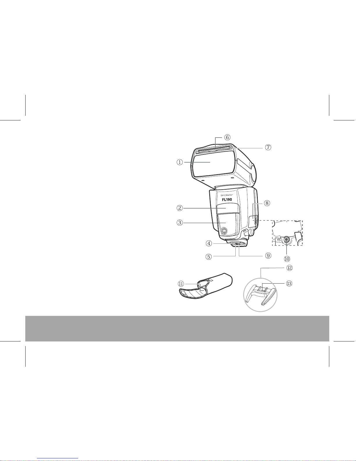
1 Flash head
2 Wireless sensor
3 AF assist lamp
4 Mounting foot
5 Locking pin
6 Catch light reflector panel (retracted)
7 Wide panel (retracted)
8 Contact cover
9 Flash foot contacts
10 PC Terminal
11 Mini flash stand storage pocket
12 Mini flash stand
13 Mini flash stand shoe
PARTS IDENTIFICATION
4
Page 7
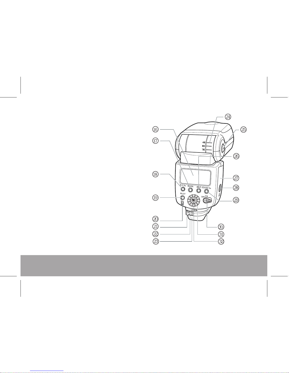
16 LCD panel
17 Flash mode button
18 LCD panel illumination/custom function
settings button
19 Pilot lamp/test firing/wireless
slave power on button
20 Flash exposure confirmation light
21 Mounting foot's lock lever
22 Lock-release button
23 Dust-and water-resistant shield
24 Bounce angle scale
25 Bounce lock release button
26 Rear-curtain sync shortcut button (Canon) |
ISO /Aperture value button /
Group(A B C) button (Nikon)
27 Battery compartment cover
28 Battery compartment lock
29 ZOOM button/wireless selector/
wireless set button
30 Power switch
31 Selection dial
32 Select/set button
5
Page 8
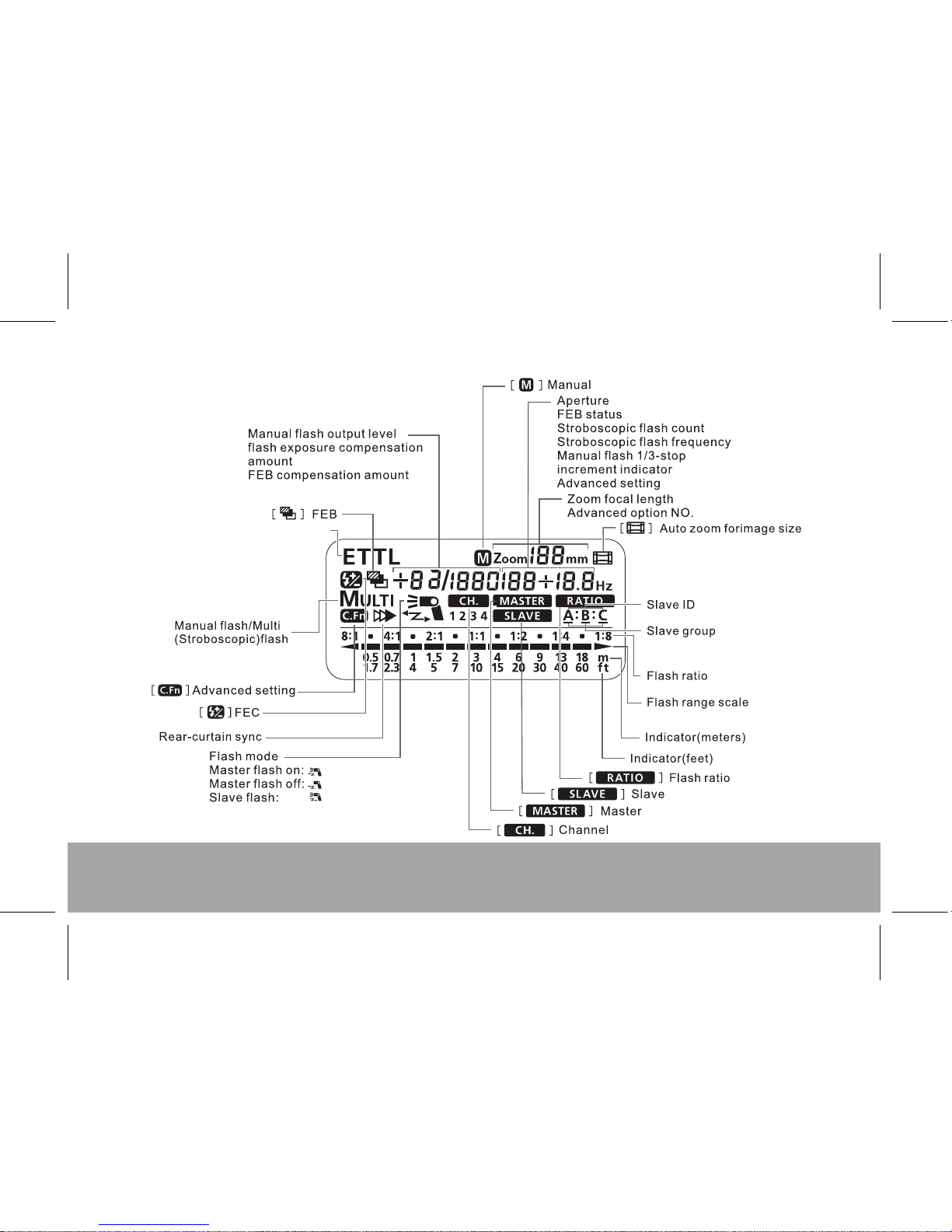
LCD PANEL
6
iTTL/ETTL flash mode
Page 9
OPERATIONS
7
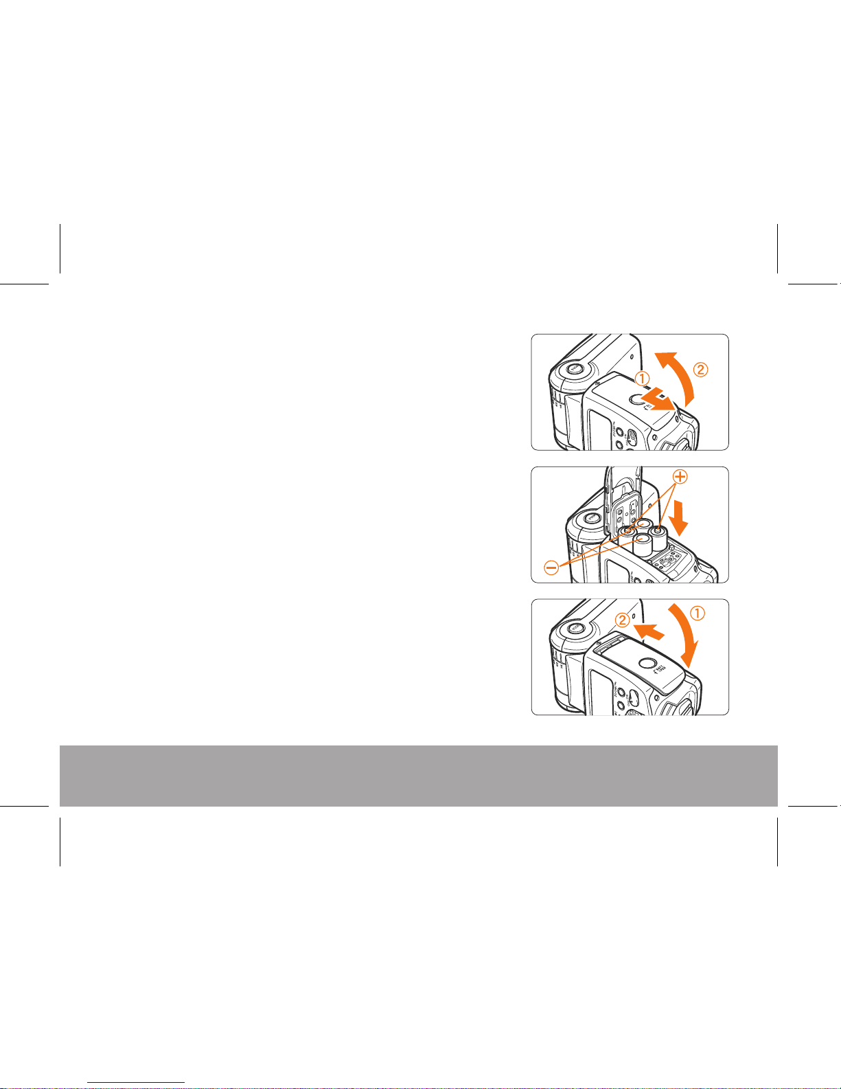
Installing the Batteries
Use your thumb to press the battery compartment
lock lever, then slide it as shown by the arrow ① to
open the cover.
Install the batteries. Make sure the +and -battery
contacts are properly oriented as shown by the
diagram inside the battery compartment.
Close the battery compartment cover and slide it
as shown by the arrow. When the cover clicks in
place, it will be locked.
Be sure to use fresh AA batteries. For best
performance, avoid mixing battery brands or types.
Page 10
8
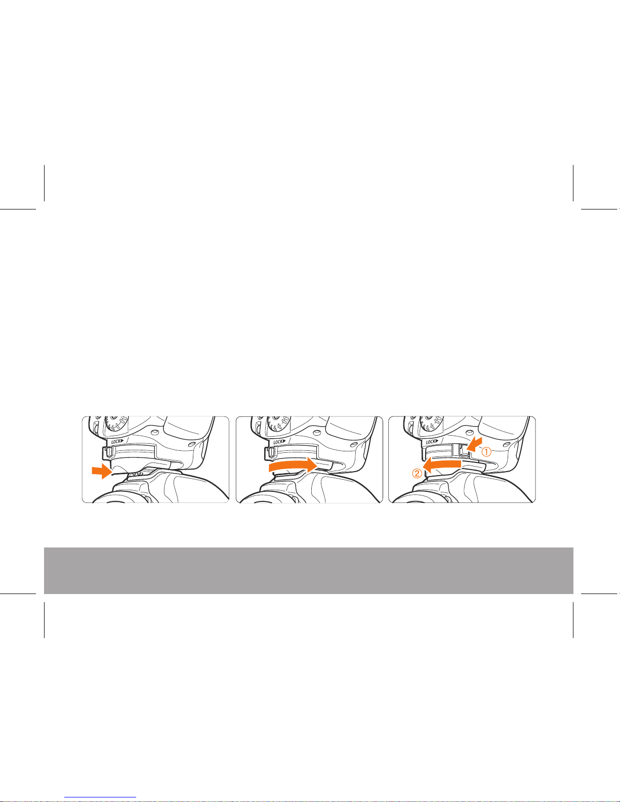
Attaching to the Camera
To attach the flash to your camera, slip the flash’s mounting foot all the way into the
camera’s hot shoe.
Secure the flash by sliding the lock lever on the mounting foot to the right. When the
lock lever clicks into place, it will be locked.
To detach the flash, press the lock-release button, slide the lock lever to the left and
remove the flash from the camera hot shoe.
Page 11
9
Basic Functions
Power-on and Power-off the flash using the OFF/ON power switch (30). When the
PILOT light (19) turns red the flash is charged and ready for use. If the LCD screen
blinks LO, there is not sufficient battery capacity to power your flash. Replace the
batteries with fresh AA batteries.
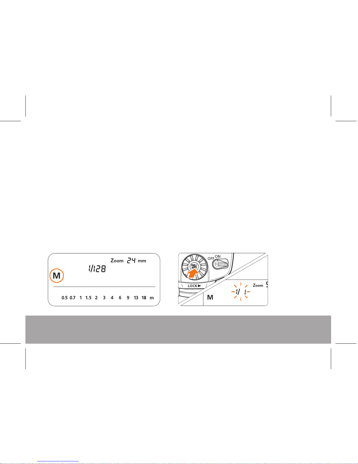
M Mode allows you to set the flash output from 1/128 power to 1/1 full power in 1/3
stop increments. In the M Mode, use a hand-held flash meter to determine the
required flash output to obtain a correct flash exposure. To select the output, press
the MODE button until M is displayed. Press the Select/Set button and rotate the
Selection Dial until the desired output is shown on the LCD. Press the Select/Set
button to set the output level.
Page 12

10
Multi Mode is a stroboscopic flash mode where a rapid series of flashes is fired. It can
be used to capture multiple images of a moving subject in a single photograph. To
achieve this effect your camera’s shutter must remain open. You can set the firing
frequency (number of flashes per second expressed as Hz), the number of flashes, and
the flash output. To set, press the MODE button until Multi is displayed on the LCD.
Press the select button and use the select dial to adjust flash output, the number of
flashes and firing frequency. Once these are set, press the Select/Set button to confirm
the setting. The output may be adjusted to 1/128-1/64-1/32-1/16-1/8-1/4, flash
frequency may be set from 1~100.
Note: The operation of high frequency flash may be impacted by the state of your
batteries not allowing the flash to recycle fast enough. If you experience problems,
reduce the flash frequency or replace your batteries with a fresh set.
Page 13

11
ETTL Mode (Flash for Canon)
In the ETTL mode the FL190 supports Flash Exposure Compensation (FEC), Flash
Exposure Bracketing (FEB), Rear (Second) Curtain Sync, and Flash Exposure Lock.
Refer to your camera’s instruction manual for proper operation of these features.
i-TTL Mode (Flash for Nikon)
In the i-TTL mode the FL190 supports Flash Exposure Compensation (FEC), Flash
Exposure Bracketing (FEB), Rear (Second) Curtain Sync, and Flash Exposure
Compensation (FEV). Refer to your camera’s instruction manual for proper operation of
these features.
Test Flash
In any mode, you can press the PILOT button to fire the flash. When testing the flash,
the flash will flash at the chosen output power setting.
Page 14

12
Setting the ZOOM Coverage
When attached to the camera and the flash
head is in the 90º position, the position of the
flash zoom head will be set automatically to
match the zoom position of your lens.
To set the zoom position manually, press the
ZOOM button. The Zoom indicator on the
LCD will flash. Rotate the Select Dial until the
desired zoom coverage is displayed on the
LCD. Press the Select/Set button to confirm
the setting.
Note: Using the built-in wide angle panel
when the zoom coverage is set to 24mm will
give you flash coverage for 14mm.
Page 15

13
C.Fn – Custom Function for Canon Model
You can customize the features of the FL190 to suit your shooting preferences.
You do this with Custom Functions Setting.
Page 16

14
Soun d co ntrol setting
Clea rl y defined
functi on setting
C.Fn- 15
C.Fn- 14
C.Fn- 16
AF-ass ist beam firing
Auto zoo m for sensor size
Slav e au to power off timer
Slave au to power off cancel
Flash ex posure metering
setting
Enab le d
Disa bl ed
Enab le d
Disa bl ed
60 min ut es
10 min ut es
Within 8 h ours
Within 1 h our
Spee dl ite button and dial
Spee dl ite dial only
2 minu te s(DEFAULT)
5 minu te s
10 min ut es
30 min ut es
1 hour
2 hour s
3 hour s
4 hour s
5 hour s
OFF
ON
NO
Cust om ize the default recov er y setting
Auto power off
(Sleep mode)
C.Fn- 08
C.Fn- 09
C.Fn- 10
C.Fn- 11
C.Fn- 12
C.Fn- 13
N/A
Page 17

15
C.Fn – Custom Function for Nikon Model
You can customize the features of the FL190 to suit your shooting preferences.
You do this with Custom Functions Setting.
Setting No.
Settings & Description
Function
Custom
Function No.
Distance indicator display
Meters(m)
Feet(ft)
Disabled
Enabled
compensation in 1/3 EV
compensation in 1 EV
Enabled
Disabled
C.Fn- 00
C.Fn- 01
C.Fn- 02
C.Fn- 03
C.Fn- 04
C.Fn- 05
C.Fn- 06
C.Fn- 07
Repeat the main flash unit
flash mode
Flash compensation
under auto flash
Enable or disable the
power zoom function
Manually set the zoom position
when the built-in wide panel
damaged
Test the flash output level
under i- TTL mode
Quickflash with continuous
Analog Lighting
Disabled
Disabled
Enabled
1/128
1/32
Full output
Enabled
Enabled camera analog lighting
Enabled flash analog lighting
Enabled flash&camera analog lighting
Disabled all
Page 18

16
Sound control setting
Clearly defined
function setting
C.Fn- 15
C.Fn- 14
C.Fn- 16
Slave auto power off ti me r
Slave auto power off ca ncel
Flash exposure metering
setting
Enabled
Disabled
60 minutes
10 minutes
Within 8 hours
Within 1 hour
Speedlite button and dial
Speedlite dial only
2 minutes
5 minutes
10 minutes
30 minutes
1 hour
2 hours
3 hours
4 hours
5 hours
OFF
ON
NO
Customize the default rec ov er y se tting
Auto power off
(Sleep mode)
C Fn- 08.
C Fn- 09.
C Fn- 10.
C Fn- 11.
C Fn- 12.
C Fn- 13.
AF assist illuminato r / fl as h
function canceled
Enabled AF assist illuminator / flash f un ct io n
Cancel AF assist illuminator,Enabl ed f la sh f unction
Power off auto
A
auto
(D E FA U LT)
Enabled AF assist illuminator ,canc el f la sh f unction
N/A
Page 19

17
To set Custom Functions, press and hold the C, Fn button until the Custom
Function setting menu appears on the LCD. Use the Select Dial until the Fn
number corresponds to the Custom Function you would like to set. Press the
Select/Set button. The setting number will flash. Rotate the Select Dial until the
desired setting number appears. Press the Select/Set button to confirm your
choice.
Sound Prompt
If the Sound Prompt function is enabled, the FL190 will beep with a different
sound pattern indicating its current status. The Sound Prompt factory default is off.
The meaning of the sounds are in the following table:
Page 20

18
Sound Meaning Operation
Beep Twice The flash has been Normal
turned on and is ready
for normal operation.
Beep Three Times The flash is charging. Wait for the charging
to be complete.
Beep Three Times Possible under exposure Adjust the exposure
Twice compensation or change
the shooting conditions.
Beep Beep Beep Possible over exposure Adjust exposure setting or
shooting condition.
Quick Continuous Beeps Low battery power Please replace the batteries.
Long Beep The flash is fully charged Normal
and ready to fire.
Page 21

19
Wireless Flash
In the Master flash mode, the FL190 will transmit an Optical Pulse signal to other slave
flashes with the same system (FL 190 for Canon will control other FL190’s for Canon or
other Canon brand flashes. FL190 for Nikon will control other FL190’s for Nikon or other
Nikon brand flashes).
When set as a slave, the FL190 can receive signals from models of the same brand.
(FL190 or Canon Brand for FL190 for Canon, FL190 or Nikon Brand for FL190 for Nikon.)
Set the Flash to Master Mode
To set the FL190 to the Master Mode, press the ZOOM button for three seconds. The
remote flash icon will appear and OFF flashes on the LCD. Use the select dial to choose
Master, then press the Select/Set button to confirm. To set the channel or power ratio,
press the ZOOM button until the desired option flashes. Rotate the Select Dial to choose
the desired option then press the Select/Set button to confirm the setting.
Set the Flash to Slave Mode
To set the FL190 to the Master Mode, press the ZOOM button for three seconds. The
remote flash icon will appear and OFF flashes on the LCD. Use the select dial to choose
Slave, then press the Select/Set button to confirm. To select the channel or slave group,
press the ZOOM button until the item you wish to adjust flashes. Use the Selection Dial to
adjust the setting, then press the Select/Set button to confirm the setting.
Page 22

20
Wireless flash with two slave groups
1. Set the communication channel on each flash to the same channel: 1, 2, 3 or 4
2. Set the flash in each slave group to A or B
3. Set the communication channel of the master flash to the same channel as the slaves.
To set the flash output of each group, press the ZOOM button until RATIO flashes on
the LCD. Rotate the Select Dial until A:B flashes. Press the Select/Set button to
confirm the setting. Rotate the Select Dial to choose the output of group A vs group B.
You are ready to shoot.
Multi-Flash Wireless Lighting
Configurations
You can create two or three slave
unit groups for multi-directional
shooting. The manual flash output
and stroboscopic functions are set
by the master flash.
Page 23

21
Wireless flash with three slave groups
1. Set the communication channel on each flash to the same channel: 1, 2, 3 or 4
2. Set the flash in each slave group to A, B, or C
3. Set the communication channel of the master flash to the same channel as the slaves.
To set the flash output of each group, press the ZOOM button until RATIO flashes on
the LCD. Rotate the Select Dial until A:B C flashes. Press the Select/Set button to
confirm the setting. Rotate the Select Dial to choose the output of group A vs group B.
The output of group C can be adjusted by pressing the Select/Set button until C
flashes. Then rotate the Select Dial to adjust the output of group C ± 3 stops in 1/3 stop
increments.
Press the PILOT button to test the flash communication between groups.
Important Notes
• If the Master flash is set to RATIO A:B group C will not flash.
• If the Ratio A:B is off, all groups will be controlled as a single group.
• Wireless operation is accomplished by optical pulse. The distance and direction of
slave flashes from the master, as well as the ambient lighting conditions, can impact
the ability of the master flash to properly control the slave flashes.
Page 24

22
Multi-Flash Wireless Lighting Configurations
Page 25

23
S1/S2 Mode
Press the ZOOM button for three seconds. The remote flash icon will appear and OFF
flashes on the LCD. Rotate the Select Dial until S1 or S2 flashes. Choose the desired
mode and press the Select/Set button to confirm the setting.
S1 Mode: When the flash is in S1 mode, it will fire in sync with the first flash from the
master flash. To use this mode correctly, the master flash should be set to manual
and without using any red-eye reduction mode.
S2 Mode: This is the “pre-flash cancel mode”. This mode will ignore the pre-flash
used for focusing and red-eye reduction in the TTL flash mode using the cameras
built in flash. Your particular camera may not support this function.
Page 26

24
FEL Lock (Canon)
To use this function, center your subject in the center of the viewfinder of your camera. Press
the AEL button on the camera (*), the flash will pre-flash and the camera will calculate the
appropriate flash output data. Now compose your photo as desired and shoot the picture.
(The function is only available when it is supported by your camera. For more information
refer to your camera instructions.)
FV Lock (Nikon)
Set the AE-L/AF-L function as FV Lock on the camera before using this function. Center your
subject in the center of the viewfinder of your camera and then press the AE-L key or AF-L
key. The flash will pre-flash and the camera will calculate the appropriate flash output data.
Now compose your photo as desired and shoot the picture. (The function is only available
when it is supported by your camera. For more information refer to your camera instructions.)
Creating a Catchlight
With the built-in catchlight panel, you can create a catchlight in the subject's eyes to add life
to the facial expression.
Page 27

25
Built-In Wide-Angle Diffuser
The built-in wide angle diffuser will extend the coverage angle of your flash as well as
providing a softer more pleasing light.
Pull out the built-in wide angle diffuser & catchlight panel assembly. To use the wide angle
diffuser, fold down to cover the flash lens and push the catchlight reflector back into the
flash housing. To use the catchlight panel, pull out the assembly and push the diffusion panel
back into the flash housing.
Page 28

26
Settings Memory and Factory Reset
When you power off the FL190, it will remember your last used settings. This is helpful
when you are set up for a specific shooting situation and the flash goes into the auto power
off mode or you turn the flash off during idle periods to conserve battery use. Don’t forget
to reset your flash to the normal setting when you are done with your shoot. Alternately,
you can reset the FL190 to the factory default settings by opening the battery compartment
door when the flash is ON. This will interrupt power to the flash and when the battery door
is closed, the flash will be reset to the factory default settings.
Page 29

27
Flash Exposure Compensation
You can use the exposure compensation function of the camera to compensate flash output
to get your desired results. You can also adjust the flash brightness ± 6 in 1/3 increments by
pressing the Select/Set button in the ETTL/iTTL mode and rotating the Select Dial to select
the desired adjustment. Press the Select/Set button to confirm the setting.
Rear Curtain Sync
You can use slow shutter speeds to produce motion effects using the rear-curtain sync
function. (For rear curtain sync settings, refer to your camera instructions.) You can turn on
or turn off the rear curtain sync by pressing the rear curtain sync key on the flash.
Note: When flash is used as slave unit, the rear curtain sync function cannot be set on the
flash.
Flash Exposure Bracketing - FEB
The Flash Exposure Bracketing function is set on your camera. Refer to your camera
instructions with your camera model. When the FEB mode is set, exposure compensation
will be made automatically in sequence, for example “normal-under-over”.
Note: For the FEB mode, set the camera's drive mode to single shooting and be sure the
flash is ready before shooting.
Page 30

28
Auto Zoom for Image Size (Canon)
EOS DIGITAL cameras have one of three image sizes. The lens’ effective focal
length will differ depending on the camera’s image size. The flash automatically
recognizes the EOS DIGITAL camera’s image size and automatically sets the flash
coverage for lens focal lengths from 24mm to 105mm. When the flash is attached to a
compatible camera, < > will appear on the flash’s LCD panel.
Page 31

29
Type: On-Camera Electronic Flash
Guide No.: 190’ / 58m (at 105mm focal length, 100 ISO)
Flash coverage: 24 - 105mm (14mm with wide panel) Auto/Manual Zoom
Exposure control system: iTTL/ETTL, Manual flash, frequency flash
Locking Bounce Swivel
Flash Head: Bounce Position - 0º, 45 º, 60 º, 75 º, 90 º
Swivel - 0 º - 180 º Left and Right
Flash Exposure
Compensation: Manual, FEB: ±6 stops in 1/3-stop increments
Multi flash: 1 - 199 Hz
Rear-curtain Sync: Yes
Flash Exposure
Confirmation: Yes
Recycling time: Approx. 0.1 - 5 sec.
Wireless TTL Flash: Optical pulse
4 Channels, 3 Groups
Custom Flash Modes: 17 user selectable settings
Power Source: Four size-AA alkaline batteries or lithium batteries
Power Save Mode: User selectable duration
Dimensions: 7 ½ x 2 15/16 x 1 15/16” / 190 x 75 x 49 mm
Weight: 13.1 oz. / 370 g
Page 32

30
1/1
1/2.
1/4
1/2.
1/16
1/32
1/64
1/12 8
( )Flash coverage mm
15/4 9.2 28/9 1.9 30/98. 4 36/ 118.1 42/137.8 50/1 64 53/1 73.9 58/1 90.3
10.6 /34.8 19.8/ 65 21.2 /69.6 25.5 /83.7 29 .7/97.4 35 .4/116.1 37.5 /123 41/1 34.5
7 5 24 6. / . 14/45.9 15/4 9.2 18/59.1 21/68 .9 25/8 2 26.5 /86.9 29/9 5.1
5.3/ 17.4 9.9/32. 5 10.6 /34.8
12.7 /41.7 14.8/48.6 17 .7/58.1 18.7/ 61.4
20.5 /67.3
3.8/ 12.5 7/23 7.5/ 24.6 9/29.5 10.5 /34.4 1 2.5/41 13. 3/43.6 14. 5/47.6
2.7/ 8.9 4.9/16. 1
5.3/ 17.4
6.4/ 21
7.4/ 24
.3
8.8/ 28.9
9.4/ 30.8 10.3 /33.8
1.9/ 6.2 3.5/11.5 3.8/ 12.5 4.5/14.8 5. 3/17.4 6.3/ 20.7 6. 6/21.7 7. 3/24
1.3/ 4.3 2.5/8.2 2.7 /8.9 3.2/1 0.5 3.7/ 12.1
4.4/ 14.4 4. 7/15.4 5. 1/16.7
14 24
28
35
50 70 80 105
Flash
output
Flash Index of different focal length range (ISO 100, in meters / feet)
Page 33

31
TROUBLESHOOTING
The flash does not fire.
1. The batteries are installed in the wrong orientation. Install the batteries in the
correct orientation.
2. The flash’s batteries are exhausted: If the flash recycling time takes 30 seconds or
longer, replace the batteries.
3. The flash is not attached securely to the camera. Attach the flash’s mounting foot
securely to the camera.
4. The electrical contacts of the flash and camera are dirty. Clean the contacts.
The slave unit does not fire.
1. The slave's wireless mode is not set to <SLAVE>. Set it to <SLAVE>.
2. The slave unit(s) is not positioned properly. Place the slave unit within the master
unit's transmission range. Point the slave unit’s sensor toward the master unit.
The power turns off by itself.
1. Auto power off (sleep) is in effect. Press the shutter button halfway or press the
test fire button.
Page 34

32
The edges or bottom of the picture looks dark.
1. When you set the flash coverage manually, the setting has a higher number than the
lens focal length, resulting in dark edges. Set the flash coverage that is a lower
number than the lens focal length or set it to auto zoom.
2. If only the bottom of the picture looks dark, you were too close to the subject. If the
subject is closer than 2 m/6.6 ft., tilt the flash head downward by 7° (bounce flash).
The flash exposure is underexposed or overexposed.
1. There was a highly reflective object (glass window, etc.) in the picture. Use FE lock.
2. The subject looks very dark or very bright. Set flash exposure compensation. For a
dark subject, set a decreased flash exposure. And for a bright subject, set an
increased flash exposure.
IMPORTANT INFORMATION
• Do not fire flashes from a short distance directly into the eyes of people or animals.
This can cause damage to the retina and may even lead to blindness.
• Always use batteries of the same type, brand, and age. Always replace all 4
batteries at the same time. Do not combine different types, brands, old, or new
batteries. This could cause the batteries to overheat, leak, or explode.
Page 35

33
• While Ni-MH or Lithium AA batteries may be used in your flash, using AA
batteries other than alkaline type may cause improper battery contact due to the
irregular shape of the battery contacts.
• Install the batteries in proper orientation as indicated in the battery chamber.
Installing the batteries incorrectly could cause the batteries to overheat, leak, or
explode.
• If you change the batteries after a period of sustained continuous firing of the
flash, the batteries may become warm or hot. This is normal, however you should
take care when handling the batteries.
• Always switch off the flash before changing the batteries.
• Do not attempt to open the flash because the electronic circuit contains high
voltage.
• If the flashgun is badly damaged and internal components are exposed, remove
the batteries from the flash. Contact customer service. Never try to repair the
flashgun by yourself.
• This product is not water-resistant. Keep it away from rain, snow, and high
humidity areas.
Page 36

34
• Do not clean the flash with agents containing corrosive or flammable substances.
Also, do not store or use the flash in flammable conditions.
• To avoid overheating and degrading the flash tube, do not fire more than 20
continuous flashes in rapid sequence. After 20 continuous flashes, allow a rest
period of at least 10 minutes. If you fire more than 20 continuous flashes in rapid
sequence and then fire more flashes in short intervals, the internal overheating
prevention function may be activated and the recycling time will increase to about
8 to 20 seconds. If this occurs, allow a rest time of about 15 minutes and the flash
recycling time will return to normal..
• If you use a commercially available sync cord to connect the camera to the flash
PC terminal, be sure to set the flash zoom manually for proper coverage.
• In the Multi Mode (stroboscopic flash), the camera’s shutter should remain open
until the flash completes the number of flashes that have been set. The shutter
speed to set on the camera is calculated by Number of flashes ÷ Firing frequency
= Shutter speed. For example, if the number of flashes is 10 and the firing
frequency is 5 Hz, the shutter speed should be at least 2 seconds.
Page 37

35
KEEP IN TOUCH
For more information, tutorials, industry news and tips & tricks, make sure to visit us
at promaster.com, follow our feeds on Twitter @promasterphoto, and subscribe to our
YouTube Channel username ProMasterChannel.
ONE YEAR UNCONDITIONAL GUARANTEE
If for any reason, this ProMaster product fails within ONE YEAR of the date of
purchase, return this product to your ProMaster dealer and it will be exchanged for
you at no charge.
ProMaster products are guaranteed for ONE FULL YEAR against defects in
workmanship and materials. If at any time after one year, your ProMaster product fails
under normal use, we invite you to return it to ProMaster for evaluation.
Made in China
Page 38

Page 39

Page 40

 Loading...