

Promaster D200R, D400R Owner's Manual
Multi-function Studio Flash
OWNER’S MANUAL
Safety Precautions:
1. Before using the flash, make sure that the electrical power supply matches the power requirements indicated on your lighting
equipment. Do not use any power other than the AC specification indicated on your equipment.
2. Do not expose your lighting equipment to sunshine, moisture, dust, dirt, rain, or water.
3. Any exposure to chemical solutions, gasoline, grease, oil, paint, or detergents can result in permanent damage to your
equipment.
4. Do not insert metal parts into any lighting equipment.
5. Dry your hands before handling the equipment. Touching your equipment with wet hands is dangerous to both the equipment and
to you.
6. To unplug your equipment, grasp only the plug. Do not unplug by pulling the electrical wire.
7. If your flash beeps continuously or does not function, turn your flash off and unplug for 30 seconds to reset.
8. Do not attempt to repair your lighting equipment. If a problem arises, contact the store from which you purchased the light.
Specifications:
Model D200R – Code 7893 D400R – Code 7900
Power source AC100-130V / 60Hz
Strobe output 200WS 400WS
Guide No. (ISO100) 45m 65m
Cooling fan Built-in mini fan cooler
Power Range 1/32~1/1(5 steps) Continuously
Recycle time 0.5-1s
Flash duration 1/800-1/10000s
Beam angle 55 °
Slave sensitivity 10 m
Modeling lamp 150W / E27
Color temperature 5600K
Synch cord voltage 6V DC
Triggering
Synch cord/Test flash switch/Slave sensor/Integrated RF trigger
Fuse 10A
Housing size(mm) 136×127×320mm
Weight 2.2kg 2.5kg
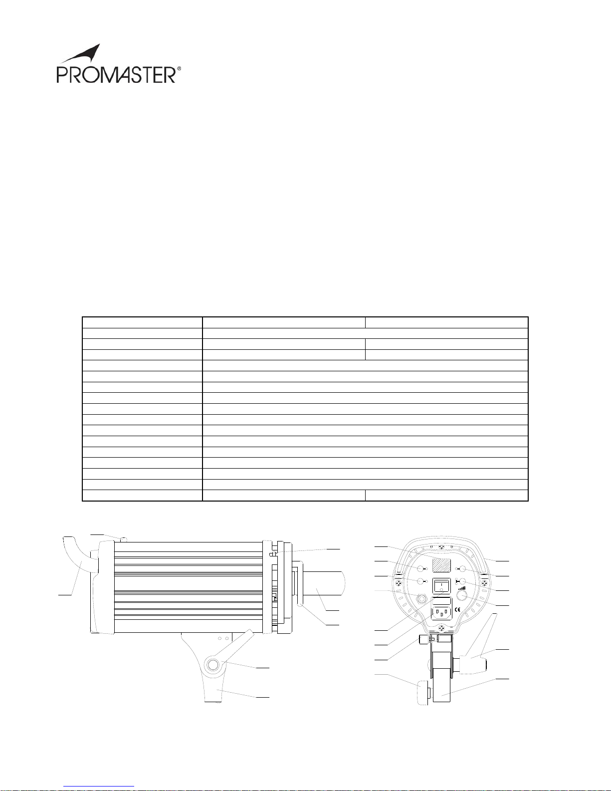
Light Body &Rear Control Panel
-1-
16
15
14
13
14
13
9
2
4
5
6
11
12
3
10
9
Test
RF
Cell
Ready
Free/Prop
Buzz
Model
SYNC
POWER OFF
MODE
ON
1
8
7
17
18

-2-
1. Power Socket 9. Accessory Lock Lever
2. Power Switch 10. Test button
3. Synch Socket 11. Slave/RF Button
4. Modeling Lamp/Charge Indicator 12. Multi-function Knob
5. Buzz Switch 13. Angle Adjustment Handle
6. Digital Screen 14. Stand mount
7. Handle Grip 15. Stand mounting bolt
8. Slave sensor 16. Umbrella holder
Directions for use:
Powering on the Flash and Setting the RF Channel
Insert the power cord into Power Socket (1), the Digital Screen (6) will display ”C0” when the light is turned on by pressing the Power
Switch (2). Choose the RF trigger channel from C0-C7. After 1 or 2 seconds, the Charged Indicator (4) will turn green and the flash is
charged and ready to flash.
Testing the Flash Operation
Press the Test Button (10) to check the flash operation.
Selecting the Trigger Method
Optical Slave:This flash has a built-in Optical Slave Sensor (8). Press the Slave/RF button (11), the indicator lamp next to CELL will
turn green. When another flash fires, this flash will be triggered. Press Slave/RF button (11) again, and the CELL lamp will turn red or
orange. This is the RED-EYE mode. In this mode the flash will ignore the RED-EYE pre-flash from an on camera flash.
RF Trigger:This flash has a built-in RF receiver. Press the SLAVE/RF button (11) until the indicator lamp next to RF lights. The flash is
now in the RF trigger mode and can be triggered using the OPTIONAL matching RF transmitter attached to your camera.
Synch Cord: To trigger your flash with a sync cord, insert one side of synch cord into synch cord socket, connect the other end to the
sync terminal on your camera. While using a sync cord is the most reliable means of triggering your flash, it is also the most
cumbersome.
Audible Ready Signal
To turn on the audible signals, press the Buzz switch (5). When the flash is charged it will beep one time and the indicator will light to
tell you the flash is charged and ready to fire.
Modeling Lamp
The modeling lamp has several modes. Press the Modeling Lamp switch (4), when Free/Prop indicator light is off, the modeling lamp
is off. When the Free/Prop indicator light turns green, the power of the modeling lamp and flash tube are synchronized and can be
adjusted. By pressing the Multi-function Knob (12), the Free/Prop indicator light will turn red and the digital display screen (6) will
twinkle. The output of the modeling lamp & flash output are now set for independent adjustment.
Adjust Output Power of Flash
To adjust the output of the flash, rotate the Multi-function knob (12). The power can be set from 1/32 to 1/1.
Stroboscopic Effect
Turn the flash on and press the Multi-function knob (12) twice. The flash will enter into stroboscopic function. The number of flashes
(2~20 times) can be set by rotating the Multi-function knob (12). Press the Multi-function knob (12) again and you can select the flash
interval (A0-A9).
FP-High Speed Strobe
Turn the flash on and press the Multi-function knob (12) four times, the flash will enter into FP function.
Adjust the RF Receiver Channel
Turn the flash on and press the Multi-function knob (12) five times. The digital display screen (6) shows the current RF receiver
channel. Change the channel by rotating Multi-function knob (12). Please refer to Channel Control Chart for the proper transmitter
settings. Use of this mode requires the OPTIONAL DR Slave Trigger.
Attaching the Reflector
The reflector has 3 pins around the perimeter of its base. Line these pins up with the corresponding notches in the flash head front
collar. Rotate the reflector clockwise until it locks into position. To remove the reflector, push the Accessory Lock Lever (9) on the top
of the flash and rotate the reflector counter clock wise, then pull it away from the flash head.
 Loading...