

Promac VBS-1610 Operating Instructions And Parts Manual

2019.01
Operating Instructions and Parts Manual
16-inch Metalworking Band Saw
Model : VBS-1610
Schweiz / Suisse France
JPW (TOOL) AG TOOL FRANCE SARL
Tämperlistrasse 5 9 Rue des Pyrénées, 91090 LISSES, France
CH-8117 Fällanden Switzerland www.promac.fr
www.promac.ch

2
CE-Conformity Declaration
CE-Konformitätserklärung
Déclaration de Conformité CE
Product / Produkt / Produit:
Metal band saw
Metallbandsäge
Scie à ruban
VBS-1610
Brand / Marke / Marque:
PROMAC
Manufacturer / Hersteller / Fabricant:
TOOL FRANCE SARL
9 Rue des Pyrénées, 91090 LISSES, France
We hereby declare that this product complies with the regulations
Wir erklären hiermit, dass dieses Produkt der folgenden Richtlinie entspricht
Par la présente, nous déclarons que ce produit correspond aux directives suivantes
2006/42/EC
Machinery Directive
Maschinenrichtlinie
Directive Machines
2014/30/EU
electromagnetic compatibility
elektromagnetische Verträglichkeit
compatibilité électromagnétique
designed in consideration of the standards
und entsprechend folgender zusätzlicher Normen entwickelt wurde
et été développé dans le respect des normes complémentaires suivantes
EN ISO 12100:2010
EN ISO 16093:2017
EN 60204-1:2006+A1:2009
EN 61000-6-2:2005
EN 61000-6-4:2007+A1:2011
Responsible for the Documentation / Dokumentations-Verantwortung / Résponsabilité de Documentation:
Head Product-Mgmt. / Leiter Produkt-Mgmt. / Resp. Gestion des Produits
TOOL FRANCE SARL
2018-12-20 Christophe SAINT SULPICE, General Manager
TOOL FRANCE SARL
9 Rue des Pyrénées, 91090 LISSES, France

3
1.0 Table of contents
Section Page
1.0 Table of contents ............................................................................................................................................ 3
2.0 Safety warnings .............................................................................................................................................. 4
3.0 Specifications ................................................................................................................................................. 6
4.0
Uncrating and assembly
5.0 Installation ...................................................................................................................................................... 7
6.0 Electrical connections .................................................................................................................................... 7
6.1 Three-phase test run .................................................................................................................................. 7
7.0 Controls .......................................................................................................................................................... 8
8.0 Adjustments ................................................................................................................................................... 9
8.1 Blade tensioning ......................................................................................................................................... 9
8.2 Blade tracking ............................................................................................................................................. 9
8.3 Blade guide adjustment .............................................................................................................................. 9
8.4 Top guide adjustment ............................................................................................................................... 10
8.5 Changing saw blades ............................................................................................................................... 10
8.6 Work lamp ................................................................................................................................................ 10
9.0 Blade selection ............................................................................................................................................. 10
9.1 Material composition ................................................................................................................................ 10
9.2 Tooth shape ............................................................................................................................................. 10
9.3 Set type .................................................................................................................................................... 10
9.4 Gage ......................................................................................................................................................... 11
9.5 Kerf ........................................................................................................................................................... 11
9.6 Width ........................................................................................................................................................ 11
9.7 Blade breakage ........................................................................................................................................ 11
10.0 Welder operation ........................................................................................................................................ 11
10.1 Shearing ................................................................................................................................................. 11
10.2 Removing Teeth ..................................................................................................................................... 12
10.3 Welding .................................................................................................................................................. 12
10.4 Annealing ............................................................................................................................................... 13
10.5 Blade grinding ........................................................................................................................................ 14
10.6 Secondary Annealing ............................................................................................................................. 14
10.7 Welder Clean-Up .................................................................................................................................... 14
11.0 Band saw operation ................................................................................................................................... 14
11.1 Blade break-in procedure ....................................................................................................................... 14
11.2 Setting blade speed ................................................................................................................................ 14
11.3 Evaluating cutting efficiency ................................................................................................................... 15
12.0 User-maintenance ...................................................................................................................................... 15
12.1 Lubrication schedule .............................................................................................................................. 15
12.2 Gearbox oil ............................................................................................................................................. 15
13.0 Troubleshooting ......................................................................................................................................... 16
13.1 Operating problems ................................................................................................................................ 16
13.2 Mechanical and electrical problems ....................................................................................................... 17
13.3 Welded blade inspection ........................................................................................................................ 18
13.4 Welder mechanical problems ................................................................................................................. 19
14.0 Speed and pitch chart ................................................................................................................................ 20
15.0 Typical Band Saw Operations .................................................................................................................... 21
16.0 Replacement Parts ..................................................................................................................................... 22
16.1.1 VBS-1610 Band Saw – Exploded View ............................................................................................... 22
16.1.2 VBS-1610 Band Saw – Parts List ........................................................................................................ 23
Gear Box Compound Assembly ...................................................................................................................... 23
16.1.3 VBS-1610 Band Saw (Welder Assembly) – Exploded View ............................................................... 27
17.0 Electrical diagram (VBS-1610) ................................................................................................................... 30
................................................................................................................................. 7
2.0 Safety warnings
Do not wear gloves while operating this machine.
In addition to the safety requirements contained in
these operating instructions and your country’s
applicable regulations, you should observe the
generally recognized technical rules concerning the
operation of woodworking machines.
Any other use exceeds authorization.
In the event of unauthorized use of the machine, the
manufacturer renounces all liability and the
responsibility is transferred exclusively to the
operator.
3.2 General safety notes
Woodworking machines can be dangerous if not used
properly. Therefore the appropriate general technical
rules as well as the following notes must be observed.
Read and understand the entire instruction manual
before attempting assembly or operation.
Install the machine so that there is sufficient space for
safe operation and workpiece handling.
Keep work area well lighted.
The machine is designed to operate in closed rooms
and must be bolted stable on firm and levelled table
surface or on the supplied cabinet stand.
Make sure that the power cord does not impede work
and cause people to trip.
Keep the floor around the machine clean and free of
scrap material, oil and grease.
Stay alert!
Give your work undivided attention.
Use common sense. Do not operate the machine
when you are tired.
Keep an ergonomic body position.
Maintain a balanced stance at all times.
Do not operate the machine under the influence of
drugs, alcohol or any medication. Be aware that
medication can change your behaviour.
Keep this operating instruction close by the machine,
protected from dirt and humidity, and pass it over to
the new owner if you part with the tool.
No changes to the machine may be made.
Daily inspect the function and existence of the safety
appliances before you start the machine.
Do not attempt operation in this case, protect the
machine by unplugging the power cord.
Before operating the machine, remove tie, rings,
watches, other jewellery, and roll up sleeves above
the elbows.
Remove all loose clothing and confine long hair.
Wear safety shoes; never wear leisure shoes or
sandals.
Always wear the approved working outfit:
- safety goggles
- ear protection
- dust protection
Never reach into the machine while it is operating or
running down.
Keep children and visitors a safe distance from the
work area.
Never leave a running machine unattended. Before
you leave the workplace switch off the machine.
Do not operate the electric tool near inflammable
liquids or gases.
Observe the fire fighting and fire alert options, for
example the fire extinguisher operation and place.
Do not use the machine in a dump environment and
do not expose it to rain.
Before machining, remove any nails and other foreign
bodies from the workpiece.
Work only with well sharpened tools.
Machine only stock which rests securely on the table.
Always close the chuck cover before you start the
machine.
4

Specifications regarding the maximum or minimum
size of the workpiece must be observed.
Do not remove chips and workpiece parts until the
machine is at a standstill.
Do not stand on the machine.
Connection and repair work on the electrical
installation may be carried out by a qualified
electrician only.
Have a damaged or worn power cord replaced
immediately.
Make all machine adjustments or maintenance with
the machine unplugged from the power source.
Environmental protection
Protect the environment.
Your appliance contains valuable materials which can
be recovered or recycled. Please leave it at a
specialized institution.
This symbol indicates separate collection for electrical
and electronic equipment required under the WEEE
Directive (Directive 2012/19/EC) and is effective only
within the European Union.
5

6
3.0 Specifications
Model number ......................................................................................................................................... VBS-1610
Stock number ............................................................................................................................................ 414485T
Blade speed ............................................................................................................................................... variable
Low range ....................................................................................................................................... 20-80 MPM
High range ................................................................................................................................. 250-1000 MPM
Capacities:
Height (max. thickness) ......................................................................................................................... 250 mm
Throat (max. width) ............................................................................................................................... 393 mm
Welder capacity .................................................................................................................................... 3-16 mm
Motor ................................................................................................ TEFC, 2HP (1.5kW), 3PH, 400V ,3.3A, 50Hz
Table size ......................................................................................................................................... 550 x 600 mm
Table height from floor at 90° ................................................................................................................... 1000 mm
Table tilt:
Front and Back ......................................................................................................................................... 8 deg.
Right ....................................................................................................................................................... 15 deg.
Left ......................................................................................................................................................... 12 deg.
Welder (KVA) ............................................................................................................................................. 2.4
Blade length (approximate) ....................................................................................................................... 3136mm
Blade width, maximum .................................................................................................................................. 16mm
Overall height ............................................................................................................................................ 1840mm
Floor space required ........................................................................................................................... 940x711mm
Gearbox oil capacity .................................................................................................................. 2500 cc (0.66 gal.)
Weights:
Net ............................................................................................................................................ 900 lbs. (408 kg)
Shipping ................................................................................................................................. 1122 lbs. (510 kg)
The specifications in this manual were current at time of publication, but because of our policy of continuous
improvement, Promac reserves the right to change specifications at any time and without prior notice, without incurring
obligations.
7
4.0
Uncrating and assembly
6.0 Electrical connections
1. Finish uncrating the band saw. Contact your
distributor if any damage has occurred during
shipping.
2. Remove any preservative with kerosene or
diesel oil. Do not use gasoline, paint thinner, or
any cellulose-based product, as these will
damage painted surfaces.
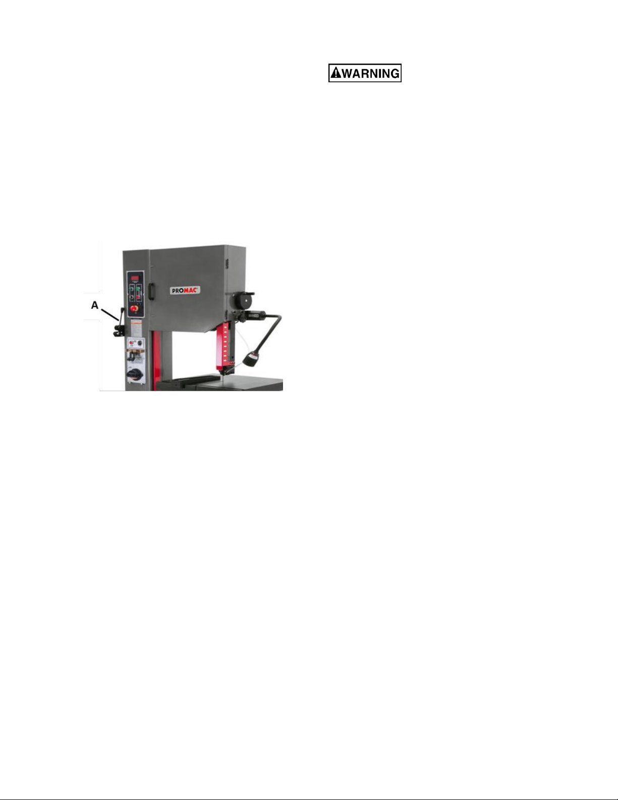
3. Remove two socket head cap screws from left
side of vertical column. Attach shear assembly
(A, Figure 1) to column by inserting hex cap
screws.
4. Place rip fence onto table and tighten with
locking knob.
Figure 1
All electrical connections must
be done by a qualified electrician. All
adjustments or repairs must be done with
machine disconnected from power source.
Failure to comply may cause serious injury.
The VBS-1610 Band Saw is rated at 400V and
without plug.
You may connect a proper plug suitable for 400 volt
operation, or "hard-wire" the machine directly to
your electrical panel provided there is a disconnect
near the machine for the operator.
The band saw must be grounded. A qualified
electrician can make the proper electrical
connections and confirm the power on site is
compatible with the saw.
Before connecting to power source, make sure
switch is in off position.
6.1 Three-phase test run
After wiring the band saw, you should check that the
wires have been connected properly. Connect
machine to power source and turn it on for an instant
to watch direction of blade movement.
If blade runs upward instead of downward,
disconnect machine from power, and switch any
two of the three leads in the motor junction box (see
section 18.0, Electrical diagram).
5.0 Installation
1. Remove three (3) nuts and washers holding
band saw to shipping crate bottom.
2. Use the lifting ring to lift band saw into its
permanent location. For best performance,
band saw should be bolted to floor after a level
position has been found.
3. Using a square, adjust table 90 degrees to
blade, both front to back and side to side.
Loosen the hex cap screws below the table to
move it and tighten to hold table in place. If
necessary, adjust the pointers to zero should
they read different once table is perpendicular
to blade in both directions.
4. To level the machine, place a machinist's level
on the table and observe in both directions.
5. Use metal shims under the appropriate hold
down screw. Tighten screw and recheck for
level.
6. Adjust with additional shims, as required, until
table is level when all mounting screws (or nuts)
are tight.
8
7.0 Controls
I
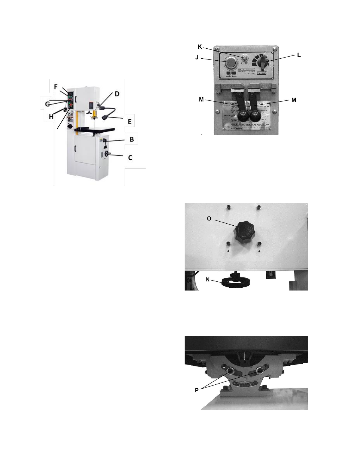
Low/High Range Shift Lever (B, Figure 2) – Pull
toward front of machine to shift into low speed range.
Push toward rear of machine to shift into high speed
range. CAUTION: Do not change speed range
while machine is running. Adjust only when
machine is stopped.
Figure 2
Variable Speed Handwheel (C, Figure 2) – Turn
clockwise to increase speed and counterclockwise
to decrease speed. CAUTION: Do not turn
handwheel while machine is stopped. Adjust
speed only when machine is running.
Upper Blade Guide Lock Knob (D, Figure 2) –Turn
counterclockwise to loosen and clockwise to tighten.
Work Lamp Switch (E, Figure 2) – on top of lamp
shade; turns lamp on and off.
Main Motor / Sand Wheel Start Switch (F, Figure
2) – Press to start band saw.
Main Motor / Sand Wheel Stop Switch (G, Figure
2) – Press to stop band saw.
Shear Lever (H, Figure 2) – UP position allows
insertion of blade end into shear. Pull lever DOWN
to cut blade.
Emergency Stop Switch (I, Figure 2) – Press to
stop all machine functions. Turn 90° to reset.
Weld Button (J, Figure 3) – located on blade welder
panel. Press and hold to start welding. Shuts off
automatically when weld is done. Release when
weld is completed.
Anneal Button (K, Figure 3) – located on blade
welder panel. Press and hold to anneal blade,
release to stop.
Blade Clamp Pressure Knob (L, Figure 3) –
located on blade welder panel. Sets pressure for
different width blades. Turn counterclockwise to
bring blade clamps closer together, clockwise to
separate.
Blade Clamps (M, Figure 3) – located on blade
welder panel. DOWN position allows insertion of
blade into clamp. UP position locks blade.
Figure 3
Blade Tension Handwheel (N, Figure 4) – located
on underside of upper frame. Turn clockwise to
tension blade; counterclockwise to release tension
on blade.
Blade Tracking Handle (O, Figure 4) – located at
upper rear of saw. Turn clockwise to track blade
toward front of blade wheel. Turn counterclockwise
to track blade toward rear of blade wheel.
Figure 4
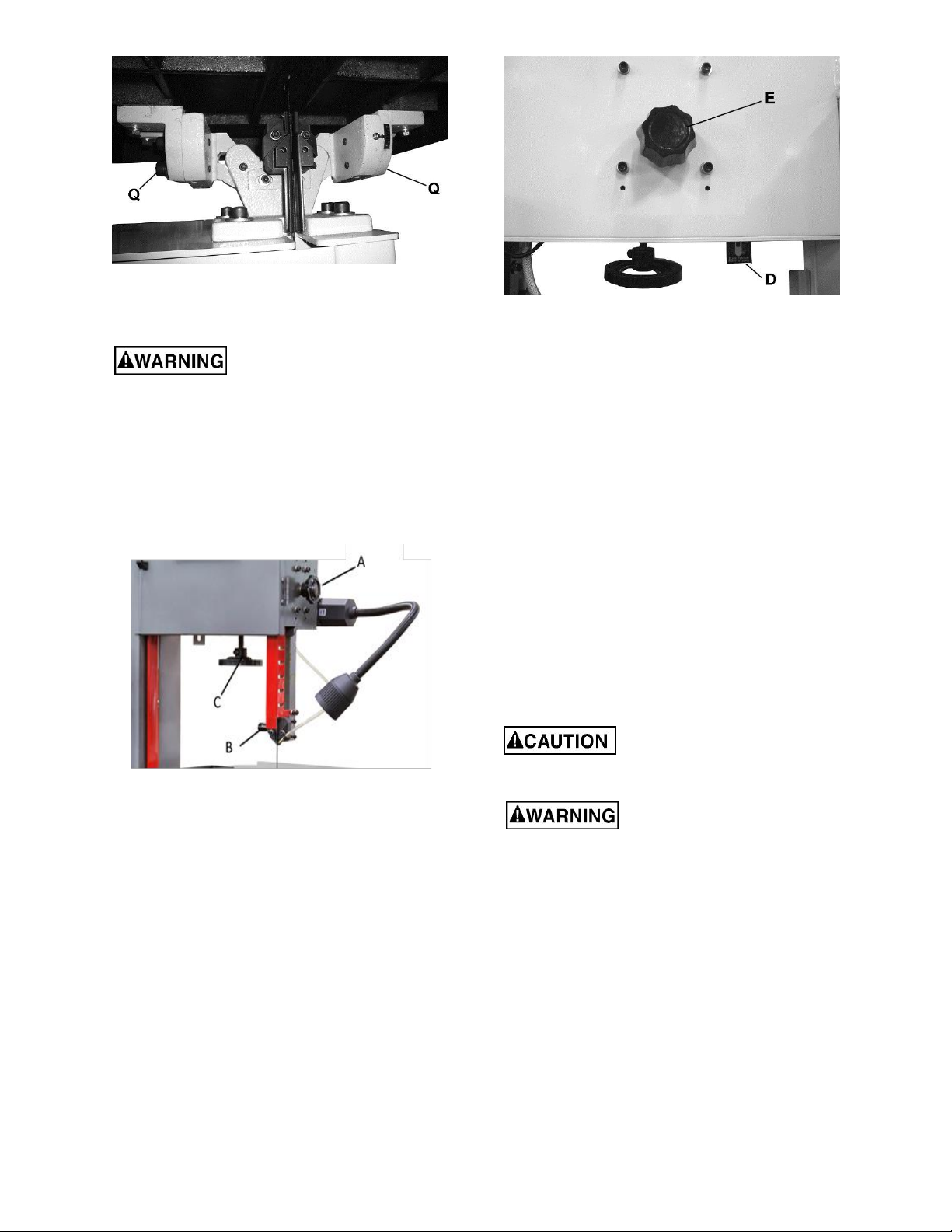
Table Tilt Mechanism – located under work table.
To tilt table left or right, loosen two socket head cap
screws (P, Figure 5) at rear of mechanism. To level
table front to back, loosen four socket head cap
screws (Q, Figure 6) on either side of mechanism.
Figure 5
9
Figure 6
8.0 Adjustments
All adjustments or repairs to
machine must be done with power off and
machine disconnected from power source.
Failure to comply may cause serious injury.
8.1 Blade tensioning
1. Raise upper blade guide by loosening lock knob
(A, Figure 7) and lifting blade guide handle (B,
Figure 7) to its highest position.
Figure 8
8.2 Blade tracking
Blade tracking may be required periodically
depending upon blade size and tension. The blade
must be tensioned as outlined in section 9.1 Blade
tensioning. Disconnect machine from power source
and open upper blade wheel door. Shift high-low
gear box lever into neutral position. Turn upper
blade wheel by hand while observing blade position
on upper blade wheel. If adjustment is necessary:
1. Turn blade tracking knob (E, Figure 8)
clockwise to track blade toward front of blade
wheel.
2. Turn tracking knob counterclockwise to track
blade toward rear of blade wheel. Blade should
run next to, but not against, the wheel flange.
Note: Upper and lower blade guides should be
moved away and left loose from the blade while
tracking adjustments are being made.
8.3 Blade guide adjustment
Figure 7
2. Apply finger pressure to blade. Travel from
vertical should be approximately 10mm each
way.
3. To tighten blade, turn handwheel (C, Figure 7)
clockwise. To loosen blade, turn handwheel
counterclockwise.
4. Use blade tension indicator (D, Figure 8) as
reference only. Blade should be tensioned
using the finger pressure method.
Blade guides must be properly
adjusted or damage may occur to blade and/or
guides.
Guard has been removed to
show detail. Always operate saw with guard in
place and properly adjusted. Failure to comply
may cause serious injury.
Blade guide adjustment has been set by the
manufacturer. Should future adjustment be needed,
proceed as follows.
1. Loosen upper blade guide lock knob and raise
guide assembly to half-way between table and
head, then tighten lock knob
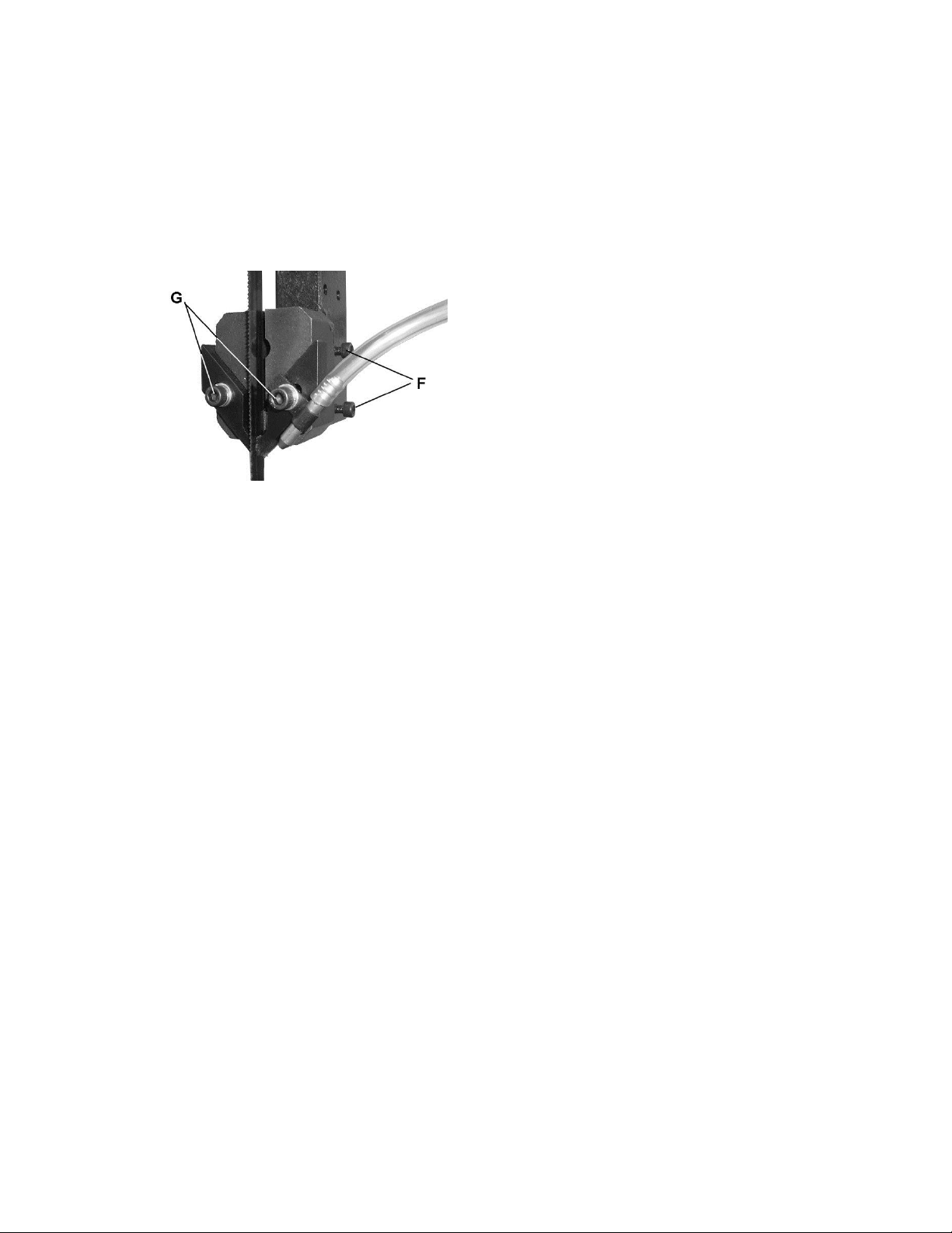
2. Loosen two set screws (F, Figure 9) and adjust
guide so that blade guides are in back of saw
teeth. Blade guides must be adjusted far
enough back to clear saw blade even during
cutting operation when the blade is deflected
toward the rear.
3. Tighten the two screws (F, Figure 9).
10
4. Open upper access door and rotate blade
wheel by hand until weld portion of blade is
between the two fingers.
5. Loosen two socket head cap screws (G, Figure
9) and adjust each finger toward the blade.
They should not touch the blade. Adjust for
0.25mm clearance on either side.
6. Retighten the two screws (G, Figure 9) once
proper adjustment has been made. Be sure that
adjustment for air nozzle has not changed and
it directs the flow of air to the cut.
Figure 9
7. Adjust lower blade guides in similar manner.
Note: Even properly adjusted blade guides will show
wear after continual use. Readjust as necessary. If
the blade guides become difficult to adjust, switch
the left and right blade guides.
8.4 Top guide adjustment
Always position top guide to within 3mm of the top
surface of workpiece. This minimizes exposure of
operator’s hands to the saw blade.
8.5 Changing saw blades
7. Tension blade by turning tension handwheel.
Rotate wheel by hand and make sure blade is
properly seated in blade guides. Blade guides
will have to be adjusted if the replacement blade
is a different type and width.
8. Turn on saw and check blade tracking. Adjust
tracking if necessary.
8.6 Work lamp
The work lamp uses a standard 20W/24V Halogen
light.
9.0 Blade selection
Proper blade selection is just as important to band
saw operation as is blade speed and material feed.
Proper blade selection will impact blade life,
straightness of cut, cut finish, and efficiency of
operation. Excessive blade breakage, stripping of
teeth, and waviness of cut are some of the results of
improper blade selection.
Blades are classified by material composition, tooth
shape, tooth pitch, tooth set, gage of the band
material, and kerf of the set (width of cut).
9.1 Material composition
Carbon Steel – low cost, for use with non-ferrous
materials, wood, and plastics.
High Speed Steel – resists heat generated by dry
cutting. Used for ferrous metals.
Alloy Steel – tough and wear resistant, cuts faster
with longer blade life. Used on hard materials. More
expensive than carbon or high speed steel.
Carbide Tipped – for cutting unusual materials
such as uranium, titanium, or beryllium.
1. Disconnect saw from power source.
2. Move upper blade guide to its highest position
and lock in place.
3. Open both wheel doors. Turn tension
adjustment handwheel counterclockwise to
loosen tension on blade.
4. Remove blade from both wheels and maneuver
it around blade guard on column and protective
shield on upper blade guide. Use gloves when
handling blades.
5. Install new blade by maneuvering around blade
guard on column and protective shield on upper
blade guide.
6. Place it between the fingers of both blade
guides and onto both wheels. Position next to
both wheel flanges. Make sure teeth point down
toward table. NOTE: If teeth will not point
downward regardless of blade orientation, the
blade is inside-out. Twist blade outside-in and
reinstall.
9.2 Tooth shape
Note: When cutting thin materials, the rule for blade
pitch is to have a minimum of two teeth engaging
the material being cut at all times.
Standard Tooth - generally used to cut ferrous
metals, hard bronze, hard brass, and thin metals.
Skip Tooth - have better chip clearance (larger
gullet) and are used on softer, non-ferrous materials
such as aluminum, copper, magnesium, and soft
brass.
Hook Tooth - provides a chip breaker and has less
tendency to gum up in softer materials. Used in the
same materials as skip tooth but can be fed faster
than standard or skip tooth blades.
9.3 Set type
Straight Set – used for free cutting non-ferrous
materials; i.e., aluminum, magnesium, plastics, and
wood.
11
Wavy Set – used on materials of varying thickness
(pipe, tubing, and structural shapes).
Raker Set – used in large cuts on thick plate and
bar stock where finish of cut is not as important as
speed.
9.4 Gage
Gage is the thickness of material from which the
blade is produced. The thicker the material, the
stronger the blade.
9.5 Kerf
Kerf is the width of a cut. Kerf will vary according to
the set of the blade teeth.
10.0 Welder operation
Wear eye protection while
operating welder. Use care when handling blade
after welding to avoid burns.
The welding procedure involves the following steps:
Shearing the blade, grinding teeth to allow for the
weld area, the actual welding, inspection of blade,
annealing, grinding and a final inspection of blade.
This procedure can be accomplished using the
shear and welder assemblies on your band saw.
Proceed as follows:
10.1 Shearing
9.6 Width
The thinner the blade, the tighter will be the
minimum radius of cut. Always use widest blade
possible for the job.
General rules for blade selection:
Select coarser pitch blades for thicker or softer
material.
Select finer pitch blades for thinner or harder
material.
Use fine pitch blades to obtain a smooth finish.
Use coarse pitch blades to obtain faster cutting
speeds (thick material).
To prevent premature blade wear, use fastest
practical speed.
Adjust feed rate to ensure continuous cutting
action.
Run the bandsaw with blade centered in upper
and lower guides, and guide fingers adjusted as
close as possible without touching the blade or
weld joint.
Never adjust guide fingers
while blade is running. Failure to comply may
cause serious injury.
9.7 Blade breakage
Band saw blades are subject to high stresses and
breakage may sometimes be unavoidable. However,
many factors can be controlled to help prevent most
blade breakage. Here are some common causes for
breakage:
1. Misalignment of blade guides.
2. Feeding workpiece too quickly.
3. Using a wide blade to cut a short radius curve.
4. Excessive tension.
5. Teeth are dull or improperly set.
6. Upper guides are set too high off the workpiece.
7. Faulty weld on blade.
Cut blade to longest length needed for band saw.
Using the shear to cut your blade will ensure that cut
ends are flat, square and smooth.
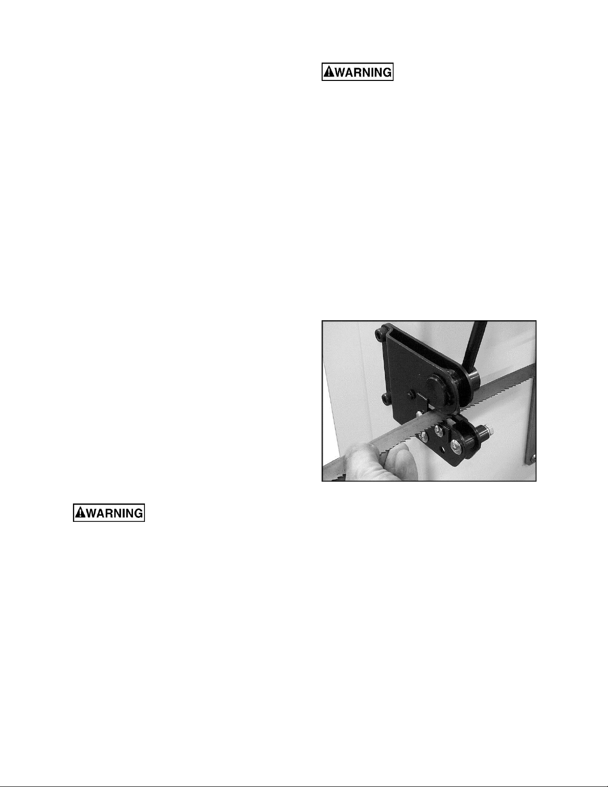
1. Place handle in upright position.
2. Position blade against back of square cutting
guide of shear. See Figure 10. Make sure blade
is held square with shear knife, so that cut will
be square with blade.
Figure 10
3. Position blade so that cut is made at a place that
allows for uniform spacing of teeth. See Figure
11.
4. Bring handle down firmly to cut blade.
IMPORTANT: If a blade has been cut by using snips,
the ends of the blade must be ground square before
welding them together, as shown in Figure 12.
 Loading...