

Promac SY-350-ALU Operating Instructions And Parts Manual
1
Operating Instructions and Parts Manual
Miter Circle Saw 2016.03
Model SY-350-ALU
Schweiz / Suisse France
JPW (TOOL) AG. TOOL France / PROMAC
Tämperlistrasse 5 57, rue du Bois Chaland, Z.I. du Bois Chaland
CH-8117 Fällanden Switzerland case postale 2935 FR-91029 Evry Cedex
www.promac.ch www.promac.fr

2
CE-Conformity Declaration
Product: Miter Circle Saw
SY-350-ALU
Brand: PROMAC
Manufacturer:
JPW (Tool) AG, Tämperlistrasse 5, CH-8117 Fällanden, Switzerland
On our own responsibility we hereby declare that this product complies
with the regulations
* 2006/42/EC Machinery Directive
* 2014/35/EU Low Voltage Directive
* 2014/30/EU Electromagnetic Compatibility Directive
designed in consideration of the standards
** EN ISO 12100
EN 13898
EN 60204-1
EN 61000-6-2
EN 61000-6-4
Technical file compiled by: Hansjörg Meier, JPW (Tool) AG
2016-02-16 Alain Schmid, General Manager
JPW (Tool) AG, Tämperlistrasse 5, CH-8117 Fällanden, Switzerland

3
Table of Contents
Table of Contents……………………….…………………………………………………3
Warning………………………………………………..…………………………………4~5
Specifications………………………………………………..…………………………......6
Shipping Contents…………………………..……………………………………………..7
Contents of the Carton…………….……………………………………………………7
Assembly……………………………………………….…………………………………..7
Assembly…………………………………………………………………………………7
Controls and Indicators……………………………………………………………………8
Foreword…………………………………………………………………………………8
Warranty…………………………………………………………………………………8
Communication…………….……………………………………………………………8
Machine identification…………..………………………………………………………8
Use and limitations to use…………………...…………………………………………8
Expected machine life……………….…………………………………………………8
Machine disposal………………..………………………………………………………8
Operations………………………………………………………………………………….9
Cutting operation……………………………………………………………..…………9
Setting and Adjustments…………………………………………………………………10
Adjustment of the table angle……………………………………………….…………10
Adjusting the arm angle……………………………………….………………………11
Blade mounting and/or replacement……………………………….……………12~13
Maintenance…..…………………………………………………………………………..14
Other Risks…………………………………………………………………………..…14
Troubleshooting………………………………………………………………………15~16
Saw Assembly Drawing (1~2)………………………………..................................17~18
Stand Assembly Drawing..........................................................................................19
Saw and stand Assembly Parts………………………………………….................20~22
Wiring Diagram and Parts……………………………………………............................23
Warranty…………………………………………………………………………………..24

4
1. Read and understand the entire owner's manual before attempting assembly or operation.
2. Read and understand the warnings posted on the machine and in this manual. Failure to comply
with all of these warnings may cause serious injury.
3. Replace the warning labels if they become obscured or removed.
4. This band saw is designed and intended for use by properly trained and experienced personnel
only. If you are not familiar with the proper and safe operation of a band saw, do not use until
proper training and knowledge have been obtained.
5. Do not use this band saw for other than its intended use. If used for other purposes, PROMAC,
disclaims any real or implied warranty and holds itself harmless from any injury that may result
from that use.
6. Always wear approved safety glasses/face shields while using this band saw. Everyday
eyeglasses only have impact resistant lenses; they are not safety glasses.
7. Before operating this band saw, remove tie, rings, watches and other jewelry, and roll sleeves up
past the elbows. Remove all loose clothing and confine long hair. Non-slip footwear or anti-skid
floor strips are recommended. Do not wear gloves.
8. Wear ear protectors (plugs or muffs) during extended periods of operation.
9. Some dust created by power sanding, sawing, grinding, drilling and other construction activities
contain chemicals known to cause cancer, birth defects or other reproductive harm. Some
examples of these chemicals are:
Lead from lead based paint.
Crystalline silica from bricks, cement and other masonry products.
Arsenic and chromium from chemically treated lumber.
Your risk of exposure varies, depending on how often you do this type of work. To reduce your
exposure to these chemicals, work in a well-ventilated area and work with approved safety
equipment, such as face or dust masks that are specifically designed to filter out microscopic
particles.
10. Do not operate this machine while tired or under the influence of drugs, alcohol or any medication.
11. Make certain the switch is in the OFF position before connecting the machine to the power supply.
12. Make certain the machine is properly grounded.
13. Make all machine adjustments or maintenance with the machine unplugged from the power
source.
14. Remove adjusting keys and wrenches. Form a habit of checking to see that keys and adjusting
wrenches are removed from the machine before turning it on.
15. Keep safety guards in place at all times when the machine is in use. If removed for maintenance
purposes, use extreme caution and replace the guards immediately.
16. Check damaged parts. Before further use of the machine, a guard or other part that is damaged
should be carefully checked to determine that it will operate properly and perform its intended
function. Check for alignment of moving parts, binding of moving parts, breakage of parts,
mounting and any other conditions that may affect its operation. A guard or other part that is
damaged should be properly repaired or replaced.

5
17. Provide for adequate space surrounding work area and non-glare, overhead lighting.
18. Keep the floor around the machine clean and free of scrap material, oil and grease.
19. Keep visitors a safe distance from the work area. Keep children away.
20. Make your workshop child proof with padlocks, master switches or by removing starter keys.
21. Give your work undivided attention. Looking around, carrying on a conversation and “horse-play”
are careless acts that can result in serious injury.
22. Maintain a balanced stance at all times so that you do not fall or lean against the blade or other
moving parts. Do not overreach or use excessive force to perform any machine operation.
23. Use the right tool at the correct speed and feed rate. Do not force a tool or attachment to do a job
for which it was not designed. The right tool will do the job better and safer.
24. Use recommended accessories; improper accessories may be hazardous.
25. Maintain tools with care. Keep blades sharp and clean for the best and safest performance.
Follow instructions for lubricating and changing accessories.
26. Make sure the work piece is securely clamped in the vise. Never use your hand to hold the work
piece.
27. Turn off the machine before cleaning. Use a brush or compressed air to remove chips or debris —
do not use your hands.
28. Do not stand on the machine. Serious injury could occur if the machine tips over.
29. Never leave the machine running unattended. Turn the power off and do not leave the machine
until the blade comes to a complete stop.
30. Remove loose items and unnecessary work pieces from the area before starting the machine.
Familiarize yourself with the following safety notices used in this manual:
This means that if precautions are not heeded, it may result in minor injury and/or
possible machine damage.
This means that if precautions are not heeded, it may result in serious injury or
possibly even death.
6
- - SAVE THESE INSTRUCTIONS - -
Specifications
Model ........................................................................................................................................... SY-350-ALU
Stock Number ............................................................................................................................. SY-350-ALU
Cutting Capacity
Round at 90° (mm) ............................................................................................................................... 100
Round at 45° (mm) ............................................................................................................................... 100
Square at 90° (mm) .............................................................................................................................. 100
Square at 45° (mm) .............................................................................................................................. 100
Rectangle at 90° (mm) ............................................................................................................... 100 x 195
Rectangle at 45° (mm) ............................................................................................................... 100 x 135
Blade Size (mm) ................................................................................................................................ 350 x 30
Blade Speeds (RPM) .............................................................................................................................. 3300
Motor .................................................................................................................................. 1.5kW, 400V, 3Ph
Machine Dimension (mm) ................................................................................................... 700 x 700 x 1400
Machine Package (mm) ...................................................................................................... 660 x 900 x 1500
Net Weight (kg.) ........................................................................................................................................ 110
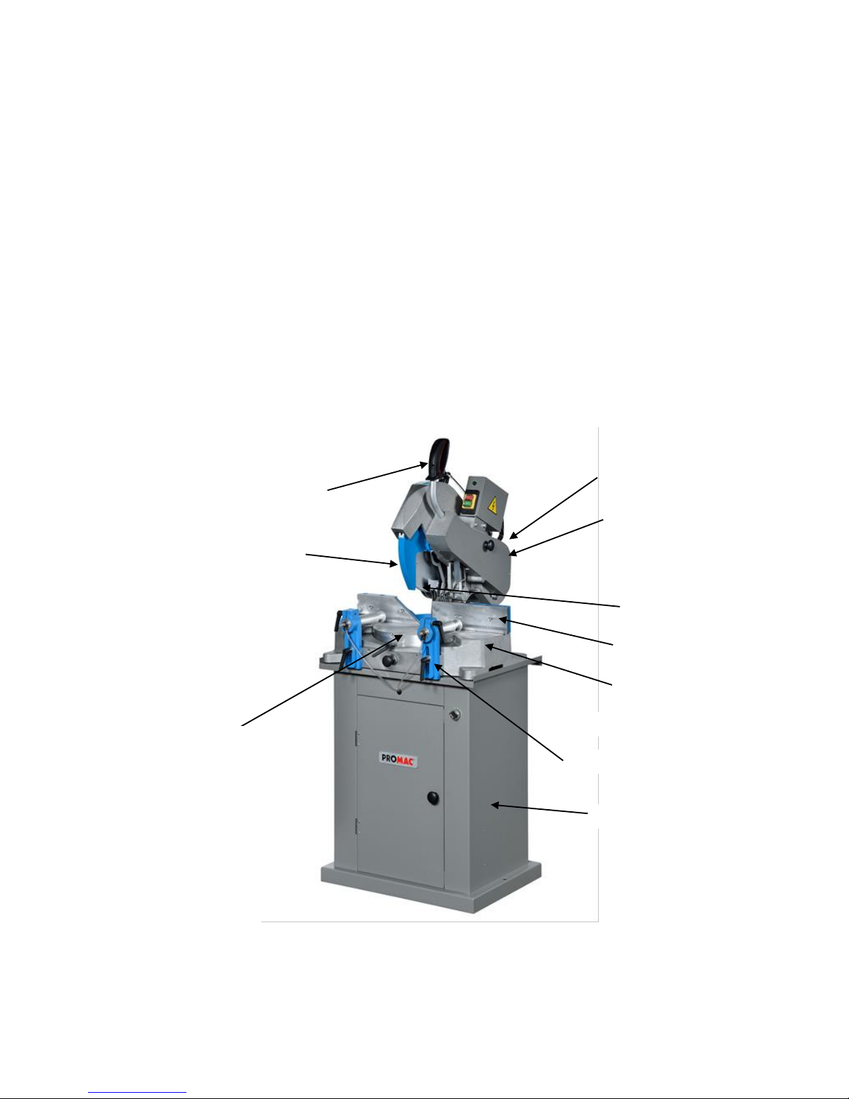
Fig 1
Table
Saw-Motor Arm
Turntable
Fences
Blade
Horizontal Vise
Internal Blade Guard
Operating handle
Motor
Base
Stand
7
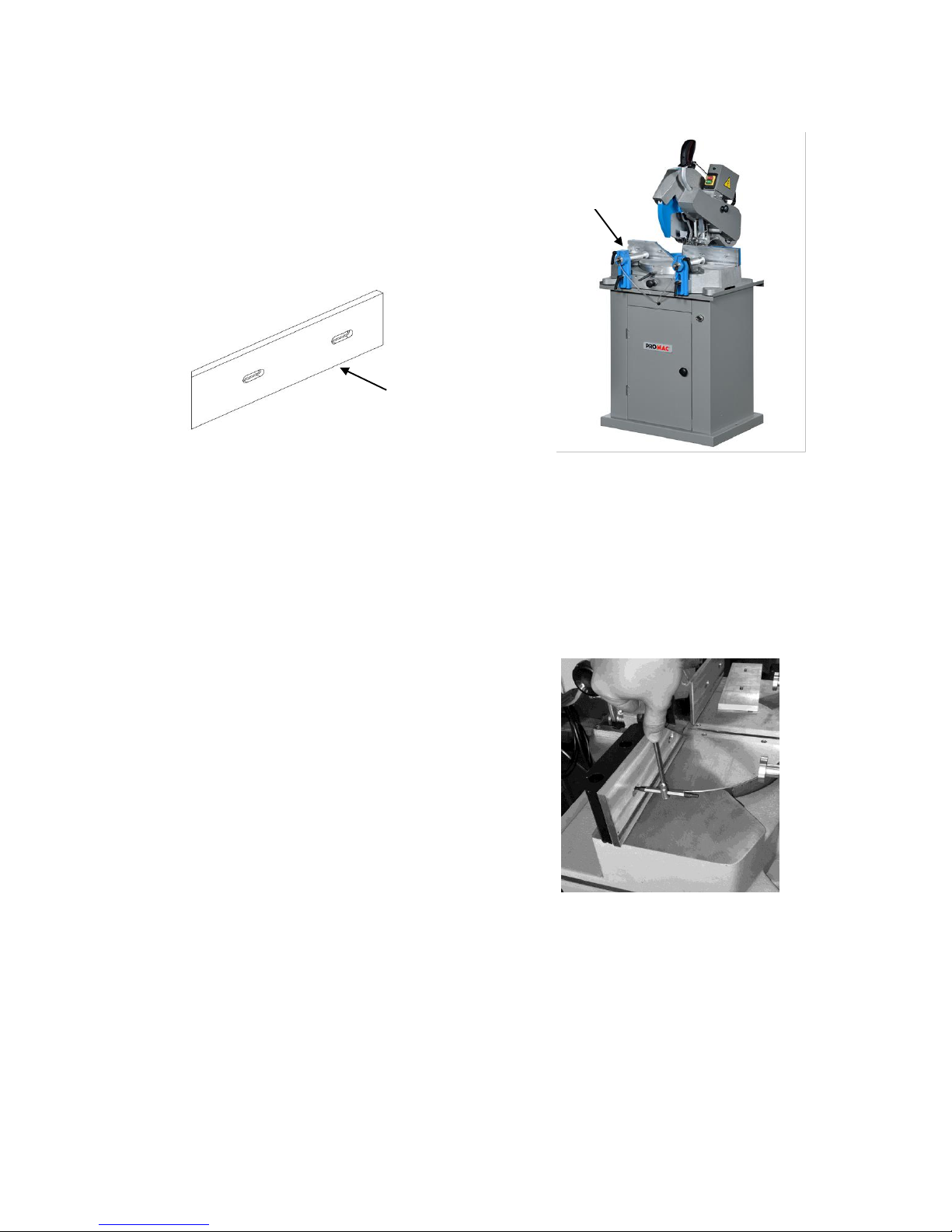
Shipping Contents
Contents of the Carton
1 Machine body (A) FIG 2
1 Backgage Seat Right Plate (B) FIG 3
1 Operating Instructions/Parts List
(not shown)
Assembly
Assembly
You will replacement an vise plate as a
parts in side of machine stand.
Attention:
The vise plate only service for 90
degree cutting (saw arm angle).
Fig 3
B
Fig 2
A
Fig 4

Controls and Indicators
Voltage & frequency of the machine
Keep this manual in a good state and
available at a close distance from the
machine.
Foreword
For the preparation of this manual, we
have considered all operations referring
to normal use and regular maintenance
of the machine. Therefore, for correct
and optimal use of the machine, it is
necessary to carefully follow the
instructions described herein. The use
of the machine should be entrusted only
to authorized and skilled personnel.
Attention: It is recommended not to
carry out any repair or intervention
unless not indicated. All operations
requiring the disassembly of machine
parts should be entrusted to specialized
technical personnel.
Warranty
The machine is guaranteed for a period
of 24 months starting from the date of
the purchase invoice. It consists of a
free of charge replacement of all
mechanical parts showing material or
manufacturing defects.
All electric and electronic components
are excluded from this warranty. The
warranty does not cover breakages or
defects arising out of external factors,
maintenance mistakes or other causes,
improper use of the machine, use of the
machine overloaded, normal wear,
assembly mistakes which we may not
be held responsible for. Replacements
are shipped ex our factory. The machine
must be returned on a free port basis,
even when covered by the warranty.
Communication
For any written or verbal communication
with the Dealer or with the Firm about
the machine, it is necessary to supply
the following information:
Machine model
Serial number
Name of the dealer from which the
machine was purchased.
Description of the defect found, if any
description of the type of operation
carried out working hours per day.
Machine identification
The machine model is identified by a
plate situated at the front of the base,
showing the following data:
Serial number
Year of manufacture
Manufacturer’s name
Use and limitations to use
The machine is for professional use and
has been designed and conceived for
cutting wooden semi-finished materials
and their sub-products and, with suitable
adaptations (a suitable blade and a
“vise” accessory plastic materials (PVC)
or light alloys (aluminum).The protection
rating of the electrical installation is IP
54. Only the user may be held
responsible for any damage arising out
of a different use of the machine other
than that indicates.
Attention:
1. In particular, the machine is not
suitable for cutting ferrous materials.
2. The machine cannot be used in
explosive environments.
Expected machine life
The expected life of the machine under
conditions of normal use and regular
maintenance is to be considered of at
least 5 years.
Machine disposal
When the machine is no longer
operative, it can be disposed of by
means of a standard disposal center for
industrial wastes, as it is classified as
standard solid waste material.
8
 Loading...