

Promac BX-840VADT Operating Instructions Manual
07-2016
BX-840VADT
Original:
GB
Operating Instructions
Translations:
D
Gebrauchsanleitung
F
Mode d´emploi
Drill Press / Säulenbohrmaschine /
Perceuse à colonne
Schweiz / Suisse
JPW (TOOL) AG
Tämperlistrasse 5
CH-8117 Fällanden Switzerland
www.promac.ch
France
TOOL France / PROMAC
57, rue du Bois Chaland, Z.I. du Bois Chaland
case postale 2935 FR-91029 Evry Cedex
www.promac.fr

CE‐ Conformity Declaration
i
CE‐ Konform
l
Déc
aration deConformité CE
tätserklärung
Product/Produkt/Produit:
DrillPressSäulenbohrmaschine
Perceuseàcolonne
BX‐840VADT
Brand/Marke/Marque:
PROMAC
Manufacturer/Hersteller/Fabricant:
JPW(Tool)AG,Tämperlistrasse5,CH‐8117Fällanden
Schweiz/Suisse/Switzerland
Weherebydeclarethatthisproductcomplieswiththeregulations
Wirerklärenhiermit,dassdiesesProduktderfolgendenRichtlinieentspricht
Parlaprésente,nousdéclaronsqueceproduitcorrespondauxdirectivessuivantes
2006/42/ECMachinery
DirectiveMaschinenrichtlinie
DirectiveMachines
2014/30/EU
electromagneticcompatibility
elektromagnetischeVerträglichkeit
compatibilitéélectromagnétique
designedinconsiderationofthestandards
undentspechendfolgenderzusätzlicherNormenentwickeltwurde
etétédéveloppédanslerespectdesnormescomplémentairessuivantes
ENISO12100:2010
EN12717:2001+A1:2009
EN60204‐1:2006+A1:2009
EN61000‐6‐2:2005
EN61000‐6‐4:2007+A1:2011
ResponsiblefortheDocumentation/Dokumentations‐Verantwortung/RésponsabilitédeDocumentation:
HansjörgMeier
HeadProduct‐Mgmt./LeiterProdukt‐Mgmt./Resp.GestiondesProduits
JPW(Tool)AG
2016‐07‐13AlainSchmid,GeneralManager
JPW(Tool)AG,Tämperlistrasse5,CH‐8117Fällanden
Schweiz/Suisse/Switzerland
2

GB - ENGLISH
3
Operating Instructions
Dear Customer,
Many thanks for the confidence you have shown in us with the purchase of your new PROMAC-machine. This manual has been
prepared for the owner and operators of a BX-840VADT drill press to promote safety during installation, operation and
maintenance procedures. Please read and understand the information contained in these operating instructions and the
accompanying documents. To obtain maximum life and efficiency from your machine, and to use the machine
manual thoroughly and f
…Table of Contents
1. Declaration of conformity
2. Warranty
3. Safety
Authorized use
General safety notes
Remaining hazards
4. Machine specifications
Technical data
Noise emission
Contents of delivery
Machine description
5. Transport and start up
Transport and installation
Assembly
Mains connection
Initial lubrication
Starting operation
6. Machine operation
Manual drilling
Micro down feed
Automatic downfeed
Tapping operation
7. Setup and adjustments
Removing the chuck and arbour
Changi
ng spindle speeds
Auto feed ove
8. Maintenance and inspection
9. Trouble shooting
Frequency inverter
10. Environmental protection
11. Available accessories
1. Declaration of conformity
On our own responsibility we hereby
declare that this product complies with
the regulations* listed on page 2.
Designed in consideration with the
standards**.
rload protection
ollow instructions carefully.
2. Warranty
The Seller guarantees that the
supplied product is free from material
defects and manufacturing faults. This
warranty does not cover any defects
which are caused, either directly or
indirectly, by incorrect use,
carelessness, accidental damage,
repair, inadequate maintenance or
cleaning and normal wear and tear.
Guarantee and/or warranty claims
must be made within twelve months
from the date of purchase (date of
invoice). Any further claims shall be
excluded.
This warr
obligations of the Seller and replaces
all previous declarations and
agreements concerning warranties.
The warranty period is valid for eight
hours of daily use. If this is exceeded,
the warranty period shall be reduced in
proportion to the excess use, but to no
less than three months.
Returning rejected goods requires the
prior express consent of the Seller and
is at the Buyer's risk and expense.
Further warranty details can be found
in the General Terms and Condi
(GTC). The GTC can be v
www.jettools.com
post upon request.
The Seller reserves the right to make
changes to the product and
accessories at any time.
3. Safety
3.1 Authorized use
This drill press is designed for drilling
wood and machinable metal and
plastic materials only.
Machining of other materials is not
permitted and may be carried out in
specific cases only after consulting
with the manufacturer.
Never cut magnesiumhigh danger of fire!
anty includes all guarantee
tions
iewed at
or can be sent by
The workpiece must allow to safely be
loaded and clamped for machining.
The proper use also includes
compliance with the operating and
maintenance instructions given in this
manual
.
The machine must be
by persons familiar with its operation
and maintenance and who are familiar
with its hazards.
The required minimum age must be
observed.
The machine must only be used in a
technically perfect condition.
When working on the machine, all
safety mechanisms and covers must
be mounted.
In addition to the safety requirements
contained in these operating
instructions and your country's
applicable regulations, you should
observe the generally recognized
te
chnical rules concerning the
opera
tion of wood- and metal-working
machines.
Any other use exceeds authorization.
In the event of unauthorized use of the
machine, the manufacturer renounces
all liability and the responsibility is
transferred exclusively to the operator.
3.2 General safety notes
Wood and metalworking machines
can be dangerous if not used properly.
Therefore the appropriate general
technical rules as well as the following
notes must be observed.
Read and understand t
instruction manual b
assembly or operation.
Keep this operating instruction close
by the machine, protected from dirt
and humidity, and pass it over to the
new owner if you part with the tool.
No changes to the machine may be
made.
safely, read this
operated only
he entire
efore attempting

Daily inspect the function and
4
existence of the safety appliances
before you start the machine.
Do not attempt operation in this case,
protect the machine by unplugging the
power cord.
Remove all loose clothing and confine
long hair.
Before operating the machine, remove
tie, rings, watches, other jewellery, and
roll up sleeves above the elbows.
Wear safety shoes; never wear leisure
shoes or sandals.
Always wear the approved working
outfit.
Do not wear gloves.
Wear goggles when working
Install the machine so that there is
sufficient space for safe operation and
workpiece handling.
Keep work area well lighted.
The machine is designed to operate in
closed rooms and must be placed
stable on a firm and levelled table
surface.
Make sure that the power cord does
not impede work and cause people to
trip.
Keep the floor around the machine
clean and free of scrap material, oil
and grease.
Never reach into the machine while it
is operating or running down.
Stay alert!
Give your work undivided attention.
Use common sense. Do not operate
the machine when you are tired.
Keep an ergonomic body position.
Maintain a balanced stance at all
times.
Do not operate the machine under the
influence of drugs, alcohol or any
medication. Be aware that medication
can change your behaviour.
Keep children and visitors a safe
distance from the work area.
Never leave a running machine
unattended.
Before you leave the workplace switch
off the machine.
Do not operate the electric tool near
inflammable liquids or gases.
Observe the fire fighting and fire alert
options, for example the fire
extinguisher operation and place.
Do not use the machine in a dump
environment and do not expose it to
rain.
Before machining, remove any nails
and other foreign bodies from the
workpiece.
Work only with well sharpened tools.
Machine only stock which rests
securely on the table.
Always close the chuck guard and
pulley cover before you start the
machine.
Remove the chuck key and wrenches
before machine operation.
Specifications regarding the maximum
or minimum size of the workpiece
must be observed.
Do not remove chips and workpiece
parts until the machine is at a standstill.
Do not stand on the machine.
Connection and repair work on the
electrical installation may be carried
out by a qualified electrician only.
Have a damaged or worn power cord
replaced immediately.
Make all machine adjustments or
maintenance with the machine
unplugged from the power source.
Never place your fingers in a position
where they could contact the drill or
other cutting tool if the work piece
should unexpectedly shift or your hand
should slip.
Secure workpiece against rotation.
Use fixtures, clamps or a vice to hold
the workpiece.
Never hold the workpiece with your
hands alone.
Whenever possible, position the work
piece to contact the left side of the
column.
If it is too short or the table is tilted,
clamp solidly to the table.
Use the table slots or clamping ledge
around the outside of the table.
When using a drill press vice, always
fasten it to the table.
Never do any works “freehand” (handholding the work piece rather than
supporting it on the table), except
when polishing.
Securely lock the head to the column
and the table bracket to the column
before operating the press.
Never move the head or the table
while the machine is running.
If a work piece overhangs the table
such that it will fall or tip if not held,
clamp it to the table or provide
auxiliary support.
Do not use wire wheels, router bits,
shaper cutters, circle cutters, or rotary
planers on this drill press.
3.3 Remaining hazards
When using the machine according to
regulations some remaining hazards
may still exist.
The rotating drill bit can cause injury.
Thrown workpieces and workpiece
parts can lead to injury.
Dust, chips and noise can be health
hazards.
Be sure to wear personal protection
gear such as safety goggles, ear
protection and dust mask. Use a
suitable dust collection system.
The use of incorrect mains supply or a
damaged power cord can lead to
injuries caused by electricity.
4. Machine specifications
4.1 Technical data
Drill capacity in steel (St37) 40mm
Tapping capacity M20
Spindle to column 264mm
Spindle travel 150mm
Spindle taper MT-4
Column diameter 115mm
Table size 560 x 475 mm
T-slot size 16mm
Distance spindle nose / table 600mm
Distance spindle nose / base 1130mm
Number of speeds variable
Range of speeds I 65 – 540 rpm
Range of speeds II 245 – 2000 rpm
Automatic downfeeds
0,05 / 0,1 / 0,2 mm/rev
Coolant tank volume 8 Liter
Coolant pump 72 W
Overall L/W/H
915x560x1970 mm
Net weight 382 kg
Mains 400V ~3L/PE 50Hz
Output power 1.5 kW (2 HP) S1
Reference current 3,7 A
Extension cord (H07RN-F)4x1.5mm²
Installation fuse protection 10A
4.2 Noise emission
5
(Inspection tolerance 4 dB)
Acoustic pressure level
(according to EN ISO 11202):
Idling LpA 69,6 dB(A)
In operation LpA 79,0 dB(A)
The specified values are emission
levels and are not necessarily to be
seen as safe operating levels.
As workplace conditions vary, this
information is intended to allow the
user to make a better estimation of the
hazards and risks involved only.
4.3 Content of delivery
16mm keyless chuck, B18
MT-4 / B18 arbour
Chuck guard
Table ris
Coolant facility
Drift key
Operating tools
Assembly kit
Operating manual
Spare parts list.
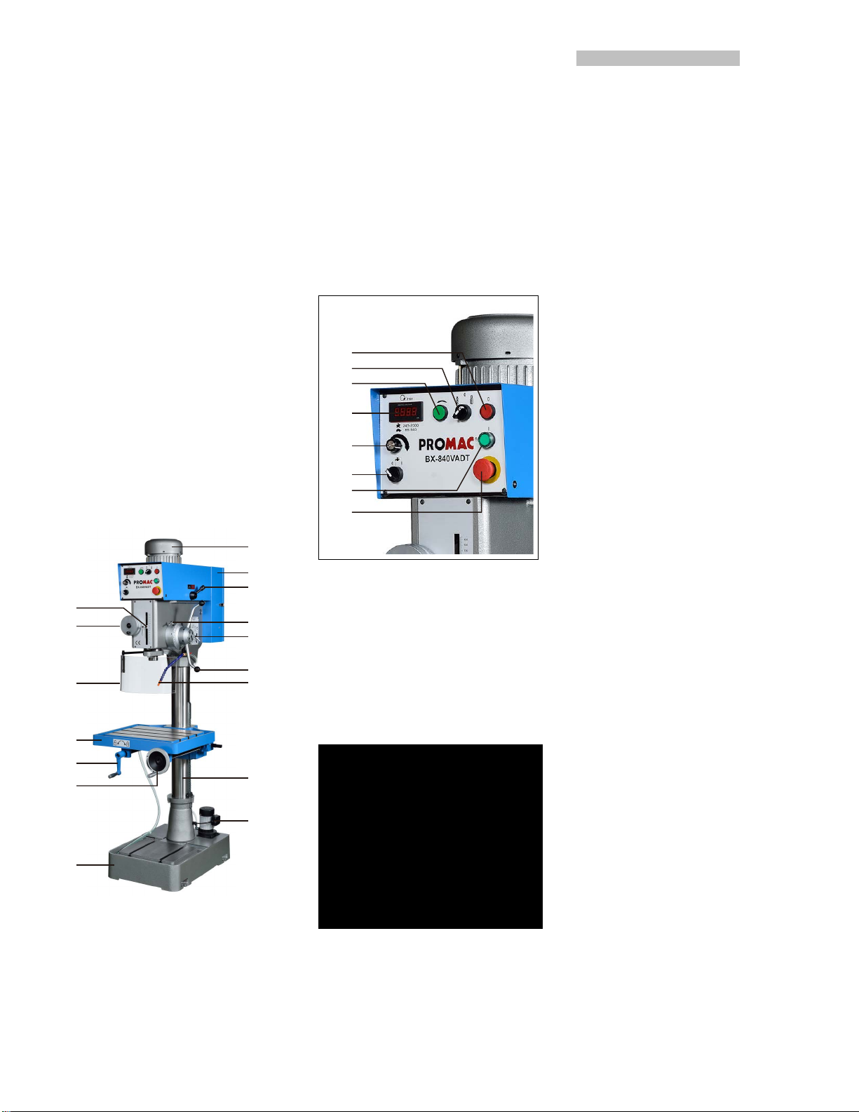
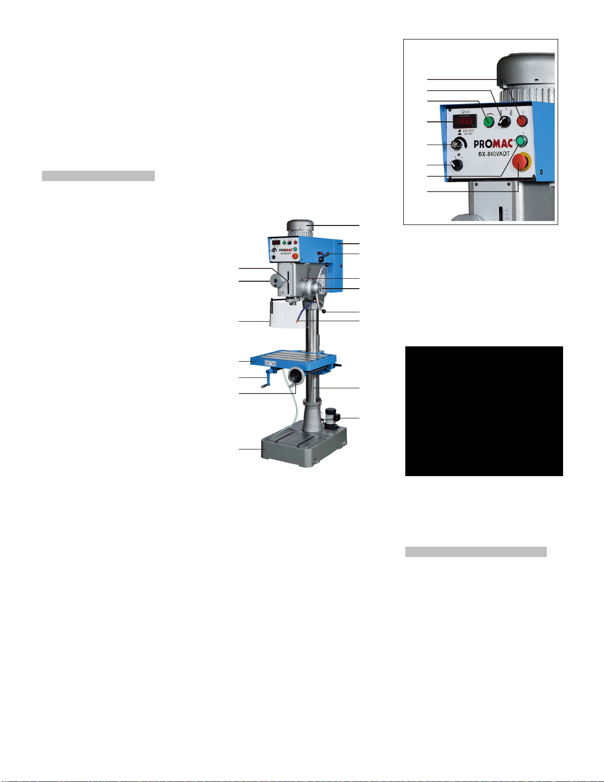
4.4 Description of the machine
ing crank (2x)
A
B
C
Q
P
D
E
F
O
G
M
L
K
H
A…...Motor
B…..Electric Box
C….High / Low speed select switch
D….Scale ring lock knob
E….Down feed handle lock
F….Down feed handles
G….Coolant nozzle
H….Rack
I…...Coolant pump
J…..Base with coolant tank
K….Table lifting handwheel
L…..Table locking handle
M….Working table
O….Chuck guard
P….Micro feeding handwheel
Q….Drill / Tap depth stop
R
S
T
U
V
W
X
Y
Fig 2
R….Spindle OFF-button
S….Drill / Tap select switch
T….Spindle reverse jog-button
U….Digital readout
V….Variable speed select knob
W…Coolant On/Off switch
X….Spindle ON-button
Y….Emergency stop button
5. Transport and start up
5.1 Transport and installation
The machine will be delivered in a
closed crate.
For transport use a forklift or hand
trolley. Make sure the machine does
not tip or fall off during transport.
Danger of tipping due to high gravity
center!
The machine is designed to operate in
closed rooms.and must be placed
stable on a firm and levelled ground.
A minimum distance of 800mm
towards a rear wall must be kept (for
access to the electrical box).
The machine
acking reasons the machine is
For p
not completely assembled.
5.2 Assembly
If you notice transport damage while
unpacking, notify your supplier
immediately. Do not operate the
machine!
Dispose of the packing in an
environmentally friendly manner.
Clean all rust protected surfaces with
a mild solvent e.g. petroleum.
(Note: lacquer thinner or similar can
destroy the paint).
Attach the table lifting handwheel (K)
and the table locking handle (L).
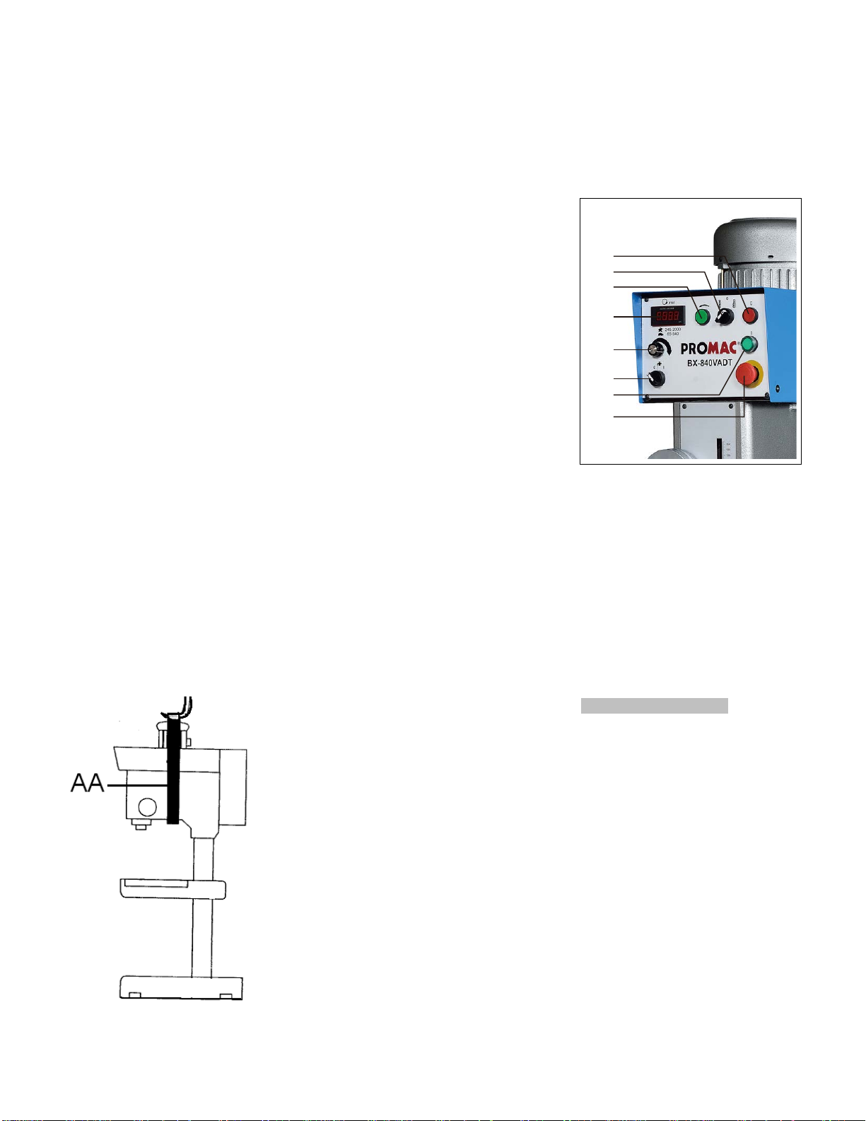
Mounting machine to the floor:
Unbol
t the machine from
crate.
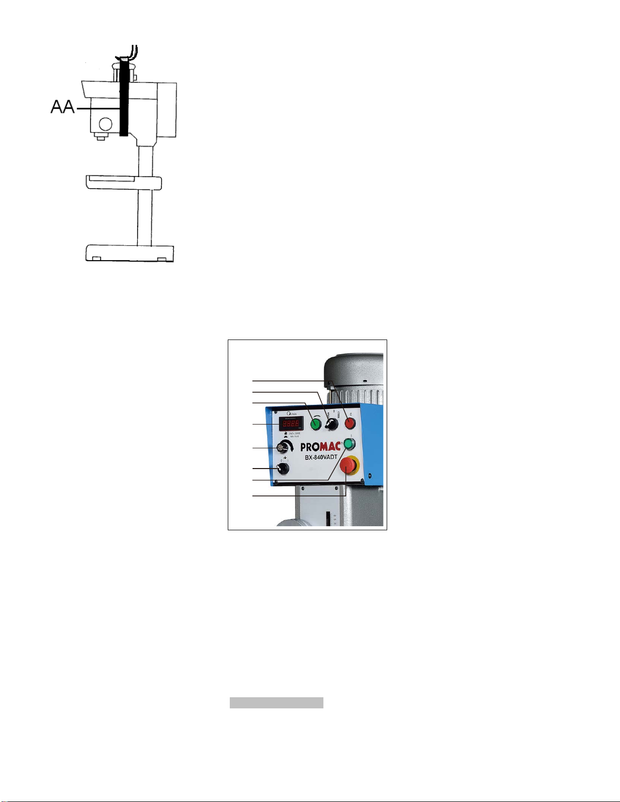
Use heavy duty fibre belts (AA, Fig 4)
for lifting the machine off the pallet.
must be bolted down.
the shipping
I
J
Fig 1
Fig 3
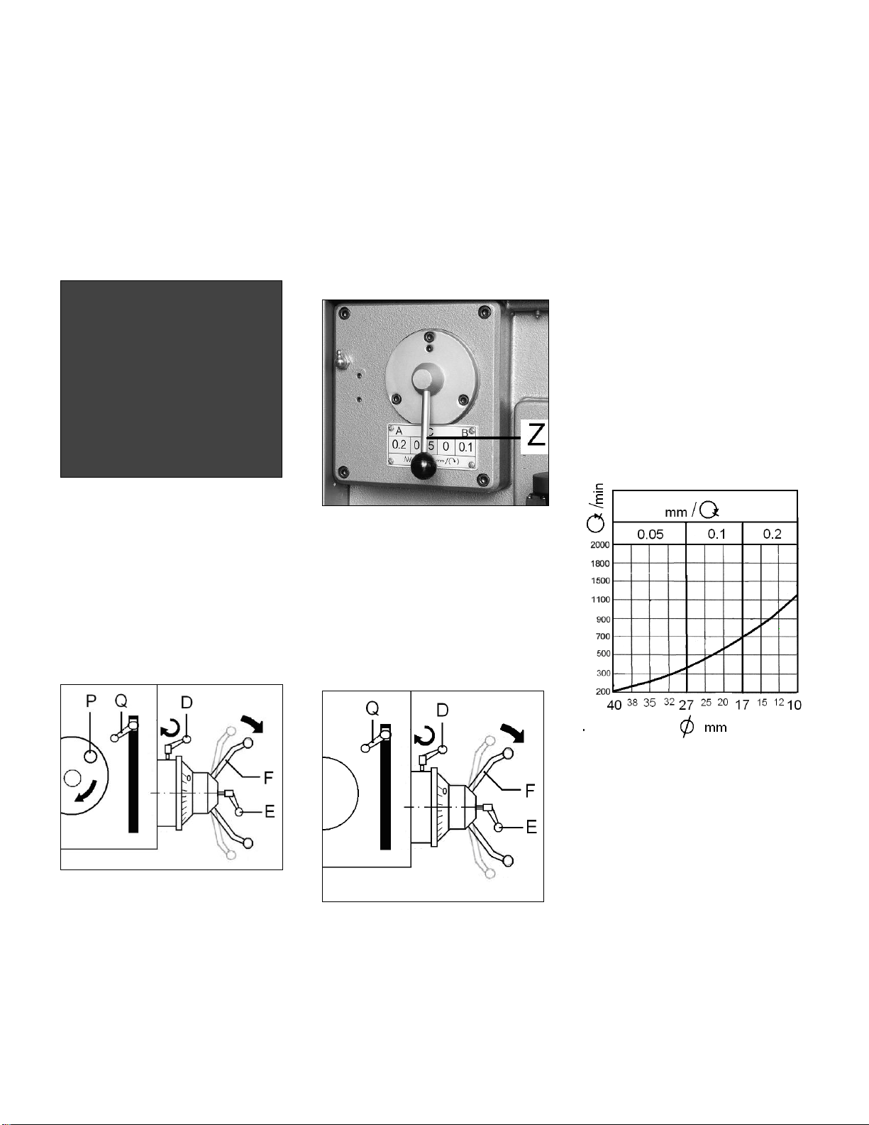
Z…Feed select switch
6
Fig 4
Caution:
The machine is heavy! 382kg
Assure the sufficient load capacity
and proper condition of your lifting
devices.
Never step underneath suspended
loads.
Carefully place the machine to the
floor.
Use 4 anchor bolts of sufficient size
and length.
Use a machinist’s precision level to
make sure that the machine table is
level.
Loosen mounting bolts, shim and
tighten mounting bolts if needed.
The machine must be level to be
accurate.
5.3 Mains connection
Mains connection and any extension
c
ords used must comply with
applicable regulations.
The mains voltage must comply with
the information on the machine licence
plate.
The mains connection must have a
10 A surge-proof fuse.
Only use power cords marked H07RNF
Connections and repairs to the
electrical equipment may only be
carried out by qualified electricians.
ATTENTION:
- If the direction of rotation is not
correct, the phase converter inside the
CCE Euro plug must be pushed
turned
180°.
5.4 Initial lubrication
The machine must be serviced at all
lubrication points before it is placed
into service!
Failure to comply may cause serious
damage.
(see chapter 8 for lubrication)
The coolant tank has to be filled with
coolant.
5.4 Starting operation
Before starting the machine check
the proper chucking.
You can start the machine with the
green ON-button (X, Fig 5).
The red OFF-button (R) stops the
machine.
in and
R
S
T
U
V
W
X
Y
Fig 5
The emergency stop button (Y) stop
all mach
Attention:
The machine still has electric power!
Turn emergency stop button clockwise
to reset.
Use the variable speed select knob (V)
to set the speed.
The digital readout (U) shows the
spindle speed.
6. Machine operation
Always adjust the table and the depth
stop to prevent drilling into the table or
vise.
ine functions.
s
Secure workpiece to the table with
clamps or a vice to prevent rotating
with the drill bit.
T-slot size is 16mm.
Feed the bit into the material with only
enough force to allow the drill bit to
work.
Feeding too slowly may cause burning
of the workpiece.
Feeding too quickly may cause the
motor to stop and/or the drill bit to
break.
Recommended spe
HSS drill:
: 2000 RPM
Wood
Plastic: 1500 RPM
Aluminium: 1500 RPM
Brass: 1500 RPM
Cast iron: 1000 RPM
Mild steel: 800 RPM
High carbon steel: 600 RPM
Stainless steel: 300 RPM
Generally speaking, the smaller in
relation the drill bit, the greater the
RPM required.
Wood requires higher speeds than
metal.
Metal is usually drilled at slower
speeds; cutting oil is applied if
necessary.
Warning:
Always keep your hands well clear of
the rotating bit.
Never place your fingers in a position
where they could contact any ro
, chuck or cutting chips.
tool
Do not remove chips and workpiece
parts until the machine is at a standstill.
Always close the chuck guard and
pulley cover before you start the
machine.
When using a drill press vice, always
fasten it to the table.
Never do any works “freehand” (handholding the work piece rather than
supporting it on the table), except
when polishing.
Support long workpieces with helping
roller stands.
Do not use wire wheels, router bits,
shaper cutters, circle cutters, o
planers o
Never cut magnesiumhigh danger of fire!
n this drill press.
eds for a 10mm
tating
r rotary
In case of danger push the
7
emergency stop button.
Machine at rest:
If the drill press is not used for a
longer time, pull the mains plug and
protect all blanc surfaces.
6.1 Manual drilling
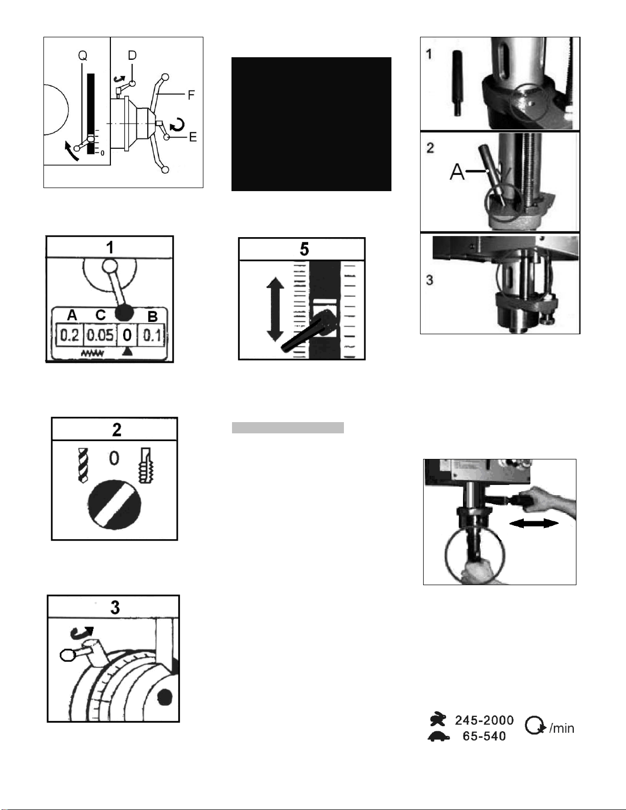
Set the feed select switch (Z, Fig 3) to
“0“ position.
Tighten the downfeed handle lock
knob (E, Fig 6).
Fig 6
Loosen the scale ring lock knob (D).
Set the depth stop (Q) to the desired
position.
6.2 Micro down feed
Set the feed select switch (Z, Fig 3) to
“0“ position.
Move the depth stop (Q, Fig 7) to the
highest position.
Engage the feed mechanism by
pushing out the down feed handles (F).
Rotate the micro-feeding hand wheel
(P).
The spindle will feed down until the set
drill depth has been reached.
The feed will disengage and the
spindle will return to the top by spring
force.
6.3 Automatic down feed
Adjust the desired power down feed (Z,
Fig 8).
Fig 8
Loosen the downfeed handle lock
knob (E, Fig 9).
Move the depth stop (Q, Fig 7) to the
highest position.
Engage the feed mechanism by
pushing out the down feed handles (F).
The spindle will feed down
automatically until the drill depth has
been reached.
The auto feed will disengage and the
spindle will return to the top by spring
force.
CAUTION:
Do not let feeding depth exceed
spindle stroke.
If not in use, disengage the power
down feed mechanism.
Set the auto-feed select switch (Z, Fig
3) to “0“ position.
Reference values for feed speed
The feed speed depends on the drill
bit diameter and the material of the
workpiece.
The larger the drill bit and the harder
the workpiece, the lower the feed
speed and the lower the spindle rpm.
HSS-drill bit in material steel (C15):
Fig 10
6.4 Tapping operation
For tapping operations the spindle
speed must be below 150 rpm.
The machine setup must be as follows.
Fig 7
Loosen the downfeed handle lock
knob (E).
Lower the spindle until the drill bit
touches the workpiece.
Rotate the scale ring to the desired
drill depth and tighten the lock knob
(D).
Fig 9
Lower the spindle until the drill bit
touches the workpiece.
Rotate the scale ring to the desired
drill depth and tighten the lock knob
(D).
Start the machine (X, Fig 5)
4) Tighten the downfeed handle lock
8
knob (E, Fig 11).
Fig 11
1) Set the feed select switch (Z, Fig 3)
to “0“ position.
2) Set the select switch (S, Fig 2) to
the “Tapping“ position.
3) Loosen the scale ring lock knob (D,
Fig 11).
5) Set the depth stop (Q) to the
desired position.
The spindle will auto-reverse at this
point.
7. Setup and adjustments
General note:
Setup and adjustment work may
only be carried out after the
machine is protected against
accidental starting.
Push the E-stop button, pull the
mains plug!
7.1 Removing the Chuck and Arbour
Disconnect from the power source.
Push the E-stop button!
Lower the quill using the down feed
handle.
Lock the quill in lowered position by
installing the supplied index pin (A, Fig
12).
Fig 12
Rotate the spindle to align the key in
the spindle with the key hole in the
quill.
Insert the drift key into the aligned
slots and tap lightly.
We recommend using the rapid drift
key (Fig 13).
article number: 10002086
Fig 13
Hold the chuck and arbour assembly
by hand (or a protected table) as it
falls away from the spindle.
7.2 Changing Spindle Speeds
Two different speed ranges can be
selected on the gearbox (C, Fig 1).
Use the variable speed select knob (V,
9
Fig 2) to set the spindle speed.
The digital readout (U) displays the
actual speed.
7.3 Auto feed overload protection
The auto feed mechanism is equipped
with an overload protection clutch.
First the downfeed will stop, then the
feed handles will disengage and the
spindle will return to the top by spring
force.
Stop the machine immediately under
this condition.
Check the job-setup:
Make sure that the drill bit is sharp and
the machine adjustments are correct.
Adjustment:
The overload protection clutch has
precisely been adjusted ex works and
may only be readjusted by a qualified
person.
If the job setup is correct and the
overload clutch reacts, it may be
adjusted as follows:
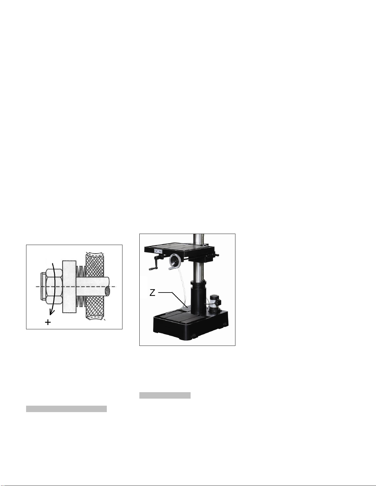
Remove the „overload
protection“ cover plate.
Tighten the nut clockwise by ¼ turn
(Fig 14).
Fig 14
Test the auto feed drilling performance.
If needed, repeat the adjustment.
Reinstall the cover plate.
ATTENTION:
Over tightening the clutch may
damage the feed mechanism.
8. Maintenance and inspection
General notes:
Maintenance, cleaning and repair
work may only be carried out after
the machine is disconnected from
the power source. Pull the mains
plug!
Clean the machine regularly.
Defective safety devices must be
replaced immediately.
Repair and maintenance work on the
electrical system may only be carried
out by a qualified electrician.
Changing oil:
Drain oil after first month of operation.
by removing drain plug and refill with
oil.
Gear box oil (SAE 90)
Then change the oil annually
(respectively every 700 operating
hours).
Weekly lubrication:
Once a week lubricate gently with
grease.
-the teeth of the quill
-the column-rack
Coolant facility:
Pour 8 litres of coolant mix into the
coolant tank (Z, Fig 15).
Fig 15
Follow coolant manufacturer’s
recommendations for use, care and
disposal.
9. Trouble shooting
Motor doesn’t start
*No electricitycheck mains and fuse.
*Defective switch, motor or cordconsult an electrician.
*Inverter Failuresee chapter 9.1
Chuck will not stay on spindle
*Oil or grease on contact surfacesclean the tapered surfaces of chuck
and spindle.
Machine vibration
*Dry spindle quilllubricate spindle quill.
*dull drill bitresharpen drill bit.
Drill bit burns
*incorrect speedreduce speed.
*Chips cloggedretract drill bit frequently
*dull drill bitresharpen drill bit.
*feeding too slowfeed faster.
Drill leads off
*cutting lips or angle not equalresharpen drill bit correctly.
*drilled hole off centredrill a pilot hole first.
*bent drill bituse a proper drill bit.
*drill bit not properly installedinstall drill bit correctly.
9.1 Frequency inverter
Installation and repair of the frequency
inverter may only be carried out by a
qualified electrician.
The following points have to be
observed:
1) Disconnected from the power
source. Pull the mains plug!
2) Electronic components are very
sensitive, do not touch with bare
hands or non-isolated metal tools.
3) The DC-capacitor remains under
voltage, even when the machine is
disconnected from mains.
Assure that all LED´s are off before
you start service work.
4) Avoid electrostatic charging.
Ground connect the inverter baseplate.
5) Never connect to motor output
terminals (U/V/W) to the main power
supply (AC).
6) The frequency inverter is equipped
with diagnostic software.
The machine will stop and the error
code will be displayed on the LED
display.
Push the “Reset” button to restart the
frequency inverter.

Error codes:
10
o.H.
* Inverter over temperatureInspect ventilation holes and cooling
fins for dust and debris
o.L / o.L. I / o.L.2
* Motor overloaded.Reduce motor load.
O.C. / o.c.A. / o.c.n. / o.c.d.
* Abnormal currant increaseInspect motor connection and isolation.
c.F.I / c.F.2 / c.F.3
* Inverter internal errorStop the machine and restart.
C.F.F.
* Fuse failure, ground failureInspect the power supply, fuses and
ground connection
Stop the machine and restart.
10. Environmental protection
Protect the environment.
Your appliance contains valuable
materials which can be recovered or
recycled. Please leave it at a
specialized institution.
11. Available accessories
Refer to the PROMAC Pricelist.

DE - DEUTSCH
11
Gebrauchsanleitung
Sehr geehrter Kunde,
vielen Dank für das Vertrauen, welches Sie uns beim Kauf Ihrer neuen PROMAC-Maschine entgegengebracht haben. Diese Anleitung
ist für den Inhaber und die Bediener zum Zweck einer sicheren Inbetriebnahme, Bedienung und Wartung der Bohrmaschine
%;-840VADT erstellt worden. Beachten Sie bitte die Informationen dieser Gebrauchsanleitung und der beiliegenden
Dokumente. Lesen Sie diese Anleitung vollständig, insbesondere die Sicherheitshinweise, bevor Sie die Maschine
zusammenbauen, in Betrieb nehmen oder warten. Um eine maximale Lebensdauer und Leistungsfähigkeit Ihrer Maschine zu
erreichen befolgen Sie bitte sorgfältig die Anweisungen.
Inhaltsverzeichnis
1. Konformitätserklärung
2. Garantieleistungen
3. Sicherheit
Bestimmungsgemäße Verwendung
Allgemeine Sicherheitshinweise
Restrisiken
4. Maschinenspezifikation
Technische Daten
Schallemission
Lieferumfang
Beschreibung der Maschine
5. Transport und Inbetriebnahme
Transport und Aufstellung
Montage
Elektrischer Anschluss
Erstschmierung
Inbetriebnahme
6. Betrieb der Maschine
Manueller Pinolenvorschub
Pinolen Feinvorschub
Automatischer Pinolenvorschub
Gewindeschneiden
7. Rüst- und Einstellarbeiten
Bohrfutterwechsel
Drehzahlwechsel
Vorschub Überlastschutz
8. Wartung und Inspektion
9. Störungsabhilfe
10. Umweltschutz
11. Lieferbares Zubehör
1. Konformitätserklärung
Wir erklären in alleiniger
Verantwortlichkeit, dass dieses
Produkt mit den auf Seite 2
angegebenen Richtlinien*
übereinstimmt.
Bei der Konstruktion wurden folgende
Normen** berücksichtigt.
2. Garantieleistungen
Der Verkäufer garantiert, dass das
gelieferte Produkt frei von Materialund Fertigungsfehlern ist. Diese
Garantie trifft nicht auf jene Defekte zu,
welche auf direkten oder indirekten,
nicht fachgerechten Gebrauch,
Unachtsamkeit, Unfallschaden,
Reparatur, mangelhafte Wartung bzw.
Reinigung sowie normalen Verschleiß
zurückzuführen sind.
Garantie- bzw. Gewährleistungsansprüche müssen innerhalb von 12
Monaten ab dem Verkaufsdatum
(Rechnungsdatum) geltend gemacht
werden. Weitergehende Ansprüche
sind ausgeschlossen.
Die vorliegende Garantie umfasst
sämtliche Garantieverpflichtungen
seitens des Verkäufers und ersetzt
alle früheren Erklärungen und
Vereinbarungen betreffend Garantien.
Die Garantiefrist gilt für eine tägliche
Betriebszeit von 8 Stunden. Wird
diese überschritten, so verkürzt sich
die Garantiefrist proportional zur
Überschreitung, jedoch höchstens auf
3 Monate.
Die Rücksendung beanstandeter
Ware bedarf der ausdrücklichen
vorherigen Zustimmung vom
Verkäufer und geht auf Kosten und
Gefahr des Käufers.
Die ausführlichen Garantieleistungen
sind den Allgemeinen
Geschäftsbedingungen (AGB) zu
entnehmen. Die AGB sind unter
www.jettools.com einzusehen oder
werden auf Anfrage per Post zugestellt.
Der Verkäufer behält sich das Recht
vor, jederzeit Änderungen am Produkt
und Zubehör vorzunehmen.
3. Sicherheit
3.1 Bestimmungsgemäße
Verwendung
Diese Ständerbohrmaschine ist
ausschließlich zum Bohren von Holz
und zerspanbaren Kunststoffen und
Metallen geeignet.
Die Bearbeitung anderer Werkstoffe
ist nicht zulässig bzw. darf in
Sonderfällen nur nach Rücksprache
mit dem Maschinenhersteller erfolgen.
Niemals Magnesium zerspanenHohe Feuergefahr!
Es dürfen nur Werkstücke bearbeitet
werden welche sicher aufgelegt und
gespannt werden können.
Die bestimmungsgemäße
Verwendung beinhaltet auch die
Einhaltung der vom Hersteller
angegebenen Betriebs- und
Wartungsanweisungen.
Die Maschine darf ausschließlich von
Personen bedient werden, die mit
Betrieb und Wartung vertraut und über
die Gefahren unterrichtet sind.
Das gesetzliche Mindestalter ist
einzuhalten.
Die Maschine nur in technisch
einwandfreiem Zustand mit montierten
Schutzeinrichtungen betreiben.
Neben den in der Gebrauchsanleitung
enthaltenen Sicherheitshinweisen und
den besonderen Vorschriften Ihres
Landes sind die für den Betrieb von
Holz- und Metallbearbeitungsmaschinen allgemein
anerkannten fachtechnischen Regeln
zu beachten.
Jeder darüber hinaus gehende
Gebrauch gilt als nicht
bestimmungsgemäß und für daraus
resultierende Schäden haftet der
Hersteller nicht. Das Risiko trägt allein
der Benutzer.
3.2 Allgemeine Sicherheitshinweise

12
Holz- und
Metallbearbeitungsmaschinen können
bei unsachgemäßem Gebrauch
gefährlich sein. Deshalb ist zum
sicheren Betreiben die Beachtung der
zutreffenden UnfallverhütungsVorschriften und der nachfolgenden
Hinweise erforderlich.
Lesen und verstehen Sie die
komplette Gebrauchsanleitung bevor
Sie mit Montage oder Betrieb der
Maschine beginnen.
Bewahren Sie die
Bedienungsanleitung, geschützt vor
Schmutz und Feuchtigkeit, bei der
Maschine auf, und geben Sie sie an
einen neuen Eigentümer weiter.
An der Maschine dürfen keine
Veränderungen, An- und Umbauten
vorgenommen werden.
Überprüfen Sie täglich vor dem
Einschalten der Maschine die
einwandfreie Funktion und das
Vorhandensein der erforderlichen
Schutzeinrichtungen.
Festgestellte Mängel an der Maschine
oder den Sicherheitseinrichtungen
sind zu melden und von den
beauftragten Personen zu beheben.
Nehmen Sie die Maschine in solchen
Fällen nicht in Betrieb, sichern Sie die
Maschine gegen Einschalten durch
Ziehen des Netzsteckers.
Zum Schutz von langem Kopfhaar
Mütze oder Haarnetz aufsetzen.
Enganliegende Kleidung tragen,
Schmuck, Ringe und Armbanduhren
ablegen.
Tragen Sie Schutzschuhe, keinesfalls
Freizeitschuhe oder Sandalen.
Verwenden Sie die durch Vorschriften
geforderte persönliche
Schutzausrüstung.
Beim Arbeiten an der Maschine keine
Handschuhe tragen.
Beim Arbeiten Schutzbrille tragen.
Die Maschine so aufstellen, dass
genügend Platz zum Bedienen und
zum Führen der Werkstücke gegeben
ist.
Sorgen Sie für gute Beleuchtung.
Achten Sie darauf, dass die Maschine
standsicher auf fester und ebener
Tischfläche steht.
Beachten Sie dass die elektrische
Zuleitung nicht den Arbeitsablauf
behindert und nicht zur Stolperstelle
wird.
Den Arbeitsplatz frei von
behindernden Werkstücken, etc.
halten.
Niemals in die laufende Maschine
greifen.
Seien Sie aufmerksam und
konzentriert. Gehen Sie mit Vernunft
an die Arbeit.
Achten Sie auf ergonomische
Körperhaltung.
Sorgen Sie für sicheren Stand und
halten Sie jederzeit das Gleichgewicht.
Arbeiten Sie niemals unter dem
Einfluss von Rauschmitteln wie
Alkohol und Drogen an der Maschine.
Beachten Sie, dass auch
Medikamente Einfluss auf Ihr
Verhalten nehmen können.
Halten Sie Unbeteiligte, insbesondere
Kinder vom Gefahrenbereich fern.
Die laufende Maschine nie
unbeaufsichtigt lassen.
Vor dem Verlassen des Arbeitsplatzes
die Maschine ausschalten.
Benützen Sie die Maschine nicht in
der Nähe von brennbaren
Flüssigkeiten oder Gasen.
Beachten Sie die Brandmelde- und
Brandbekämpfungsmöglichkeiten z.B.
Standort und Bedienung von
Feuerlöschern.
Benützen Sie die Maschine nicht in
feuchter Umgebung und setzen Sie
sie nicht dem Regen aus.
Vor der Bearbeitung Nägel und andere
Fremdkörper aus dem Werkstück
entfernen.
Nur mit gut geschärften Werkzeugen
arbeiten.
Bearbeiten Sie nur ein Werkstück, das
sicher auf dem Tisch aufliegt.
Arbeiten Sie nie bei geöffnetem
Bohrfutterschutz oder Riemenschutz.
Entfernen Sie vor dem Start den
Bohrfutterschlüssel und andere
Werkzeuge.
Angaben über die min. und max.
Werkstückabmessungen müssen
eingehalten werden.
Späne und Werkstückteile nur bei
stehender Maschine entfernen.
Nicht auf der Maschine stehen.
Arbeiten an der elektrischen
Ausrüstung der Maschine dürfen nur
durch eine Elektrofachkraft
vorgenommen werden.
Tauschen Sie ein beschädigtes
Netzkabel sofort aus.
Umrüst-, Einstell- und
Reinigungsarbeiten nur im
Maschinenstillstand und bei
gezogenem Netzstecker vornehmen.
Halten Sie mit ihren Fingern
ausreichend Abstand zum rotierenden
Bohrwerkzeug, beachten Sei dass das
Werkstück oder Ihre Hände
verrutschen können.
Sichern Sie das Werkstück gegen
Mitdrehen.
Verwenden Sie Spannpratzen, einen
Schraubstock oder eine
Hilfsvorrichtung um das Werkstück zu
fixieren.
Halten Sie das Werkstück niemals mit
den Händen allein.
Wenn immer möglich stützen Sie das
Werkstück an der Säule gegen
Verdrehung ab.
Falls das Werkstück dazu zu kurz ist
oder der Tisch geschwenkt wurde
klemmen Sie das Werkstück am Tisch
fest.
Verwenden Sie dazu die Tischnuten
oder eine außen angesetzte
Schraubzwinge.
Den Schraubstock immer am Tisch
festschrauben.
Arbeiten Sie niemals freihändig (frei
gehaltenes Werkstück ohne
Abstützung am Tisch), außer bei
Polierarbeiten.
Überprüfen Sie die korrekte
Befestigung des Bohrkopfes und des
Bohrtisches bevor Sie mit der
Maschine arbeiten.
Führen Sie bei laufender Maschine
keine Verstellungen am Bohrkopf und
am Bohrtisch durch.
Falls die Schwerpunktlage des
Werkstückes außerhalb des Tisches
liegt klemmen Sie es am Tisch fest
oder stützen Sie es mit einem
Rollbock ab.
Verwenden Sie keine
Drahtbürstwerkzeuge, Fräswerkzeuge,
Kreisschneider und Schleifscheiben
auf dieser Maschine.
3.3 Restrisiken
Auch bei vorschriftsmäßiger
Benutzung der Maschine bestehen die
nachfolgend aufgeführten Restrisiken.
Verletzungsgefahr durch den
rotierenden Bohrer.
Gefährdung durch wegfliegende
13
Werkstücke und Werkstückteile.
Gefährdung durch Lärm und Staub.
Unbedingt persönliche
Schutzausrüstungen wie Augen-,
Gehör- und Staubschutz tragen.
Eine geeignete Absauganlage
einsetzen!
Gefährdung durch Strom, bei nicht
ordnungsgemäßer Verkabelung.
4. Maschinenspezifikation
4.1 Technische Daten
Bohrkapazität in Stahl (St-37) 40mm
Gewindekapazität M20
Ausladung 264mm
Bohrhub 150mm
Spindelaufnahme MK-4
Säulendurchmesser 115mm
Tischgröße 560 x 475 mm
Tisch T-Nutgrösse 16mm
Distanz Spindelnase-Tisch 600mm
Distanz Spindelnase-Fuß 1130mm
Drehzahlen stufenlos
Drehzahlbereich I 65 – 540 U/min
Drehzahlbereich II 245 – 2000 U/min
Automatischer Pinolenvorschub
0,05 / 0,1 / 0,2 mm/U
Kühlmittelbehälter 8 Liter
Kühlmittelpumpe 72 W
Maschinenabm
915
Maschinengewicht 382 kg
Netzanschluss 400V ~3L/PE 50Hz
Abgabeleistung 1.5 kW (2 PS) S1
Betriebsstrom 3,7 A
Anschlussleitung (H07RN-F)4x1.5mm²
Bauseitige Absicherung 10A
4.2 Schallemission
(Messunsicherheitsfaktor 4 dB)
Schalldruckpegel
( nach EN ISO 11202):
Leerlauf LpA 69,6 dB(A)
Bearbeitung LpA 79,0 dB(A)
Die angegebenen Werte sind
Emissionspegel und sind nicht
notwendigerweise Pegel für sicheres
Arbeiten.
Sie sollen dem Anwender eine
Abschätzung der Gefährdung und des
Risikos ermöglichen.
essung (LxBxH)
x560x1970 mm
4.3 Lieferu
16mm Schnell
Aufnahmedorn MK-4 / B18
Bohrfutterschutz
Tischkurbel (2x)
Kühlmitteleinrichtung
Auswurfkeil
Bedienwerkzeug
Montagezubehör
Gebrauchsanleitung
Ersatzteilliste
4.4 Beschreibung der Maschine
mfang
spannbohrfutter, B18
Q
P
O
M
L
K
J
Fig 1
A…...Motor
B…..Elektro Schaltschrank
C….Schaltgriff Vorgelege
D….Bohr-Tiefenanschlag
E….Feinvorschub-Feststellhebel
F….Bohrvorschub Handgriffe
G….Kühlmitteldüse
H….Zahnstange
I…..Kühlmittelpumpe
J….Fuss mit Kühlmitteltank
K….Tisch-Höhenkurbel
L…..Tisch-Klemmung
M….Arbeitstisch
O….Bohrfut
P….F
Q….Gewinde-Tiefenanschlag
terschutz
einvorschub-Handrad
R
S
T
U
V
W
X
Y
A
B
C
D
E
F
G
R….Spindel Aus-Taster
S….Wahlschalter Bohren / Gewinde
T….Spindel Umkehrtaste
U….Digitale Drehzahlanzeige
V….Drehzahl Wahlknopf
W…Kühlmittel Ein / Aus Schalter
X….Spindel Ein-Taster
Y….Not-Aus Taster
Fig 2
H
I
Fig 3
Z….Bohrvorschub Schalthebel
5. Transport und Inbetriebnahme
5.1. Transport und Aufstellung
Die Maschine wird geschlossen auf
Palette geliefert.
Zum Transport verwenden Sie einen
handelsüblichen Stapler oder
Hubwagen. Sichern Sie die Maschine
beim Transport gegen Umfallen.
Die Maschine ist stark kopflastig, beim
Transport besteht Kippgefahr!
Die Aufstellung der Maschine sollte in
geschlossenen Räumen erfolgen,
werkstattübliche Bedingungen sind
dabei ausreichend.
Ein Abstand von 800mm zu einer
14
rückwärtigen Wand darf nicht
unterschritten werden (für Zugang zu
Elektro-Schaltkasten).
Die Aufstellfläche muss ausreichend
eben und belastungsfähig sein.
Die Maschine muss auf der
Aufstellfläche festgeschraubt werden.
Aus verpackungstechnischen Gründen
ist die Maschine nicht komplett
montiert.
5.2 Montage
Wenn Sie beim Auspacken einen
Transportschaden feststellen,
benachrichtigen Sie umgehend Ihren
Händler, nehmen Sie das Gerät nicht
in Betrieb.
Entsorgen Sie die Verpackung bitte
umwe
ltgerecht.
Entfer
nen Sie das Rostschutzfett mit
Petroleum, Dieselöl oder einem milden
Lösungsmittel.
(Achtung: keine Lackverdünner oder
ähnliches verwenden da sonst die
Lackierung zerstört wird).
Montieren Sie die Tisch-Höhenkurbel
(M) und die Tisch-Klemmung (L).
Montage der Maschine am Boden:
Schrauben Sie die Maschine von der
Palette ab.
Verwenden Sie Hebegurte (AA, Fig 4))
um die Maschine von der Palette zu
heben.
Fig 4
Achtung:
Die Maschine ist schwer 382kg
Achten Sie auf ausreichende
Tragfähigkeit und einwandfreien
Zustand der Hebezeuge.
Treten Sie niemals unter
schwebende Lasten.
Setzen Sie die Maschine vorsichtig auf
den Boden.
Verwenden Sie 4 Ankerschrauben in
ausreichender Größe und Länge.
Verwenden Sie eine Wasserwaage
um das Maschinenbett eben
auszurichten.
Ankerschrauben lösen oder festziehen,
bei Bedarf unterlegen.
Die Maschinengenauigkeit ist nur bei
ebenem Maschinentisch gegeben.
5.3 Elektrischer Anschluss
Der kundenseitige Netzansch
e die verwendeten
sowi
Verlängerungsleitungen müssen den
Vorschriften entsprechen.
Die Netzspannung und Frequenz
müssen mit den Leistungsschilddaten
an der Maschine übereinstimmen.
Die bauliche Absicherung muss dabei
10A betragen.
Verwenden Sie nur
Anschlussleitungen mit
Kennzeichnung H07RN-F
Anschlüsse und Reparaturen der
elektrischen Ausrüstung dürfen nur
von einer Elektrofachkraft
durchgeführt werden.
ACHTUNG:
- Bei falscher Drehrichtung ist der
Phasenwender des CCE-Steckers
gedrückt um 180° zu drehen.
5.4 Erstschmierung
Vor der Inbetri
ind alle Schmierstellen zu versorgen.
s
Bei Nichtbeachtung sind erhebliche
Schäden möglich!
(Siehe Schmierung, Kapitel 8 )
Der Kühlmittelbehälter muss mit
Kühlmittel gefüllt werden.
5.5 Inbetriebnahme
ebnahme der Maschine
luss
Prüfen Sie vor dem Starten der
Maschine die korrekte
Werkzeugaufspannung.
Mit dem grünen Ein-Taster (X, Fig 5)
kann die Maschine gestartet werden.
Mit dem roten Aus-Taster (R) kann die
Maschine stillgesetzt werden.
R
S
T
U
V
W
X
Y
Fig 5
Der Not-Aus Taster (Y) stoppt alle
Maschinenfunktionen.
Achtung:
Die M
aschine bleibt un
Entriegeln Sie den Not-Aus Taster
durch Drehung im Uhrzeigersinn.
Der Drehzahl-Wahlknopf (V) steuert
die Geschwindigkeit.
Die Digitale Drehzahlanzeige (U) zeigt
die Spindeldrehzahl an.
6. Betrieb der Maschine
Stellen Sie die Tischhöhe und den
Bohrtiefenanschlag so ein dass Sie
nicht in den Bohrtisch oder
Schraubstock bohren.
Sichern Sie das Werkstück gegen
Mitnahme durch den Bohrer. Klemmen
Sie das Werkstück am Tisch fest oder
setzen Sie einen Schraubstock ein.
Die T-Nuten im Arbeitstisch haben das
Maß von 16mm
Wählen Sie die Bohrvorschubskraft so
dass der Bohrer zügig bohrt.
Ein zu geringer Bohrvorschub führt zu
vorzeitigem Bohrerverschleiß und
Brandstellen am Werkstück, ein zu
hoher Bohrvorschub kann den M
stoppen oder den
Drehzahlempfehlung für einen
10mm HSS Bohrer.
ter Spannung.
otor
Bohrer brechen.
 Loading...