

Promac BX-834VS Instruction Manual
BX-834VS
Instruction Manual
CAUTION: BEFORE USING THR MACHINE BE SURE TO READ THIS MANUAL
20181001

Contents of Manual:
1-1. Unpacking -------------------------------------------------------------------1
1-2. Transportation instruction ---------------------------------------------1
1-3. Setting the machine instruction -------------------------------------2
1-4. Major parts--------------------------------------------------------------------3
1-5. Items Needed for Set Up------------------------------------------------4
1-6. To assemble the drill chuck and mount it to the spindle---5
2. Safety instruction---------------------------------------------------------6-8
3-1. Control panel instruction ----------------------------------------------9
3-2. Operation illustration and procedure-----------------------------10-12
3-3. Operation tips and sound pressure ------------------------------13-14
3-4. Withdraw drill bit ---------------------------------------------------------15
4. Trouble - Shooting ------------------------------------------------------16
5. Maintenance ---------------------------------------------------------------17
5-1. Feed Shaft Spring Tension--------------------------------------------18
6. Specification ---------------------------------------------------------------19
7. Control circuit diagram and component part list ------------20-21
8. Drawing and parts list --------------------------------------------------22-25

1
1-1. Unpacking:
Before unpacking, make sure the carton configuration not damaged, broken or parts extruded, if any
above defect case is found, contact your retailer to change a new one as soon as possible.
Unpacking procedure:
1. Carefully open the carton. (Pull it from the bottom to the top)
2. Take out and read the manual, check parts list and relative attachments.
3. Inspect the machine outline if it is in normal condition or not. Crack, rust, collapse and separate
are strictly prohibited.
4. Cleaning the surface of the machine.
5. Assemble the drill machine based on manual, instruction guide.
1-2. Transportation instruction:
1. Please refer to instruction manual in specification and machine weight to arrange handling
manner. Be sure to use capable fork – lifter or hoist to lift of machine.
2. The handling and transportation shall be carried out by qualified persons.
3. Fork – lift or hoist can be used in handling and shall be operated by qualified driver.
4. While transportation, keep attention to the balance of machine.
5. During handling, the machine shall be lifted only in vertical direction.
6. Before handling, make sure all movable parts are secured in their position and all movable
accessories should be removed from machine.
7. The steel rope should average pull the machine head, table and column tightly.
8. Keep all the processes in a carefully and slightly condition.
9. Bump or crash are strictly prohibited. It will cause precision shift and electronic controller
damaged.
2
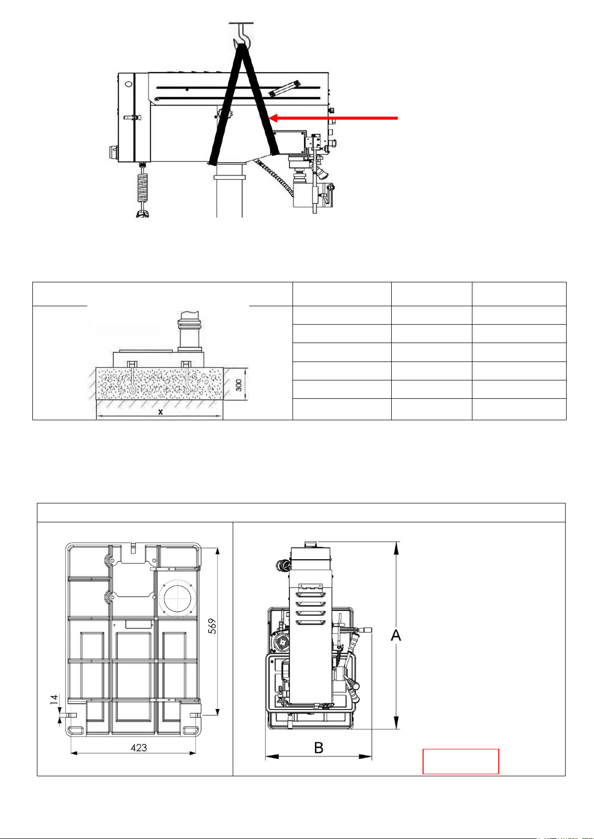
Typical lifting strap position.
1-3. Setting the machine instruction:
1. The machine base with setting hole will be set on concrete floor.
The outlined procedures of setting the machine
MODEL
AREA
SETTED SCREW
BX-834VS
X=900×700
M12
2. The dimension of setting hole:
Consider existing and anticipated needs, size of material to be processed through each machine, and
space for auxiliary stands, work tables or other machinery when establishing a location for your
machine. See Figure 01.
BX-834VS Dimensions(m/m)
BX-834VS
A=1000
B=560
Lifting Straps
Figure 01
3
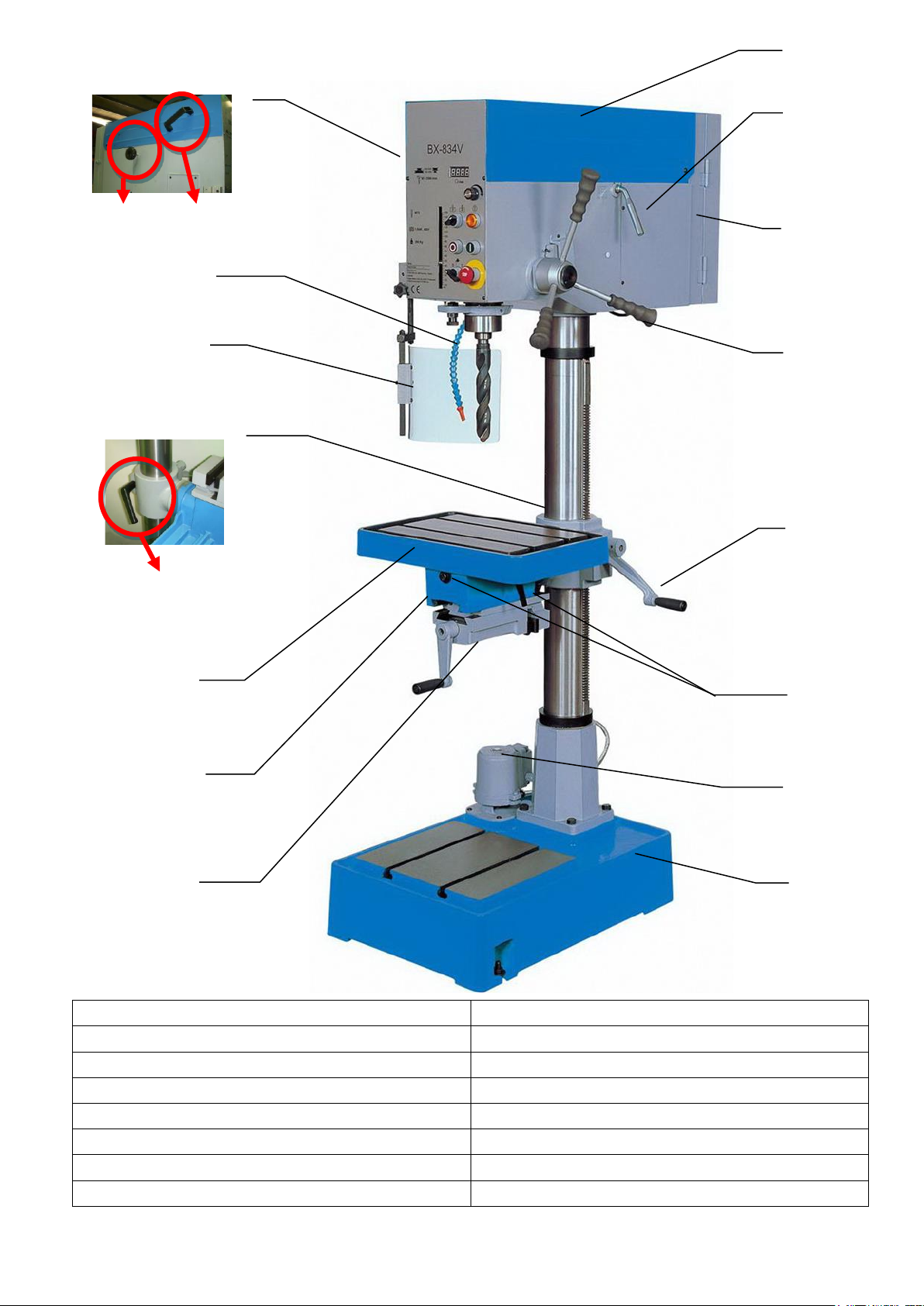
1-4. Major Parts:
A= Pulley Cover
I= Vice 4”
B= Motor Handle
J= Vice Lock
C= Switch cover
K= Table
D= Feed Handle
L= Clamp Handle
E= Table Handle
M= Safety Guard
F= Table Lock
N= Pump Valve Lock
G= Pump Motor
O=Belt Tension Lock
H= Base
P=Belt Cover Handle
O P
C D K E H M A B I
G
L
F
J
N
4
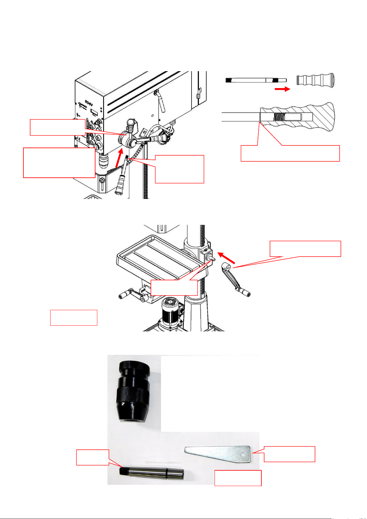
1-5. Items Needed for Set Up
1.The downfeed handles must be installed to operatethe drill press.
To install the downfeed handles:
Thread the handles into the spindle hub, as shown in Figure 02, and tighten.
2.Install the crank lever over the pinion shaft, and tighten the setscrew in the crank handle against the flat
part of the pinion shaft. Figure 03,
3. The drill chuck attaches to the spindle by means of the arbor, shown in Figure 04. Matched tapers on
the arbor and the inside of the chuck create a semipermanent assembly when properly joined.
Figure 03
Flat part
Arbor
Drill shifter
Figure 04
Hex Wrench 4mm
Figure 02
Downfeed handles
Spindle Hub
Wrench
Size 12mm
Locked to the reference line
5
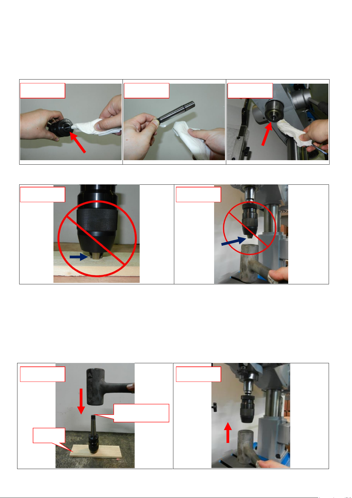
1-6. To assemble the drill chuck and mount it to the spindle:
1. Use mineral spirits to thoroughly clean the drill chuck, arbor, and spindle sockets and dry all surfaces
before assembly. Follow all safety warnings on the container of the mineral spirits. Failure to clean the
mating surfaces may cause the tapered fit to loosen during operation, resulting in separation and an
unsafe condition. Figure 05.06.07
2. Use the chuck key to adjust the jaws of the drill chuck until they are inside the drill chuck body.
Figure 08.09
3. Place the drill chuck face down on a workbench. The arbor has a short taper and a long taper. Place
the short taper into the socket in the back of the drill chuck and tap it with a rubber or wooden mallet, as
shown in Figure 10. If the chuck fails to remain secure on the arbor, repeat Steps 1 & 2.
4. Slide the arbor into the spindle socket while slowly rotating the drill chuck. The socket has a
rectangular pocket where the tang (or flat portion of the arbor shown in Figure 10) fits into.
5. Seat the chuck with a rubber mallet, as shown in Figure 11.
Figure 05
Figure 06
Figure 07
Figure 08
Figure 09
Figure 10
Figure 11
Wood
Tang-Side Up
6
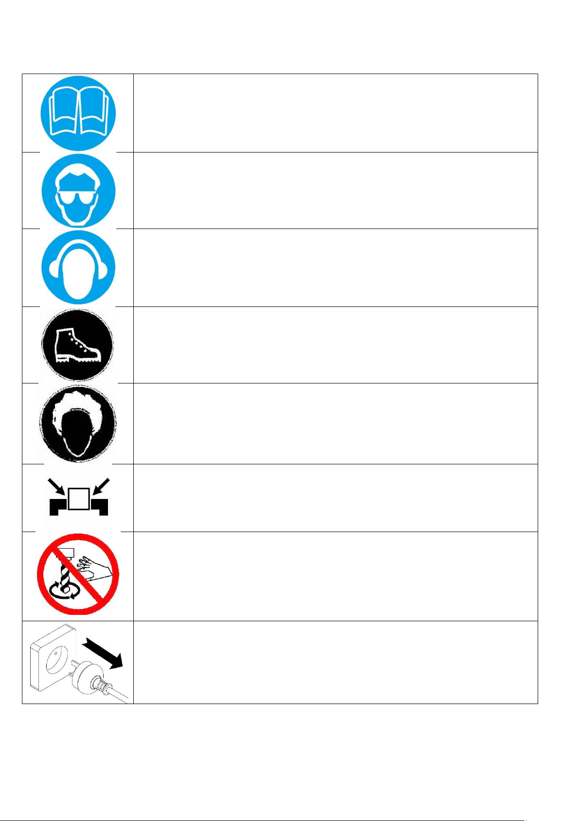
2. Safety Instruction:
Please read the safety instruction and operation instruction
carefully.
Please do wear a safety glass to avoid any material from
coming into the eyes whilst operation.
Please do wear ear mufflers or earplugs to avoid any noise
from hurting the listening whilst operation.
Please do wear proper work clothing whilst operation.
Loose clothing or tie are prohibited to avoid any
unnecessary incident.
If a operator has long hair, please do fix the hair or use cap
to avoid the hair from being drawn into it.
A processing workpiece shall be fixed firmly to avoid it
from being thrown out whilst operation.
Please keep both hands far from the rotating tool whilst
operation. Cotton gloves are prohibited to avoid from being
drawn into cutter.
Please pull out the power plug to avoid any electric shock
incident whilst product maintenance or repair.

7
Read Instruction Manual before operating the machine for your own safety.
1. Make sure the power voltage is for the machine. Before connecting the plug to socket, it is necessary
to check the power spec. to avoid any damage occurring.
2. If the machine is not used for a long time, the plug should be disconnected.
3. Never put the power cable near the fire or water environment, to break or press the power cable is
not allowed.
4. It shall be stable and securely fixed in machine installation procedure for the machine to be used
safely.
5. The working piece must be tightly fixed on table by vise or clamp.
6. Use recommended cutting liquid; consult the owner’s manual for recommendation.
7. Feed speed should be executed under safety scope, please refer to manual 3-3.
8. Wear proper apparel, no loose clothing, gloves, neckties, ring, and bracelet during operation. Always
wear safety glasses, cap and specific clothes.
9. Check all parts are in place and securely locked before transportation. Bump and crash are
prohibited.
10. Regular maintenance and repaired should be executed in accordance with the rules of manual.
11. Use the industrial suction to clean the chip is recommended.
12. Use carrier to move the working piece which the weight is more than 10 kg is recommended.
13. Wear safety gloves when install the drilling bit or tooling to avoid hurting your hand is
recommended.
14. This machine only be used following material brass, cast iron, steel, iron, aluminum .
15. It is prohibited to open the pulley cover during operation.
16. It is prohibited to use damaged or cracked parts
17. It is prohibited to remove the guard cover away during operation.
 Loading...