

Promac BX-834, BX-834V, BX-840VB Instruction Manual
BX-834 / BX-834V / BX-840VB
Instruction Manual
TOOLTEK CO.,428 Taichung ,Taiwan
Walter Meier (Tool) AG,CH-8117
Fällanden
TOOL(France)Sarl,F-91029 Evry
CAUTION: BEFORE USING THE MACHINE BE SURE TO READ THIS MANUAL

Contents of Manual:
1-1. Unpacking ----------------------------------------------------------------1
1-2. Transportation instruction ------------------------------------------1
1-3. Setting the machine instruction ----------------------------------2
1-4. Major parts----------------------------------------------------------------3
2. Safety instruction------------------------------------------------------4-5
3-1. Control panel instruction -------------------------------------------6
3-2. Operation illustration and procedure---------------------------7
3-3. Operation tips------------------------------------------------------------8-9
3-4. Spindle Feeding --------------------------------------------------------10
4. Operation procedure -------------------------------------------------11
5. Trouble - Shooting ----------------------------------------------------12
6. Maintenance-------------------------------------------------------------13
7. Specification and sound pressure------------------------------14
8. Control circuit diagram and component part list ---------15-18
9. Drawing and parts list ---------------------------------------------19-25

1-1. Unpacking:
Before unpacking, make sure the carton configuration have no damaged, broken or parts
extruded, if found above defect case, contact to your retailer for change a new one as soon as
possible.
Unpacking procedure:
1. Carefully open the carton. (Pull it from the bottom to the top)
2. Take out and read the manual, check parts list and relative ancillary.
3. Inspect the machine outline if it is in normal condition or not. Crack, rust, collapse and separated
are strictly prohibited.
4. Cleaning the surface of the machine.
5. Assembly the drill machine base on manual, instruction guide.
1-2. Transportation instruction:
1. Please refer to instruction manual in specification and machine weight to arrange handling
manner. Be sure to use capable fork – lifter or hoist to lift of machine.
2. The handling and transportation shall be carried out by qualified persons.
3. Fork – lift or hoist can be used in handling and shall be operated by qualified driver.
4. While transportation, keep attention to the balance of machine.
5. During handling, the machine shall be lifted only in vertical direction.
6. Before handling, make sure all movable parts are secured in their position and all movable
accessories should be removed from machine.
7. The steel rope should average pull the machine head, table and column tightly.
8. Keep all the process in a carefully and slightly condition.
9. Bump or crash are strictly prohibited. It will cause precision shift and electronic controller
damaged.
1
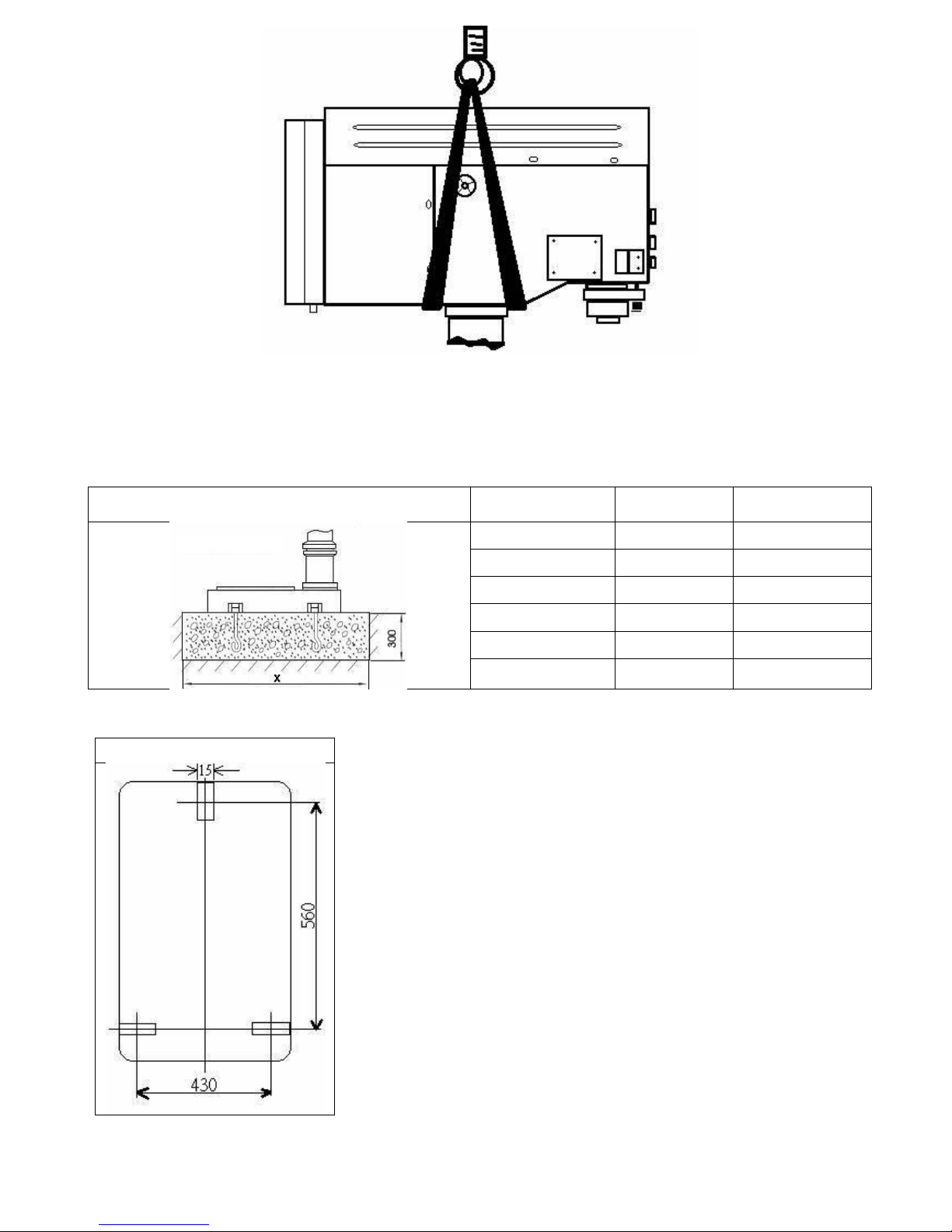
1-3. Setting the machine instruction:
1.The machine base with setting hole will be setting the machine on concrete floor.
2.Recommended the high of dimension switch operation is 1.4 -1.6 M.
The outlined procedures of setting the machine
MODEL
AREA
SETTED SCREW
BX-834
X=900×700
M12
BX-834V
X=900×700
M12
BX-840VB
X=900×700
M12
3. The dimension of setting hole:
BX-834/834V/840VB
2
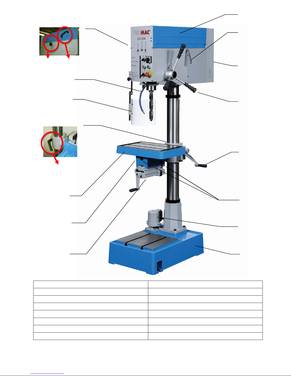
1-4. Major Parts:
A= Pulley Cover
I= Vice 3” (For BX-834V or BX-834)
B= Motor Handle
J= Vice Lock (For BX-834V or BX-834)
C= Switch cover
K= Table
D= Feed Handle
L= Clamp Handle
E= Table Handle
M= Safety Guard
F= Table Lock (For BX-834V or BX-834)
N= Pump Valve Lock
G= Pump Motor
O=Belt Tension Lock
H= Base
P=Belt Cover Handle
3
O P
C D K E H M A B I
G
L
F J N

2. Safety Instruction:
Read Instruction Manual before operating the machine for your own safety.
1.Make sure the power voltage is for the machine. Before connecting the plug to socket, it is necessary
to check the power spec. to avoid damaged occurred.
2. During the machine is not used for a long time, the plug should be disconnected.
3. Never stand the power cable near the fire or water environment, any broken or pressed of power
cable is not allowed.
4. It shall be stable and securely fixed in machine installation procedure for the machine to be used
safety.
5. The working piece must be tightly fixed on table by vise or clamp.
6. Use recommended cutting liquid, consult the owner’s manual for recommended.
7. Feed speed should be executed under safety scope, please refer to manual 3-3.
8. Wear proper apparel, no loose clothing, gloves, neckties, ring, bracelet to get caught in operation.
Always wear safety glasses, cap and specific clothes.
9. Check all parts are in place and securely locked before transportation. Bump and crash are
prohibited.
10. Routing maintenance and repaired should be executed follow the rules of manual.
11.Recommended use the industrial suction to clean the chip .
12.Recommended move the working piece which the weight over 10 kg used carrier move it.
13.Recommended wear safety gloves when install the drilling bit or tooling to avoid hurt your hand.
14.This machine only be used following material brass, cast iron, steel, iron, aluminum .
15. It is prohibited to open the pulley cover in operation.
16. It is prohibited to use damaged or cracked parts
17. It is prohibited to removed the guard cover away in operation.
4
18. It is prohibited to move the table when machine in operation.
19. It is prohibited to operate this machine beyond the limit of its capacity,
20.Refer to this instruction for details.
21. It is prohibited to insert one's hand or finger into the hole of working piece in operation.
22. It is prohibited all visitors and children should stand near work area while the machine in operation.
23. It is prohibited to wear gloves, neckties, ring, bracelet and loose clothing in operation.
24. It is prohibited to use plastic and wooden working.
25.Check again before switch on power,
A-Make sure the power voltage is for the machine.
B- Make sure the machine is completely assembled and installed
C- Make sure chuck, working table, working piece are completely secured or tightly fixed.
D- Make sure the chuck key is removed from chuck.
E- Make sure drill bit or tooling need to be fixed in the chuck.
26.Switch off power at once;
A-When fixed or removed working piece.
B-When the normal maintenance, service , adjustment or repairing.
C-When the operator leave the machine.
D-When corrected work table adjustment and depth position.
E-When change or remove the drilling bit or tooling.
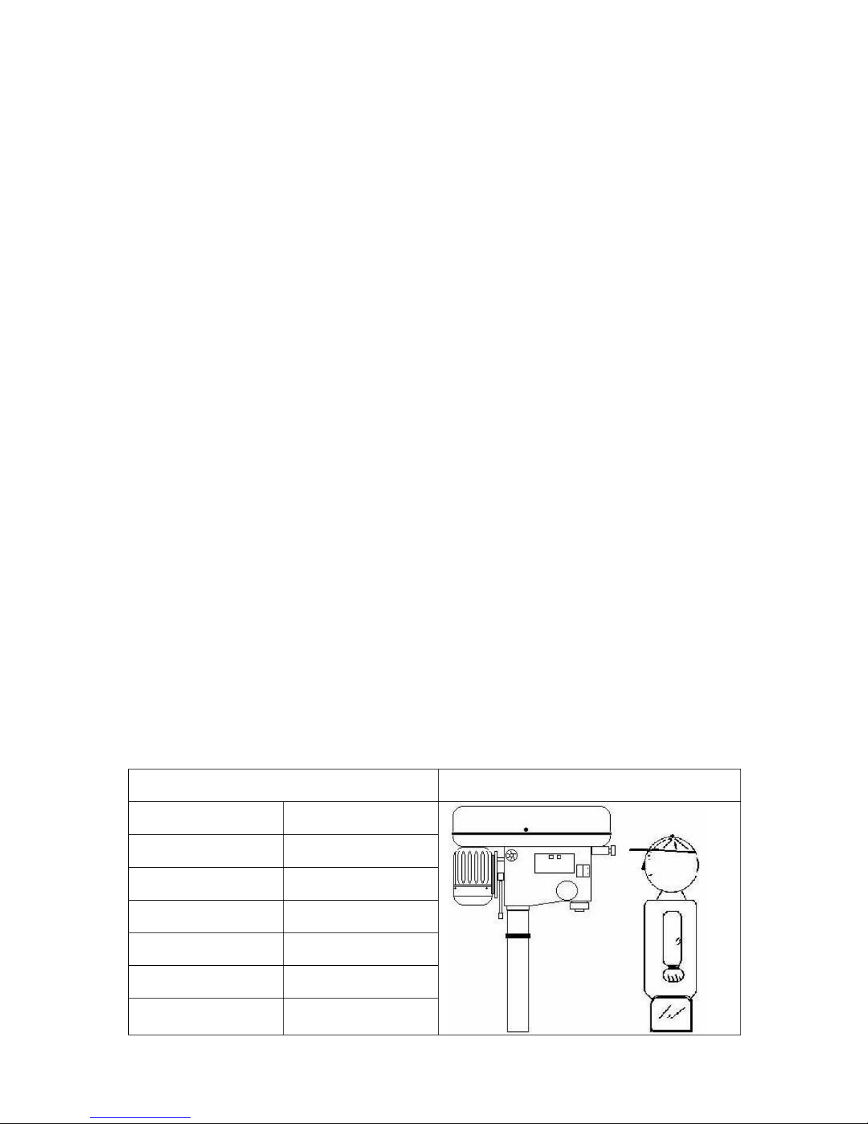
27. Working temp.5 --- 40℃,Humidity 40--- 50,Elevation 0 ---1000 M
Storage temp -25--- 55℃
28.Operate location diagram for reference.
Diagram 1
Diagram 2
MODEL
Ultimate loading
BX-834
70 kg
BX-834V
70 kg
BX-840VB
50 kg
5
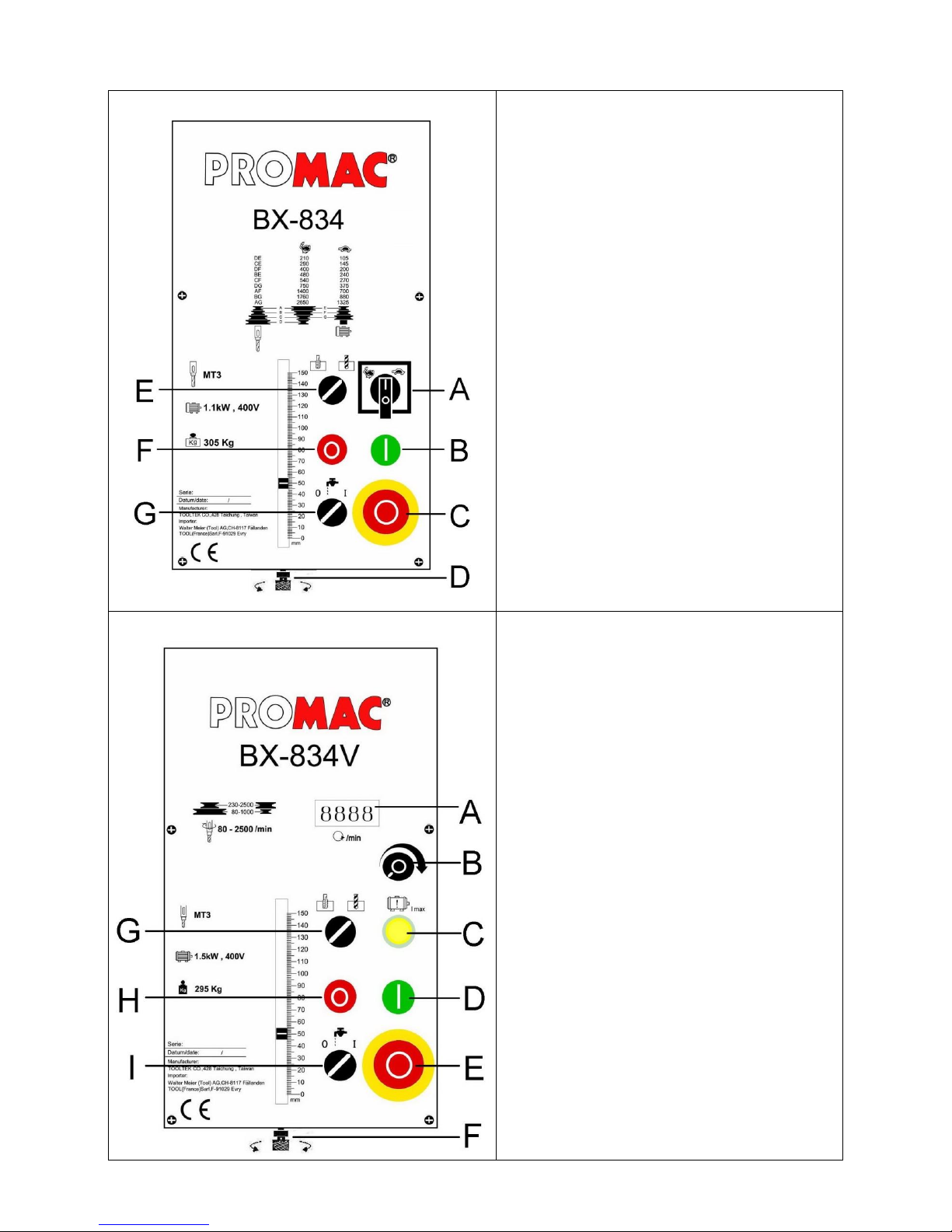
3-1. Control panel instruction:
BX-834 only
A. Jkm Cam Switch (high/low)
B. Start Button
C. Emergency Stop Button
D. Feed Depth Adjustment
E. Drill / Tap Switch
F. Stop Button
G. Cutting Liquid Control Switch
For BX-834V or BX-840VB
A. min-1 or /min (R.P.M.) Indicator
B. Speed Control Switch
C. Fault light
D. Start Button
E. Emergency Stop Button
F. Feed Depth Adjustment
G. Drill / Tap Switch
H. Stop Button
I. Cutting Liquid Control Switch
6

3-2. Operation illustration and procedure:
1. Drill / Tap switch : For changing the machine to Drill Mode or Tap Mode.
2. Work table and vise adjustment (for BX-834V / BX-834 only)
Loose the work table and vise set screw then turn the work table 180 degree, let the
vise be upside. Then completely tight the set bolt.
3. There are two T grooves in the worktable. It is used to fix the work piece.
4. There are two T grooves in the base, too. It is convenient for fixed the longer, heavier and larger
working piece.
5. Spindle speed adjustment is controlled by the speed control switch. The speed will be showed
out in the electronic digital meter. (for BX-834V/BX-840VB only)
6. The belt tension could be adjusted by a quickly crank in the right side of the machine head.
7. The pulley cover is strictly prohibited to open in normal operation condition.
8. Do not adjust the worktable when machine in operation.
9. Protect safety guard shall be allocated in a proper position in operation. It is controlled by a
micro witch.
10. If it needs to stop urgently, just push the emergency stop switch.
11. These machines have special design for tapping, a quick change device.
During tapping, if you want spindle to turn reversely and withdraw tapping tip, just pull up grip
handle only. If you want to continue to operate, just press down grip handle.
Chuck Protection Guard
7
 Loading...