

Promac 941A, 941VA Operating Instructions Manual
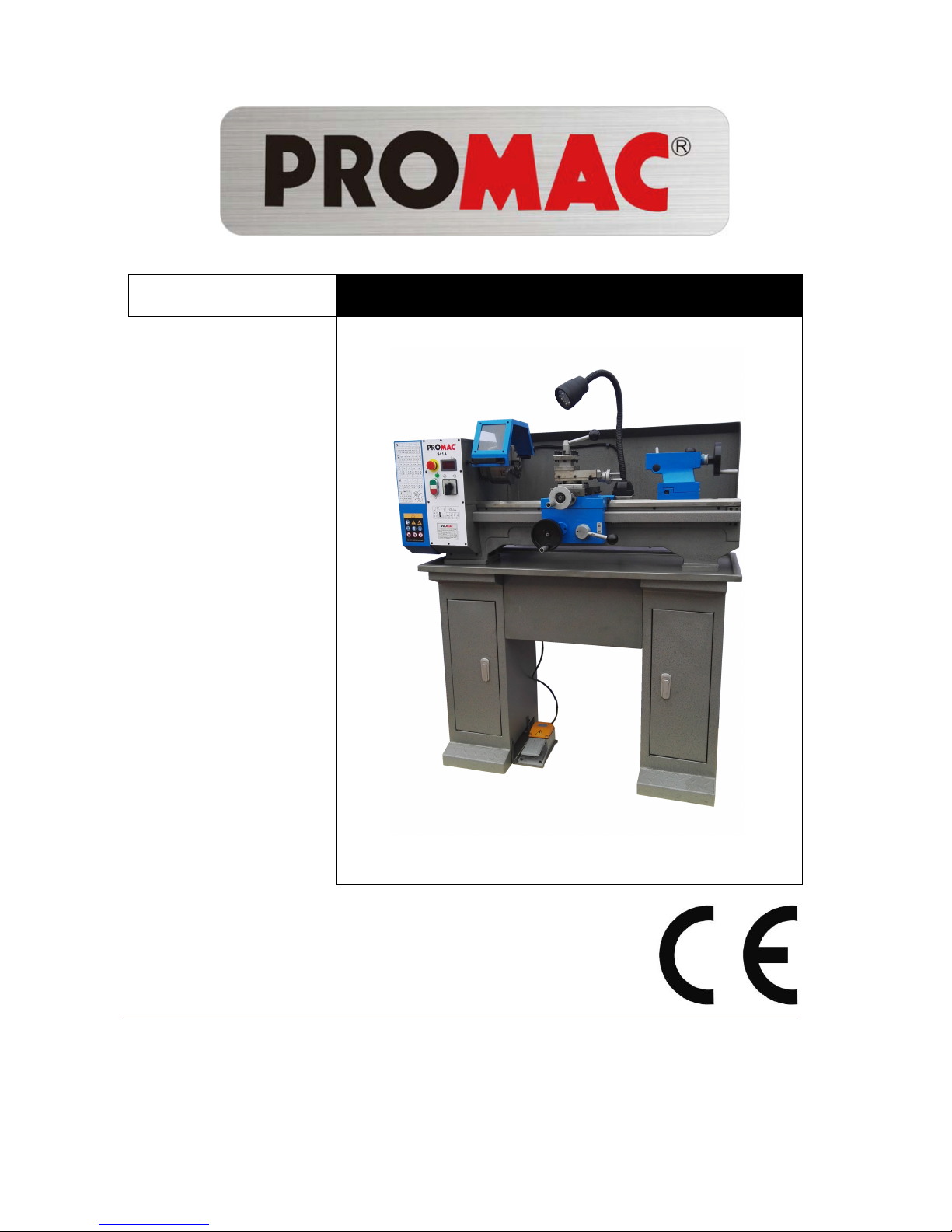
941A
METAL LATHE
Original:
G
B
O
perating Instructions
M-BD-941A-M
Schweiz / Suisse
JPW (TOOL) AG
Tämperlistrasse 5
CH-8117 Fällanden Switzerland
www.promac.ch
France
TOOL France / PROMAC
57, rue du Bois Chaland, Z.I. du Bois Chaland
case postale 2935 FR-91029 Evry Cedex
www.promac.fr
2016-05

CE‐ConformityDeclaration
CE‐Konformitätserklärung
DéclarationdeConformitéCE
Product/Produkt/Produit:
MetalLathe
Metalldrehbank
Touràmétaux
941A
Brand/Marke/Marque:
PROMAC
Manufacturer/Hersteller/Fabricant:
JPW(Tool)AG,Tämperlistrasse5,CH‐8117Fällanden
Schweiz/Suisse/Switzerland
Weherebydeclarethatthisproductcomplieswiththeregulations
Wirerklärenhiermit,dassdiesesProduktderfolgendenRichtlinieentspricht
Parlaprésente,nousdéclaronsqueceproduitcorrespondauxdirectivessuivantes
2006/42/EC
MachineryDirective
Maschinenrichtlinie
DirectiveMachines
2014/30/EU
electromagneticcompatibility
elektromagnetischeVerträglichkeit
compatibilitéélectromagnétique
designedinconsiderationofthestandards
undentspechendfolgenderzusätzlicherNormenentwickeltwurde
etétédéveloppédanslerespectdesnormescomplémentairessuivantes
ENISO12100:2010
ENISO23125:2015
EN60204‐1:2006+A1:2009
EN61000‐6‐2:2005
EN61000‐6‐4:2007+A1:2011
ResponsiblefortheDocumentation/Dokumentations‐Verantwortung/RésponsabilitédeDocumentation:
HansjörgMeier
HeadProduct‐Mgmt./LeiterProdukt‐Mgmt./Resp.GestiondesProduits
JPW(Tool)AG
2016‐05‐24AlainSchmid,GeneralManager
JPW(Tool)AG,Tämperlistrasse5,CH‐8117Fällanden
Schweiz/Suisse/Switzerland

1

Table of Contents
INTRODUCTION......................................................................................................................4
MAIN PARAMETERS……………………………………………………………………......5
SECTION 1: SAFETY...............................................................................................................7
SECTION 2: POWER SUPPLY...............................................................................................9
Availability………………………………………………………………………9
Circuit Requirements…………………………………………………………..9
Grounding & Plug Requirements…………………………………………….10
Extension Cords……………………………………………………………….10
SECTION 3: SETUP……………………………………………………………………...…11
Unpacking……………………………………………………………………...11
Inventory………………………………………………………………………11
Clean Up……………………………………………………………………….12
Installation Dimensions……………………………………………………….12
Check Gearbox Oil……………………………………………………………12
Open the Cover………………………………………………………………..13
Install belt and Chang speeds………………………………………………...13
Test Run Lathe………………………………………………………………...14
SECTION 4: OPERATE……………………………………………………………………..15
General…………………………………………………………………………15
Controls…………………………………………………………...……………15
Removing/Installing Chuck or Faceplate…………………………………...16
Dead Centers…………………………………………………………………..17
Tailstock Positioning…………………………………………………………..18
Changing Tool Posts…………………………………………………………..18
Cross Slide…………………………………………………………………......18
Compound Slide……………………………………………………………….19
Carriage Handwheel…………………………………………………………..20
Half Nut Lever…………………………………………………………………20
Carriage/Cross Feed Lever…………………………………………...………20
Carriage Lock………………………………………………………………….20
Gearbox Levers………………………………...……………………………...20
Threads and Change gears……………………………………………………21
Left threads and reverse cutting feed………………………………………...21
Clutch Overload…………………………………………………...…………..22
SECTION 6: MAINTENANCE……………………………………………………….……..23
Lubrication…………………………………………………………………….23
Ball oilers............................................................................................................23
Feed Rate Gearbox Oil Reservoir....................................................................24
Gibs…………………………………………………………………………….25
Bearing Preload……………………………………………………………….26
2
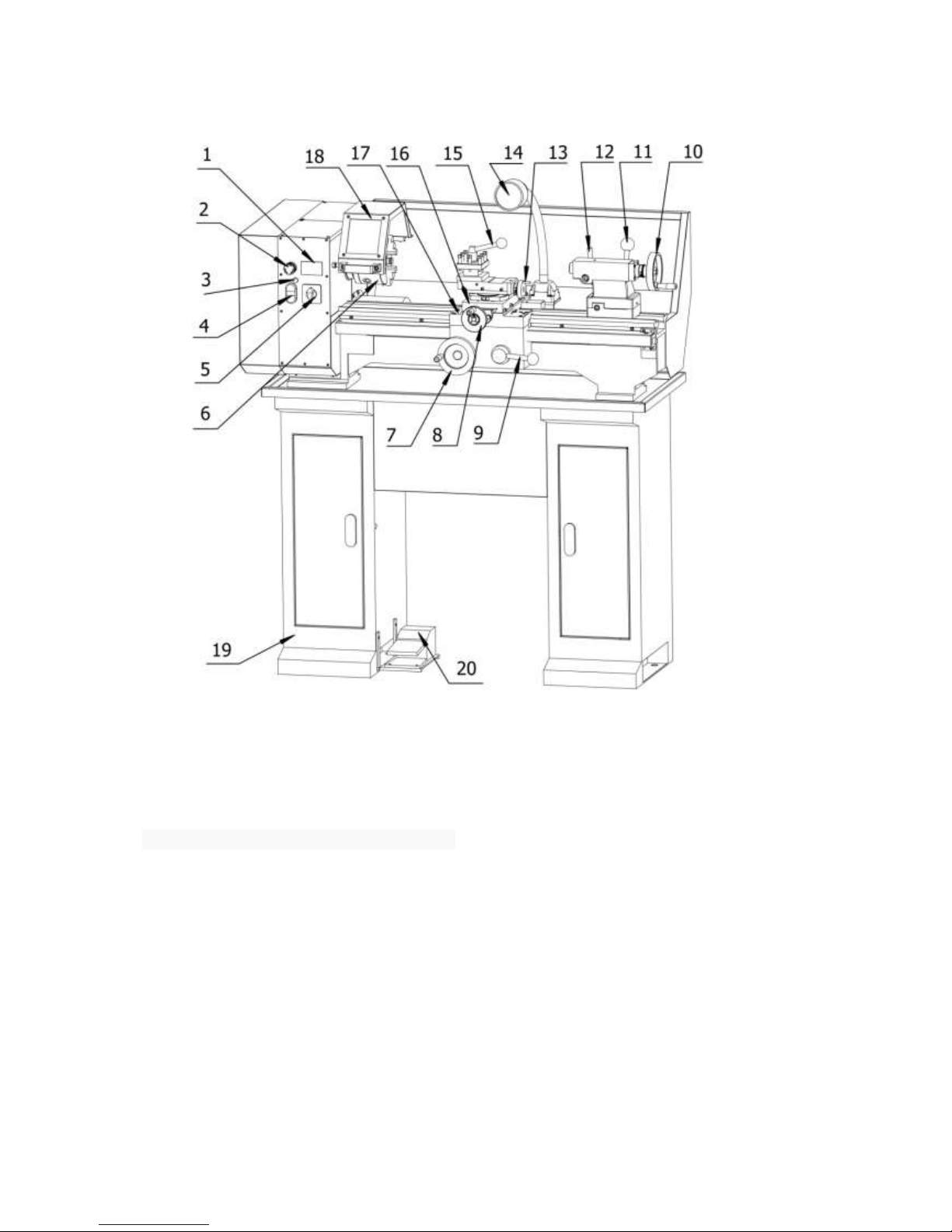
IDENTIFICATION
The following is a list of controls and components on the lathe. Please take time to become
familiar with each term and its location. These terms will be used throughout the manual
and knowing them is essential to understanding the instructions and terminology used in
this manual.
1. Speed of Spindle(rpm)
2. Emergency Stop Switch
3. Lathe Power Indicator Light
4. Lathe ON/OFF switch
5. Lathe Forward/Reverse Switch
6. Lathe Chuck
7. Carriage Handwheel
8. Cross Slide Handwheel
9. Half Nut Lever
10. Tailstock Barrel Handwheel
11. Tailstock Clamp Bolt
12. Tailstock Center Lock
13. Compound Slide Handwheel
14. Work Light
15. Tool Post
16. Cross Slide
17. Carriage
18. Headstock Eyeshield
19. Work Table
20. Foot Switch
3

Model 941A Main Parameters
Product Dimensions:
Weight..................................................................................................................................180kg
Width (side-to-side) x Depth (front-to-back) x Height.....................................114 x 60 x 120 cm
Shipping Dimensions:
Type.............................................................................................................................Wood Crate
Content..............................................................................................................................Machine
Weight.............................................................................................................................. 225 kg.
Length x Width x Height..................................................................................123 x 73 x 140.cm
Electrical:
Minimum Circuit Size.........................................................................................................10 amp
Switch..................................................................................................................Forward/Reverse
Motors: Main
Type........................................................................................................................... …..YL7134
Outpower...................................................................................................................... …..550W
Amps......................................................................................................................4.2 amp (230V)
Speed............................................................................................................... 1400 RPM (50Hz)
Speeds.......................................................................................................................................... 1
Power Transfer .................................................................................................Belt Drive to Gear
Bearings..............................................................................Shielded and Permanently Lubricated
Main Specifications:
Operation Info
Swing Over Bed................................................................................................................250 mm
Distance Between Centers................................................................................................555 mm
Swing Over Cross Slide.....................................................................................................150 mm
Swing Over Saddle............................................................................................................210 mm
Compound Travel............................................................................................................... 70 mm
Carriage Travel..................................................................................................................565 mm
Cross Slide Travel..............................................................................................................100 mm
Max. Turning Tool Size................................................................................................10 x 10mm
Headstock Info
Spindle Bore.................................................................................................................... Φ20 mm
Spindle Size................................................................................................................ Φ52x11mm
Spindle Taper..................................................................................................................... MT#3
Number of Spindle Speeds..........................................................................................................6
Spindle Speeds......................................................(50Hz) 125, 210, 420,620, 1000, 2000 rpm
Spindle Bearings...........................................................................Tapered Roller + Ball Bearing
4

Tailstock Info
Tailstock Taper.....................................................................................................................MT#2
Tailstock Barrel Diameter...............................................................................................Φ30 mm
Tailstock Barrel Travel........................................................................................................50mm
Threading Info of Metric Lathe
Number of Longitudinal Feeds...................................................................................................2
Range of Longitudinal Feeds............................................................................0.1 or 0.2 mm/rpm
Number of Inch Threads.............................................................................................................. 6
Range of Inch Threads..................................................................................................10 - 44 TPI
Number of Metric Threads..........................................................................................................15
Range of Metric Threads...............................................................................................0.4 - 3 mm
Dimensions
Bed Width..........................................................................................................................135 mm.
Lead screw Diameter............................................................................................................20mm
Lead screw Pitch....................................................................................................................2 mm
Lead screw Length.............................................................................................................792 mm.
Steady Rest Capacity.....................................................................................................6 – 40 mm
Follow Rest Capacity.....................................................................................................6 – 40 mm
Faceplate Size................................................................................................................Φ220 mm.
Floor to Center Height.......................................................................................................335 mm
Construction
Headstock........................................................................................................................ Cast Iron
Headstock Gears.....................................................................................................................Steel
Bed..................................................................................................Induction Hardened Cast Iron
Body.................................................................................................................................Cast Iron
Paint..................................................................................................................................... Epoxy
5

SECTION 1: SAFETY
READ MANUAL BEFORE OPERATING MACHINE.
FAILURE TO FOLLOW INSTRUCTIONS BELOW WILL
RESULT IN PERSONAL INJURY.
Standard Safety Instructions
1. Thoroughly read the Instruction Manual before operating your machine.
Learn the applications, limitations and potential hazards of this machine. Keep
the manual in a safe and convenient place for future reference.
2. Keep work area clean and well lighted. Clutter and inadequate lighting invite
potential hazards.
3. Ground all tools. If a machine is equipped with a three-prong plug, it must be
plugged into a three-hole grounded electrical receptacle or grounded extension
cord. If using an adapter to aid in accommodating a two-hole receptacle, ground
using a screw to a known ground.
4. Wear eye protection at all times. Use safety glasses with side shields or
safety goggles that meet the appropriate standards of the American National
Standards Institute (ANSI).
5. Avoid dangerous environments. Do not operate this machine in wet or open
flame environments. Airborne dust particles could cause an explosion and severe
fire hazard.
6. Ensure all guards are securely in place and in working condition.
7. Make sure switch is in the OFF position before connecting power to
machine.
8. Keep work area clean, free of clutter, grease, etc.
9. Keep children and visitors away. Visitors must be kept at a safe distance
while operating unit.
10. Childproof your workshop with padlocks, master switches or by removing
starter keys.
11. Stop and disconnect the machine when cleaning, adjusting or servicing.
6

12. Do not force tool. The machine will do a safer and better job at the rate for
which it was designed.
13. Use correct tool. Do not force machine or attachment to do a job for which it
was not designed.
14. Wear proper apparel. Do not wear loose clothing, neck ties, gloves, jewelry,
and secure long hair away from moving parts.
15. Remove adjusting keys, rags, and tools. Before turning the machine on,
make it a habit to check that all adjusting keys and wrenches have been removed.
16. Avoid using an extension cord. But if you must use one, examine the
extension cord to ensure it is in good condition. Immediately replace a damaged
extension cord. Always use an extension cord that uses a ground pin and
connected ground wire. Use an extension cord that meets the amp rating on the
motor nameplate. If the motor is dual voltage, be sure to use the amp rating for
the voltage you will be using. If you use an extension cord with an undersized
gauge or one that is too long, excessive heat will be generated within the circuit,
increasing the chance of a fire or damage to the circuit.
17. Keep proper footing and balance at all times.
18. Lock your mobile base, if used, to prevent the machine from moving
during operation.
19. Do not leave machine unattended. Wait until it comes to a complete stop
before leaving the area.
20. Perform machine maintenance and care. Follow lubrication and accessory
attachment instructions in the manual.
21. If at any time you are experiencing difficulties performing the intended
operation, stop using the machine! Then contact our technical support or ask a
qualified expert how the operation should be performed.
22. Habits—good and bad—are hard to break. Develop good habits in your
shop and safety will become second-nature to you.
23. Be aware that certain metal shavings and cutting fluids may cause an
allergic reaction in people and animals, especially when cutting fumes can be
inhaled. Make sure you know what type of metal and cutting fluid you will be
exposed to and how to avoid contamination.
7
 Loading...