

Promac 213A User Manual
Drill Press
Säulenbohrmaschinen
Perceuses à colonne
213A
Switzerland France
JPW (TOOL) AG TOOL France / PROMAC
Tämperlistrasse 5 57, rue du Bois Chaland, Z.I. du Bois Chalan
CH-8117 Fällanden Switzerland case postale 2935 FR-91029 Evry Cedex
www.promac.ch www.promac.fr
05-2016

CE-Conformity Declaration
CE-Konformitätserklärung
Déclaration de Conformité CE
Product / Produkt / Produit:
Drill Press
Säulenbohrmaschine
Perceuse à colonne
213A
Brand / Marke / Marque:
PROMAC
Manufacturer / Hersteller / Fabricant:
JPW (Tool) AG, Tämperlistrasse 5, CH-8117 Fällanden
Schweiz / Suisse / Switzerland
We hereby declare that this product complies with the regulations
Wir erklären hiermit, dass dieses Produkt der folgenden Richtlinie entspricht
Par la présente, nous déclarons que ce produit correspond aux directives suivantes
2006/42/EC
Machinery Directive
Maschinenrichtlinie
Directive Machines
2014/30/EU
electromagnetic compatibility
elektromagnetische Verträglichkeit
compatibilité électromagnétique
designed in consideration of the standards
und entspechend folgender zusätzlicher Normen entwickelt wurde
et été développé dans le respect des normes complémentaires suivantes
EN ISO 12100:2010
EN 12717:2001+A1:2009
EN 60204-1:2006+A1:2009
EN 61000-6-2:2005
EN 61000-6-4:2007+A1:2011
Responsible for the Documentation / Dokumentations-Verantwortung / Résponsabilité de Documentation:
Hansjörg Meier
Head Product-Mgmt. / Leiter Produkt-Mgmt. / Resp. Gestion des Produits
JPW (Tool) AG
2016-05-24 Alain Schmid, General Manager
JPW (Tool) AG, Tämperlistrasse 5, CH-8117 Fällanden
Schweiz / Suisse / Switzerland

GB - ENGLISH
Operating Instructions
NOTE:
It is advisable for user to read this
Instruction Manual in order to avoid
accident. If the operation method used in
this drilling machine us the same as the
method used in ordinary machine,
possible hazard may occur during the
process. Therefore, it is imperative that
user should pay extra caution and make
sure that his operating method is correct.
Slight negligence to any of the safety
measures will certainly cause accident to
the user.
The manufacturer designed this machine
especially focusing on its scheduled using
scope. Therefore, it is advisable that the
user should pay attention not to exceed
the said using scope. Also, do not make
any modification to the spare parts and
structure of the machine.
If you have any question regarding and
operating method of this machine and
Cannot find the solution in the Instruction
Manual, please contact your vendor
directly.
Correct Operation Instruction of This
Machine
1 For your own safety, do not start the
said machine before reading the
Instruction Manual carefully. One of
the necessary safety measures is to
understand its operation principle and
operation method first.
2. Do not alter any of the protective
pieces in order to maintain its
completeness
3. Plug the fan plug for power supply into
the socket with earth wire. If your
socket dose not have an earth wire,
then connect the earth terminal of this
machine.
4. Before starting this machine, it is
imperative to take away all wrenches
and latch handle not connected to the
machine. Also, your should make it a
habit to check the surrounding of the
said machine every time before suing,
to see there is any small spare part
around that may cause running fault
( breakdown).
5. Before installing the machine, clean
your working ground on order to
prevent any accident occurring.
6. Do not use this machine in a highly
dangerous place. Also, do not install
the machine in a humid or water
leaking place. During the process of
work, the user should make sure to
keep its working ground clean anytime.
7. Do not let any unauthorized or
ignorant person or children near the
said machine, and should be sure to
keep a proper distance from the
machine anytime.
8. Put a safety lock on the door of your
working ground in order to prevent
children from starting the machine.
9. Avoid overloading the machine. Also,
for your own safety, be sure to abide to
its using scopes.
3/50

10. Do not use the machine outside its
using scope.
11. Wear proper clothes while working.
Do not wear any clothes that can
easily be ripped by the machine while
operating, such as clothes that flutter,
ordinary gloves scarf, ring, and small
chain. You should also wear anti-skid
shoes and hat (cap) that can fully hold
in long hairs.
12. When operating this machine, you
should wear a goggle and dust-proof
mask anytime. Besides, make sure to
abide to the related safety measures
specified by the government's Bureau
of Works.
13. Use a hand vice or other fixing device
to fix all the spare parts for processing.
Do not use your hands to fix them in
order to avoid serious accident and
unable to operate the said machine.
14. Stand firmly in front of this machine
while working (both feet's position,
body equilibrium, etc.)
15. Keep the machine and its pointed
edges clean at all time in order to get
the best working efficiency. Also,
should follow the instructions in the
Instruction Manual carefully in
changing the tools, coating grease,
and cleaning.
16. Before cleaning this machine or
changing the tools (such as saw blade,
drill), pull off the power plug first to
avoid electrocution.
17. Use the tools suggested by the
manufacturer of this machine while
working and abide to the related
instruction in the Instruction Manual,
because using spare parts not related
to this machine is an unsafe behavior.
18. Avoid touching the machine
unintentionally. Also, before plugging
in the plug into the socket, check if
switch button is as [OFF] position or
not.
19. Do not stand on the machine in order
to avoid slipping down carelessly or
hitting the blade and cause injury.
20 Remember to check abnormal part in
the running process of the machine
carefully.
It is advisable that you should change
the said part or protective piece
before continuing the work.
21 Do not leave the working ground
while the machine is running. It is
necessary for your to leave, turn off
the power and wait for the machine
to stop completely before leaving.
22 Do not use this machine if you had
taken any alcohol (liquor or wine),
medicine, or drugs.
4/50
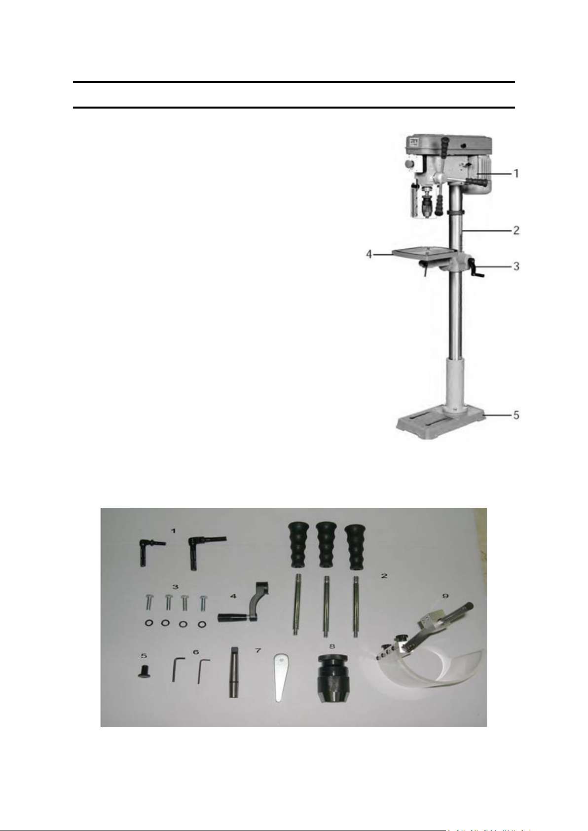
I PARTS 213A
Unpack carton, check your machine to see parts listed below:
A. Main Parts:
1 Head assembly 1 pc.
2. Column with flange 1 pc.
3. Arm of table and bracket 1 sets.
4. Table 1 pc.
5. Base 1 pc.
B. Accessories
1 Clamp bolt, table bracket 1 pc
2. Feeding handle and knobs 3 pcs
3. Screw and washer 1 set
4. Heigth adjusting handle, table bracket 1 set
5. Knob, upper pulley cover 1 pc
6. Allen wrenches (3mm, 5mm) 1 set
7. Arbor and wedge 1 set
8. Chuck 1 pc
9. Chuck guard 1 pc
Note: If you find and parts missing or damaged, contact thr dealer for exchange or
replacement
5/50

6/50
Motor and Specification:
Motor
1/2HP 230V 4 P 1420RPM, 8 A 1PH 50Hz
Drills to Center of Circle
340 mm
Drilling Capacity Mild Steel
16 mm
Distance Column to Spindle
170 mm
Number of Spindle Speeds
12
Range of Spindle Speeds (RPM)
260-2900
Column Diameter
73 mm
Spindle Taper
MT-2
Spindle Travel
80 mm
Spindle Distance to Base
1235 mm
Spindle Distance to Table (Max.)
725 mm
Table Size (L x W)
235 * 235 mm
Base Dimensions
458 * 265 mm
Machine Overall Dimension
(W x D x H)
L600 x W340 x H1570 mm
Packing Dimension (L x W x H)
L1380 x W470 x H250 mm
Net Weight
58 kg
Gross Weight
61 kg
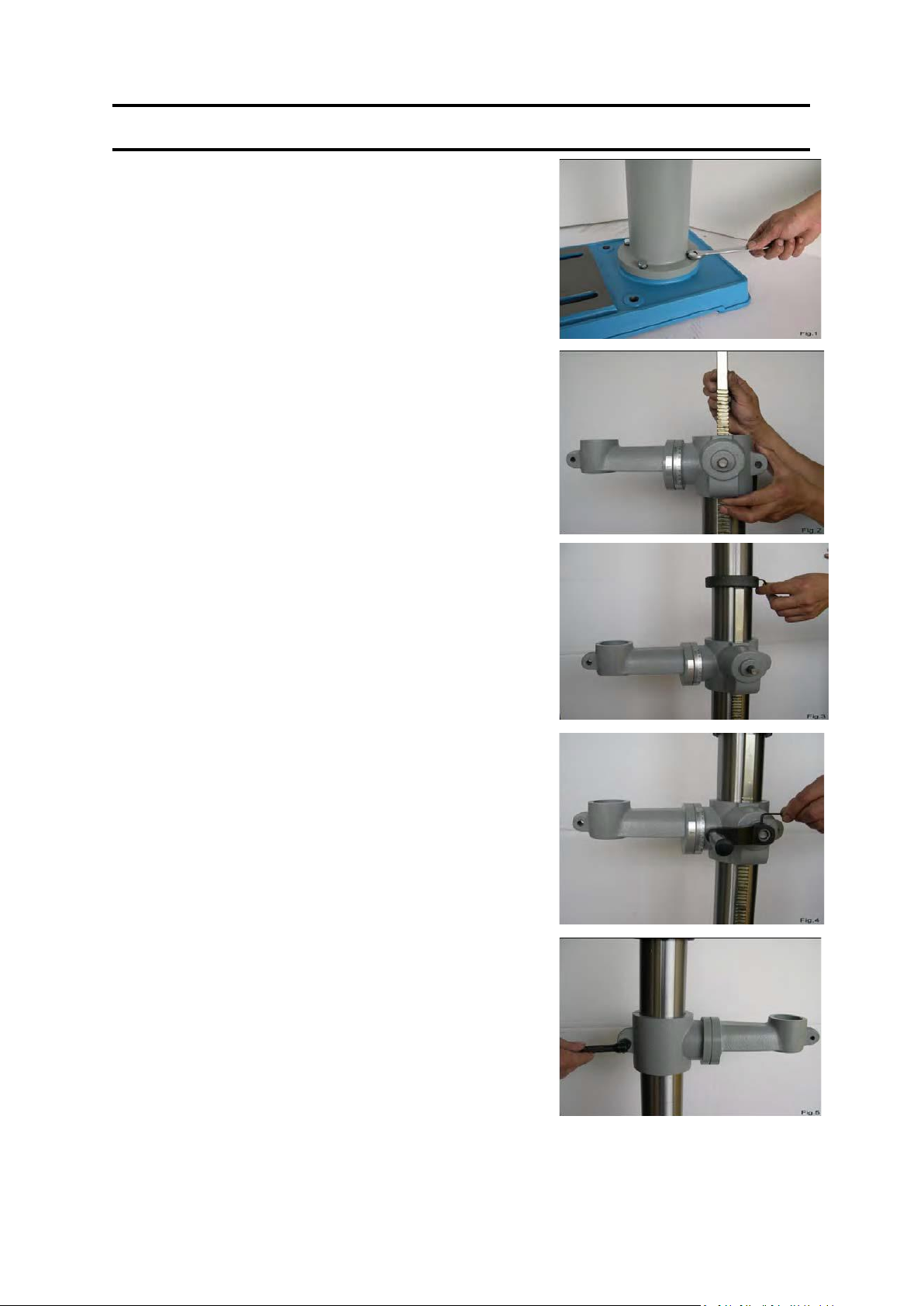
II PARTS 213A
1. Assembly the Column
* Place column assembly on base and align holes in
column support with holes in base.
* Secure the column with four or three bolts and
washers provided.
2. Install table bracket
2-1 Take off collar and rack
2-2 Install table bracket together with rack. Fig. 2.
2-3 Install collar and fix it firmly. Fig.3.
3. Install bracket handle and clamp bolt. Fig. 4, 5.
Fix handle with attached set screw.
Install clamp bolt to fix table bracket.
7/50
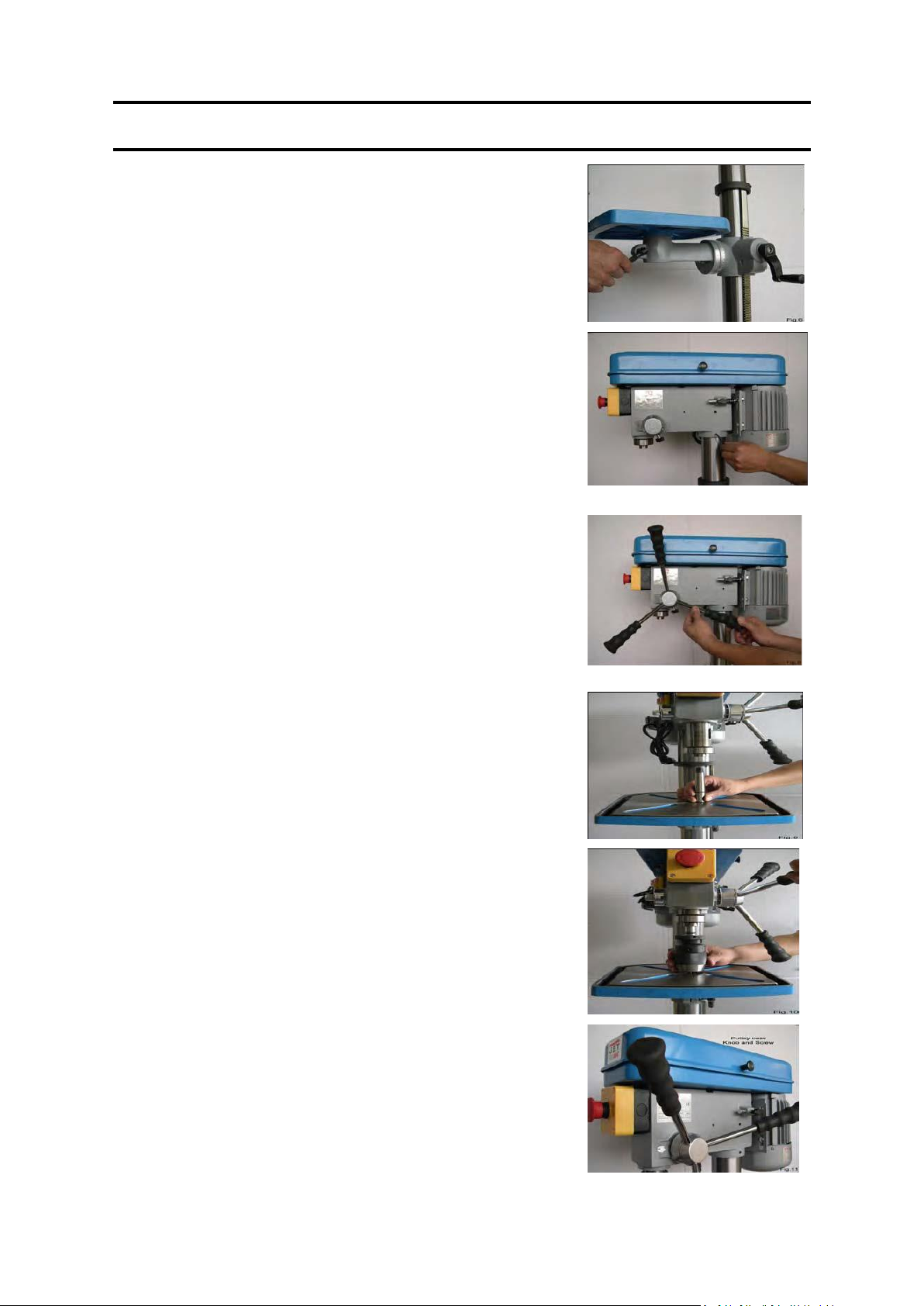
II PARTS 213A
4. Install table and clamp with bolt. Fig. 6
5. Attach the Head Assembly
* Carefully put the head assembly over column and
slide it onto column into position. Align head frame
with table and base.
* Fix set screws in right side of head to lock head into
position then tighten with Allen wrench. Fig. 7
6. Install the Feeding Handles.
* Screw knob on each feeding handle, install them into
hub of pinion shaft. Fig. 8
7. Attach the Arbor and Chuck
7-1 Insert abor into spindle first. Pull feeding handle
down to press abor inward. Fig.9
7-2 Open chuck jaws completely by turning attached
chuck key counter clockwise to the end. Put a piece
of scrap wood on the table to protect chuck nose.
7-3 Install chuck to the arbor tightly. Fig.10
8. Install knob and screw of upper pulley cover. Fig.11
8/50
III PARTS 213A
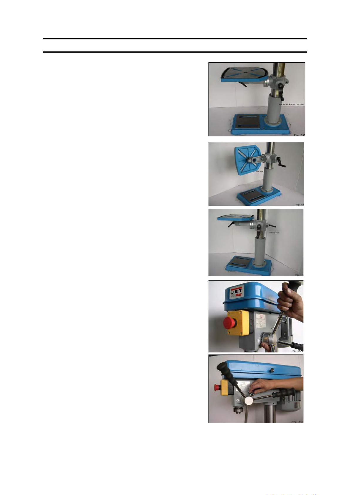
1. Table Adjustment
A. Height Adjustment
To adjust up or down, loosen the clamp bolt
then adjust the table to your desired position
by swing the table bracket handle. Fig. 12
B. Tilting Adjustment:
Loosen the table bevel lock bolt with
adjustable wrench.
Tilt table to desired angle and retighten the
bolt. Fig. 13
C. Swing 360 °
Loosen clamp bolt then swing table to
appropriate position and retighten clamp
bolt. Fig. 14
2. Feed Depth Adjustment
2-1 Depth control scale sleeve type Loose
the clamp bolt and move to the
desired depth then retighten the
clamp bolt. Fig. 15-1, 15-2
9/50
III PARTS 213A
Size
Diameter
Cast steel
Tool steel
Cast iron
Mild steel
Alum. & copper
Cutting speed
m/min
ft/min
m/min
ft/min
m/min
ft/min
m/min
ft/min
m/min
ft/min
12
40
18
60
24
80
30
100
60
200
mm
inch
Cutting speed revolution per minute
2
1/16
1910
2445
2865
3665
3820
4890
4775
6110
6550
12225
3
1/18
1275
1220
1910
1835
2545
2445
3185
3055
6365
6110
5
3/16
765
815
1145
1220
530
1630
1910
2035
3820
4075
6
1/4
610
610
955
915
1275
1220
1590
1530
3180
3055
8
5/16
480
490
715
735
955
980
1195
1220
2390
2445
10
3/8
380
405
570
610
765
815
955
1020
1910
2035
11
7/16
350
350
520
525
700
700
870
875
1740
1745
13
1/2
300
305
440
460
590
610
735
765
1470
1530
16
5/8
240
245
360
365
480
490
600
610
1200
1220
19
3/4
190
205
285
305
380
405
480
510
955
1020
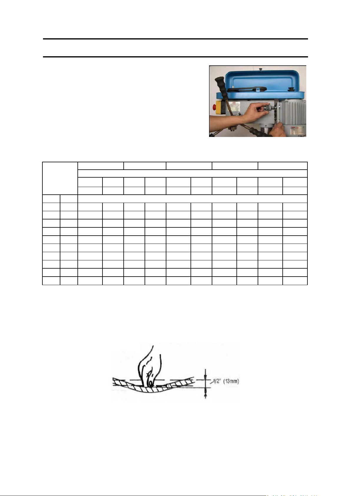
3. Speed Adjustment
3-1 1. Open the pulley case and 1 the belt tension
lock handle.
2. Choose speed for drilling operation and move
belt to correct position for desired speed.
3. Push motor backward until moderate belt
tension is acquired. Then retighten the lock
handle again. Fig. 16
The proper drill speed for a given drill bit size is as on following table:
4. Belt Tension Adjustment
For proper belt tension: Use 10 lbs pressure or hand pressure on the belt as shown
below. The distance is 1/2" (12mm)+10%
10/50
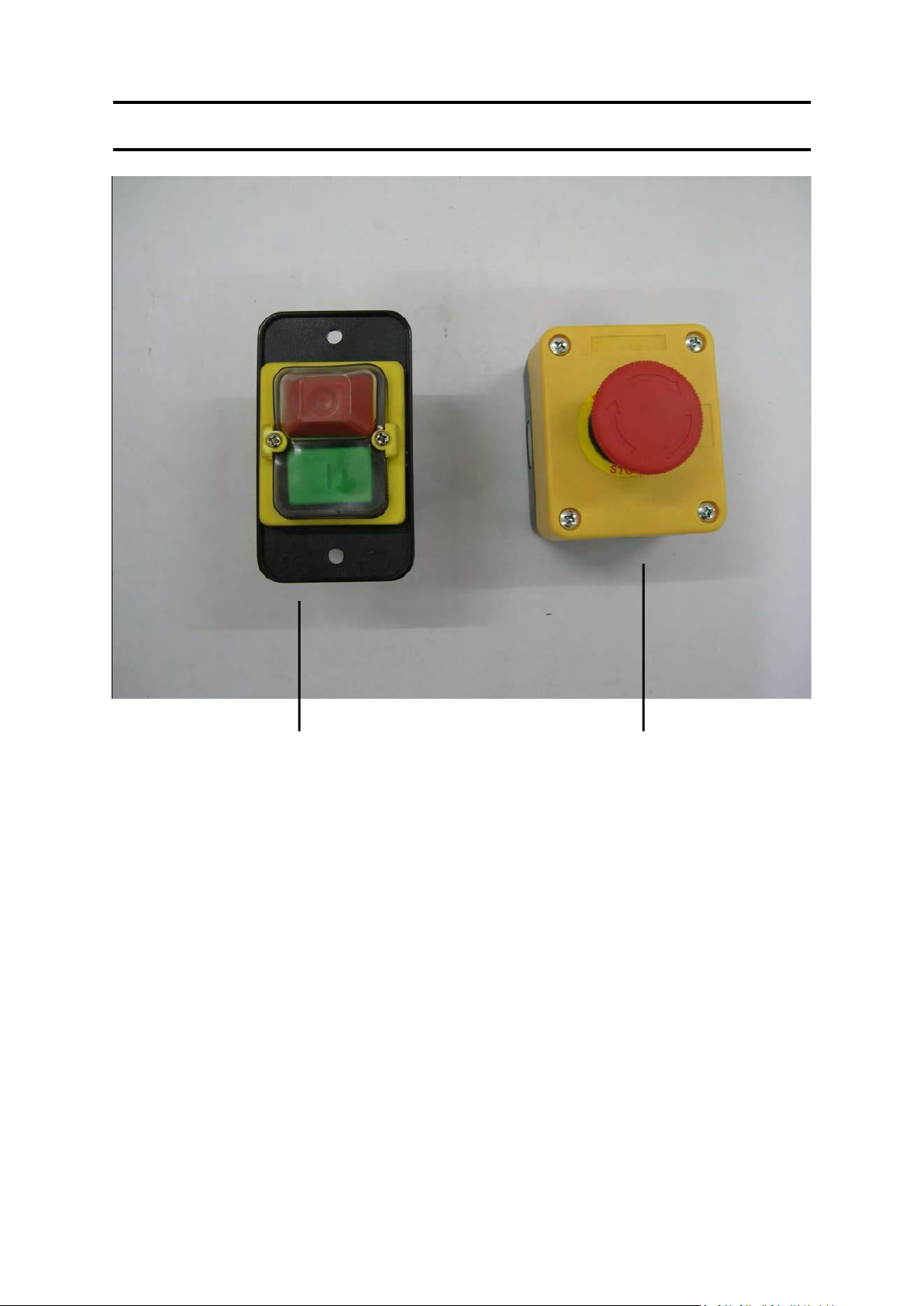
FACEPLATE AND OPERATION PANEL 213A
MAIN SWITCH
(I/O)
EMERGENCY ENCY SWITCH
11/50

Special Safety Rules For Drill Press:
1. Caution : This drill press is intended
for use only with drill bits. This use of
other accessories may be hazardous.
2. Correct drilling speeds : Factors which
determine the best speed to use in
any drill press operation are :
Kind of material being worked, size of
hold, type of drill or other cutter, and
quality of cut desired.
The smaller the drill, the greater the
required RPM. In soft materials, the
speed should be higher than for hard
metals.
3. Drilling in metal: Use clamps to hold
the work when frilling in metal. The
work should never be held in there
bare hand, the flutes of the drill may
seize the work at any time, especially
when breaking through the stock. If
the piece is whirled out of the
operator's hand, he may be injured,
in any case, the drill will be broken
when the work strikes the column.
4. The work must be clamped firmly
while drilling: Any tilting, twisting, or
shifting results not only in a rough
hole, but also increases drill breakage.
For flat work, lay the piece on a
wooden base and clamp it firmly
down against the table to prevent it
from turning. If the piece is of
irregular shape and cannot be laid flat
in the table, it should be securely
blocked and clamped.
5. The chuck shall be securely fastened
to the spindle and so that it can't
separate from spindle.
6. Remove Key from chuck after
adjustment.
7. The tool is to be disconnected from
the power supply while the motor is
being mounted, connected or
reconnected.
8. Secure the tool to the supporting
structure if, during normal operation,
there is any tendency for the tool to
tip over, slide, or walk on the
supporting surface.
9. The set screws of head frame should
be screwed tightly before suing this
machine.
10. Connect to a supply circuit protected
by a circuit breaker or time delay fuse.
11. Fasten base to floor or worktable
before using the drill press.
VII. Important Notice For CE
Handling of Machine
1. The total weight of this machine
must be ensured before handling.
2. It is better to handle this machine
with the help of lifting tools.
Environment Requirements for
Installation
1. Be sure to provide sufficient light for
operation according to the codes or
regulations published for local area.
If you do not get the information
about lighting, a light intensity of 300
Lux is the least value to be supplied.
12/50

2. The place where machine install
must be flat and big enough for the
operation.
VII Electric
ELECTRICAL CONNECTION/DISCONNECTION & OPERATION
Noise Level
1. The noise level of this machine is
about 75 db(A)during operation.
2. While taking provisions for the risk of
noise, the noise level of working
environment should be taken into
consideration also.
For three phase :
1. Electrical connection:
1. A cable with four wires is equipped
to connect your machine into the 3
phase power supply.
Please connect your machine into
the power supply with handoperated disconnecting device,
which is in compliance with
subclause 5.3 of EN 60204-1, such as
on fuse breaker or plug/socket
combination.
2. For the protection of control device,
we recommend the operation to
supply a fuse with 6 A current
rating of fuse, and the total length
between fuse and connection
terminal shall not exceed 1.5m.
3.The exact power source voltage,
frequency, and number of
phase shall be checked according to
the installation diagram and circuit
diagram.
4. The correct direction of drilling
press should be checked after
connecting.
2. Electrical disconnection:
1. The disconnection is carried out by
hand-operated disconnection device.
2. Be sure to disconnect this machining
from power source, when you want
to stop the job, Maintenance, and
adjustment.
3. Grounding
The grounding of the drilling press is
carried out by connecting the
Yellow/Green terminal of supply
cable to the grounding terminal of
power source. Be sure to ground your
machine before connecting machine to
power source in any situation.
13/50

WARNING !
Do not disconnect grounding
terminal before disconnecting
power source.
For single phase :
1. The connect, disconnection, and
grounding is carried out through the
plug, equipped on the drilling press.
For the safety reason, Do not change
this plug into any the other type
in any situation.
2. For the protection of control device, we
recommend the operated to supply a
fuse with 8 A current rating of
fuse, and the total length between
fuse and connection terminal shall not
exceed 1.5m.
3. The exact power source voltage,
frequency, and number of phase
shall be checked according to the
installation diagram and circuit diagram.
Operation:
1. "START": Push the button marked
with " I ".
2. "STOP": Push the button marked with
" O ".
3. "Interlock Switch": Limit switch in
the pulley cover.
WARNING !
Do not stop machine with interlock
switch in normal operation.
14/50
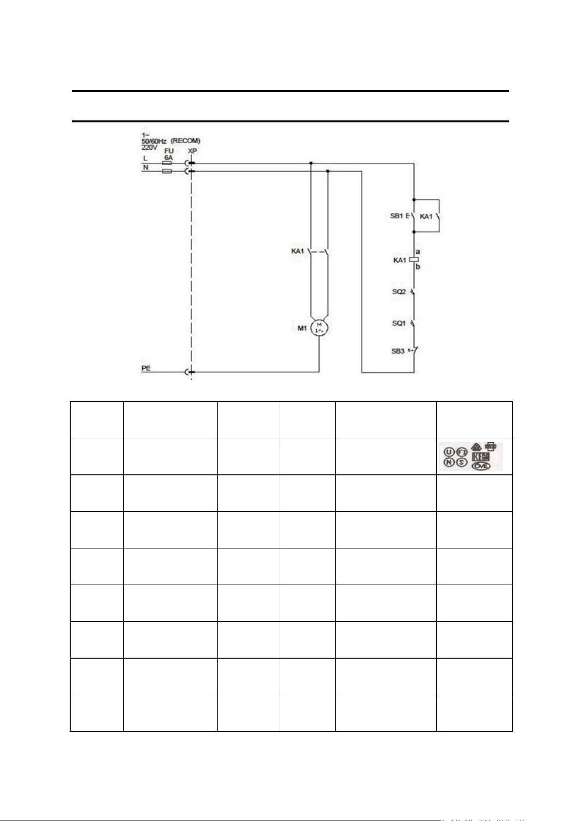
Item
designation
Description & function
Maker
Type
Technical data
Making of
conformity granted
XP
Plug for supply Three
phase
LIAN DUNG
LT-32
10~16A , 250V
Supply cable Three
phase
TIEN TUNG
H05W-F
3G 0.75m/m2 250V/440V
VDE/ROHS
SB1
Start switch
KED V
JD3
230V/10A
CE TUV
SB3
Emergency-Stop switch
XINQUANG
KB2-BE102
10A
CE
SQ1
Micro switch
HIEHLY
VS 10N
250V/10A
UL
KA1
Magnetic Conductor
KEDU
JD3
AC230V/50HZ 12A
CE TUV
M1
Motor
K & K
AC380V/50Hz 1420rpm
CE TUV
SQ2
Micro switch
Zhejiang Tiande
CT-303
250V/10A
CE
Electrical circuit diagram 213A
15/50
 Loading...