

Page 1

PROLINK®S7D 7.0x
PROLINK®S7D
Siemens SIMATIC S7-Protocol Driver
User Manual
©
PROLINK AG 310ManS7D70xEn.doc 2000-06-30
Page 2

PROLINK®S7D Siemens SIMATIC S7 Driver
TABLE of CONTENTS Page
PREFACE .......................................................................................................................................................... 3
INTRODUCTION................................................................................................................................................ 3
CONFIGURATION TABLES.............................................................................................................................. 4
S
IEMENS SIMATIC-S7 CONNECTIONS ..............................................................................................................4
AMPLE CONFIGURATION USING COML-S7 AND PG/PC TOOLS ........................................................................ 5
S
BJECT REFERENCE ................................................................................................................................. 6
ECI O
AMPLE CONFIGURATION OF COMMUNICATION OBJECTS.................................................................................... 8
S
A) Four ECI Objects for Statistics, Read, Write and Read/Write ................................................................ 8
B) Single ECI Object consisting of three partial Datasets........................................................................... 9
C) Single ECI Object with independent Read and Write Dataset ............................................................. 10
D) Dataset Exchange in Redundant System using PROLINK®VRN......................................................... 11
INFORMATION AND ERROR MESSAGES.................................................................................................... 12
PERFORMANCE CONSIDERATIONS............................................................................................................ 12
TROUBLE SHOOTING.................................................................................................................................... 13
AMPLE DEBUG FILE S7D.LOG ....................................................................................................................... 14
S
INSTALLATION AND AUTHORIZATION........................................................................................................ 15
P
ROGRAM ARGUMENTS................................................................................................................................... 16
YSTEM REQUIREMENTS................................................................................................................................. 17
S
PGRADE INFORMATION.................................................................................................................................. 17
U
IRST TIME INSTALLATION CHECKLIST ............................................................................................................. 18
F
GLOSSARY ..................................................................................................................................................... 20
©
1998-2000 by PROLINK AG, CH-5703 Seon, Switzerland. PROLINK is a registered trademark of PROLINK AG, Switzerland.
SIMATIC, SIMATIC NET and SINEC are registered trademarks of Siemens AG Germany.
FactoryLink is a registered trademark of United States Data Corporation, Richardson, Texas U.S.A.
Page 2 310ManS7D70xEn.doc
©
PROLINK AG
Page 3
Siemens SIMATIC S7 Driver PROLINK®S7D
PREFACE
It is assumed that the user of this manual is familiar with USDATA‘s Factorylink® software package incl.
PROLINK
configuration using the PG/PC and COML-S7 (Configuration Management Local) tools supplied with the
SOFTNET-S7 library as well as the NCM S7 and STEP 7 programming tools from Siemens.
Data and illustrations in this manual are not binding. Any information in this document is subject to change
without notice and does not represent a commitment on the part of PROLINK AG. PROLINK AG assumes no
responsibility for any errors that may appear in this document and is not responsible for any consequential or
incidental damage incurred by the use of this software. Note that references are indicated by a Ü sign.
®
ECI Enhanced Communication Interface and, especially with the SIMATIC NET installation and
INTRODUCTION
The PROLINK®S7D Siemens SIMATIC S7-Protocol Driver supports communication between the FactoryLink
and Siemens S7-300/400 series PLC through SIMATIC NET using the Siemens S7-Protocol. An ordinary
3COM Ethernet card is required to communicate through Industrial Ethernet TCP/IP or ISO, a Siemens
Profibus adapter is used for the Multipoint Interface MPI or PROFIBUS. Data is conducted through
PROLINK
®
ECI using the IMX Intertask Mail eXchange interface.
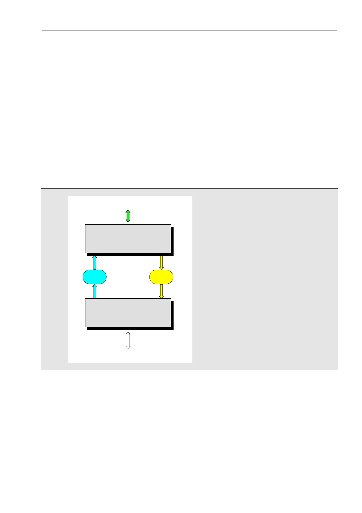
Object I/O Tags
Update Delay
ECI Object Information
RdElem(1) | I/O_Tag(1) | WrElem(1)
RdElem(2) | I/O_Tag(2) | WrElem(2)
RdElem(3) | I/O_Tag(3) | WrElem(3)
RdElem(x) | I/O_Tag(X) | WrElem(x)
Read Cycle Write Interval
ECI Converter
Action=Reaction
Decoder/Encoder
Scale/Normalize
Statistical Data
Indirect Addressing
Read
Mailbox
ECI Object Control
Dataset Exchange
Write
Mailbox
IMX Interface
Read/Write Dataset
SIMATIC-S7 ECI Object Reference
Dataset Definition
SIMATIC-S7 Connections
Network Device/Station Names
S7-Protocol Driver
Dataset Definition
Network Access
External Devices
SIMATIC NET Network System
S7-300/400 Series PLC
The PROLINK®ECI task is used to scale and convert Object I/O data from and to so called Datasets which
are transmitted through the IMX interface. Consider a Dataset being a number of words or bytes (Elements)
in a particular PLC. Then, Object I/O data is represented by words, bytes or bits in the PLC and, by individual
Database Elements in FactoryLink. Objects may be specified for Read-only, Write-only, Read/Write from/to
the same or different Datasets. For a simple system, the following items are required:
®
✔✔✔✔ FactoryLink
✔✔✔✔ PROLINK
✔✔✔✔ Siemens SOFTNET-S7/WindowsNT SAPI-S7 Library for PROFIBUS or Industrial Ethernet
Foundation System including PROLINK®ECI Converter Task
®
S7D Protocol Driver including PC adaptor for PROFIBUS or Industrial Ethernet
©
PROLINK AG 310ManS7D70xEn.doc Page 3
Page 4
PROLINK®S7D Siemens SIMATIC S7 Driver
CONFIGURATION TABLES
It is assumed that the SIMATIC NET configuration is studied and planned prior FactoryLink configuration.
This especially applies for names and addresses referenced. It is therefore recommended to get familiar with
the COML-S7 (Configuration Management Local) and PG/PC Interface set-up tools supplied with the
SOFTNET-S7 library from Siemens. Unless the Multipoint Interface MPI is applied, you must additionally
setup the PLC(s) Communication Processor with the NCM S7 and STEP 7 programming tools.
In the FactoryLink Configuration Explorer/Manager select the S7D Siemens SIMATIC S7-Protocol Driver
option in the SHARED folder/domain. Then select the desired panel(s) in order to configure or modify the
PLC communication links and its ECI Object References.
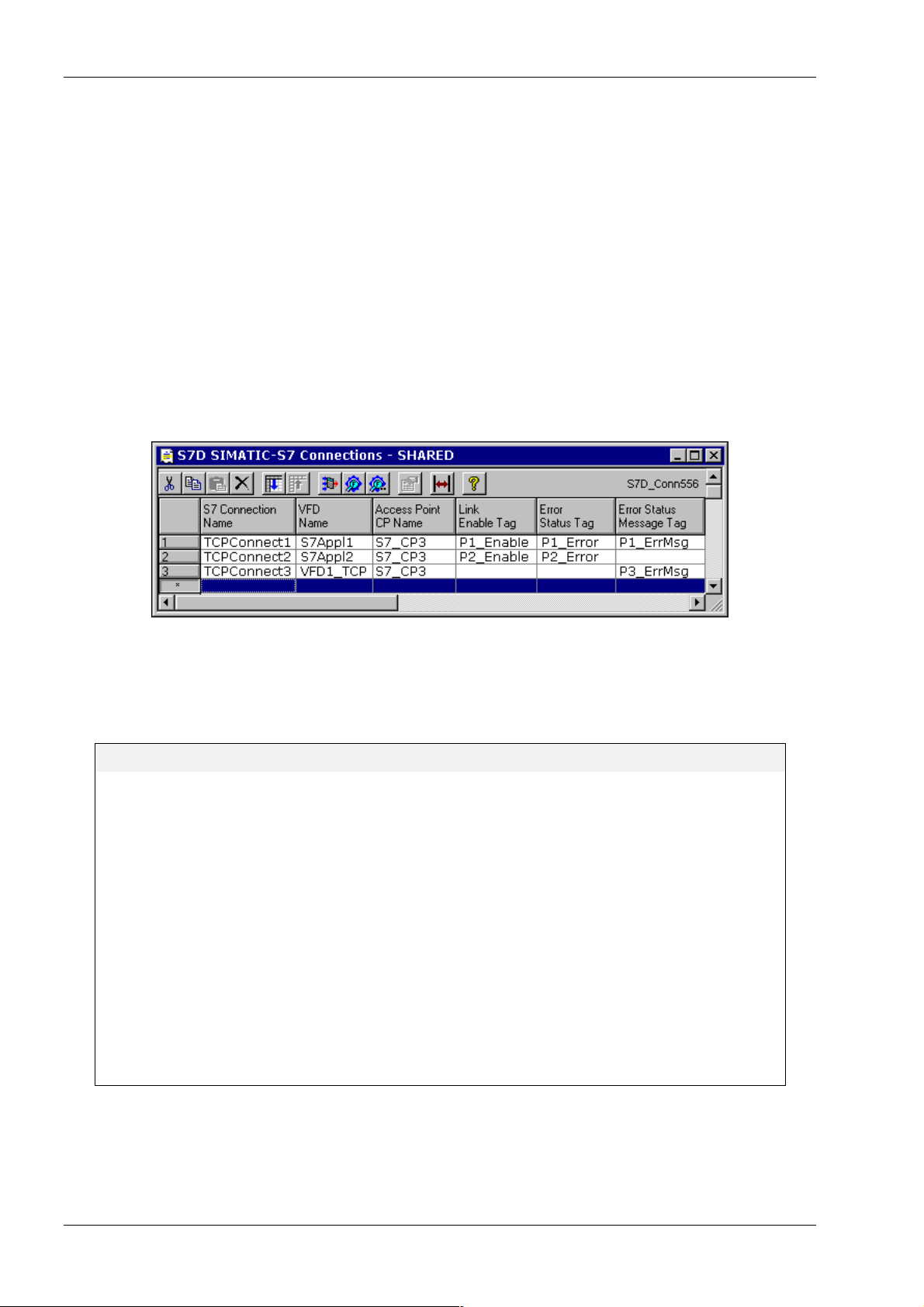
SIEMENS SIMATIC-S7 CONNECTIONS
The S7D Connections Table reflects the S7 connection list specified by the COML-S7 tool. A particular link is
defined as the connection of a Virtual Field Device VFD (PLC side) to an Access Point or Communication
Processor CP (FactoryLink side) as follows: S7 Connection = Virtual Field Device óóóó Access Point / CP
For configuration, enter an S7 Connection Name and its associated VFD Name (PLC side) and the local
Access Point or CP Name (FactoryLink side) to the appropriate columns. Note, all these names are
referenced only and defined at SIMATIC NET configuration as illustrated overleaf. Optionally you may specify
a tag name for Link Enable, Error/Status or Error/Status Message in order to indicate appropriate
information for each particular link.
S7D SIMATIC-S7 Connections (summary of table entries)
S7 Connection Name
(PLC ó FactoryLink)
VFD Name
(PLC side)
Access Point or CP Name
(FactoryLink side)
Link Enable Tag
Error Status Tag
Error Status Message Tag
Symbolic name of the communication link. The name of up to 32 char is
configured by the SIMATIC NET COML-S7 tool (Ü see overleaf and
corresponding Siemens documentation). It must be unique and represents
a pair of VFD and Access Point / CP.
Name of the Virtual Field Device. The name of up to 32 char is required
and configured by the SIMATIC NET COML-S7 tool (Ü see overleaf and
corresponding Siemens documentation). Note that pairs of VFD and
Access Point / CP must be unique.
Name of Access Point or Communication Processor. The name of up to
32 char is required and specified by the SIMATIC NET configuration when
setting up the PG/PC interface (Ü see overleaf and corresponding Siemens
documentation). Note, pairs of Access Point / CP and VFD must be unique.
Digital Tag (optional) to enable the link if ON
Analog Tag (optional) containing Error/Status number
For values displayed see ERROR and STATUS INFORMATION
Message Tag (optional) containing Error/Status information
For message displayed see ERROR and STATUS INFORMATION
For each S7 Connection you can specify one or several ECI Objects as described below. Press Enter and
then select the S7D ECI Object Reference Table.
Page 4 310ManS7D70xEn.doc
©
PROLINK AG
Page 5
Siemens SIMATIC S7 Driver PROLINK®S7D
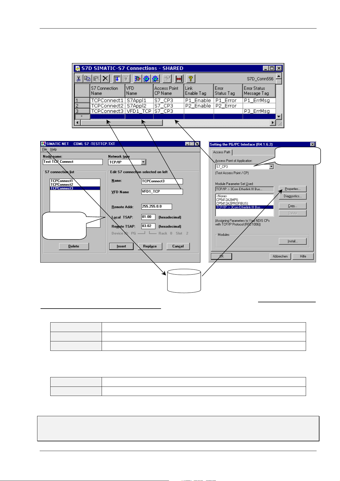
SAMPLE CONFIGURATION USING COML-S7 AND PG/PC TOOLS
Example of referenced names in the S7D SIMATIC-S7 Connections table:
Access Point
at FactoryLink
Local refers
to FactoryLink,
Remote refers
to PLC side
For SIMATIC NET configuration create a
binary database file xxx.ldb on harddisk by
selecting „File“ and „Generate Binary DB As...“
Harddisk
xxx.ldb
When setting up the PG/PC Interface,
refer to the binary database file xxx.ldb by
selecting „Properties...“
Make sure to assign a valid Module Parameter Set to create an Access Point i.e. DO NOT inadvertently
press OK when the <None> option is selected in the PG/PC Interface panel. Note that the SIMATIC NET
Node Name is for documentation only while the Remote Address depends on the Network type selected:
PROFIBUS
ETHERNET (ISO)
TCP/IP
Profibus/MPI Address = Station Address 0..126 (at PLC side)
Ethernet Address = 6 Pairs of hex numbers e.g. 08.00.06.01.00.00 (at PLC side)
IP Address = 4 Groups of 0..255 decimal e.g. 255.255.0.13 (at PLC side)
A SIMATIC NET Transport Service Access Point TSAP consists of exactly two groups in hex separated by
a period. You may try different numbers or consult Siemens to locate the Rack/Slot for the Remote TSAP:
Local TSAP
Remote TSAP
First group = Device ID normally set 01, second group must be 00 (for FactoryLink)
First group = Device ID normally set 03, second group = Rack/Slot of CPU (not CP !)
Please note that the Remote TSAP refers to the PLC’s CPU and NOT to its Communication Processor.
F For SIMATIC NET installation/setup refer to Ü Siemens CD Manuals for SIMATIC NET NCM S7
PROFIBUS or Industrial Ethernet chapter 1 (Communication) and chapter 2 (Installation/Commissioning).
Important! for the S7-Protocol no PLC programming (Send/Receive) is required.
©
PROLINK AG 310ManS7D70xEn.doc Page 5
Page 6
PROLINK®S7D Siemens SIMATIC S7 Driver
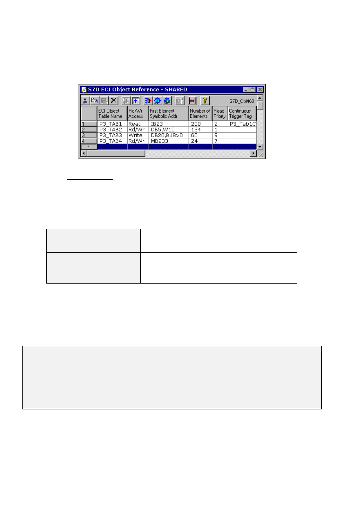
ECI OBJECT REFERENCE
The ECI Object Reference Table is used to specify one or several ECI Objects by addressing coherent
blocks (Datasets) of elements with contiguous addresses for the particular S7 Connection indicated at the
bottom of the panel. The table is displayed when selecting „Open inGrid“:
The first entry must be identical with the ECI Object Table where the specified Dataset (block of data) is
being scaled and converted to/from individual FactoryLink Database Elements. Because ECI can handle
partial Datasets (groups of Elements) as well as independent Read- and Write-Datasets for a particular
Object, the Reference Table accepts multiple entries for the same ECI Object (see examples). Objects may
be defined for Read-only, Write-only, Read/Write from/to the same Dataset as well as Read/Write from/to
different Datasets by specifying the corresponding Rd/Wr Access. Move the cursor to the appropriate
column and enter a name from the list as follows:
S7 Functions
(any number allowed per table)
Statistics Functions
(one of each type allowed per table or
one only for all tables, respectively)
Read Read only (polling by ECI or Timer)
Write Write only (Exception, Block or Dataset)
Rd/Wr Read and/or Write (any type as above)
SRD Statistics Read specific Device
SRDC Statistics Read specific Device and Clear
SRS Statistics Read Sum of all Devices
SRSC Statistics Read Sum of all Devices and Clear
The statistics functions provide quality and performance information on a particular or on all Symbolic
Devices. The information includes number of bytes read/written, CRC errors, jobs in queue etc. Data is polled
by triggering and displayed by 17 elements. It is decoded as shown for the Sample Configuration a) in the
next chapter or, you may dump the information to a LongAna array using the ARY Function of ECI. Functions
SRD and SRS use internal totalizers/counters which are set zero (cleared) only at shutdown of the system.
Functions SRDC and SRSC clear the counters after each poll request, i.e. the values indicate the counts
measured for a poll interval. This can e.g. be used to display the number of bytes transmitted every 10 sec.
Before accessing data in a PLC, carefully check whether all desired areas and addresses
are available else, you must allocate the required data first. This especially applies for
Counters and Timers which are not automatically created with consecutive addresses.
Although a Dataset consists of Bytes, Words or Doublewords, you may access any bit, nibble, byte,
short, long, float, message or array as specified in the ECI Information Table for both, read and write.
Apart from Block and Dataset Write commands, PROLINK-S7D also supports Exception Write
commands for any data type including Bit 0..7 for bytes of DB, DI, MB and OB.
Page 6 310ManS7D70xEn.doc
©
PROLINK AG
Page 7

Siemens SIMATIC S7 Driver PROLINK®S7D
Consider a Dataset being a number of Elements (Bytes, Words or Doublewords) which are transmitted by
one or several data blocks. In the First Element Symbolic Addr column specify the data area, type and
address ## of the first element for a coherent block of data being identified as a particular Dataset:
S7 Data Area / Data Type
(Element Size à)
DOUBLEWORD
(4 Bytes)
WORD
(2 Bytes)
BYTE
(1 Byte)
Data Block (standard recommended) DB##,D## DB##,W## DB##,B##
Data Instance DI##,D## DI##,W## DI##,B##
Memory Flag (Merker)
Input (Eingang)
Output (Ausgang)
Periphery Input
Periphery Output
Counter 0..999 Integer (read only)
Timer 0..999 Integer (read only)
MD## MW## MB##
ID## IW## IB##
OD## OW## OB##
PIW##
POW##
CW##
TW##
Read/Write Element Addr in ECI normally correspond to the SIMATIC-S7 addresses ## for any data type. I.e.
Word 12 uses byte addresses 12..13 or Doubleword 40 uses byte addresses 40..43 etc. while Counters and
Timers use word addresses. For relative addressing (First Addr = 0 in ECI), append an arrow right sign
followed by a zero „>0“ e.g. DB20,B18>0 will shift DB20 byte 18 to address 0 in ECI. You can force the
Dataset Element size (called Boundary) so that addresses become e.g. words as used for SIMATIC-S5 DB’s
Ü ECI Rd/Wr Mode = H2. The shaded fields above indicate the preferred symbolic expressions for the
particular areas. Note, Write commands for Bit 0..7 Ü ECI Wr CDE = 0..7 are allowed for DB, DI, MB and OB
of Datasets with a byte boundary.
In the Number of Elements column enter the length of the coherent block of Doublewords, Words or Bytes
to be accessed as a Dataset. Note, the size of a Dataset in bytes is expressed by the element size times the
number of elements entered and may not exceed the S7-PDU (Protocol Data Unit) size which depends on
the S7 PLC type and interface applied. Datasets larger than the allowed S7-PDU size will be truncated e.g. at
212 bytes for MPI. Check file Ü %flapp%\shared\log\S7D.log after start up of the driver to see the negotiated
S7-PDU size and allow for a 18 byte Read - or a 28 byte Write data header (to be subtracted). Note that for
ECI, a Dataset may be of any size between a single Element and 64 kBytes.
In the Read Priority column specify a number 1..9 which is valid for read access only. Note, priority 1
(default) provides 9 times faster polling than priority 9 if jobs are queued due to a high demand. An optional
Continuous Trigger Tag (Analog) may be applied for continuous polling while simultaneously controlling the
priority level. If the Analog tag’s value is zero, continuous polling is disabled, while a value of 1..9 enables
polling with the corresponding priority.
S7D ECI Object Reference (summary of entries)
ECI Object Table Name
Rd/Wr Access
First Element Symbolic Address
Number of Elements
Read Priority
Continuous Trigger Tag
Name of ECI Object Table used for decoding/encoding
The entry of up to 15 char is the reference to an ECI Control table.
Type of data transmission
See list of functions or see table above
Symbolic name of first element transmitted of Dataset
Syntax as specified by SIMATIC S7-Protocol
Maximum number of elements transmitted by a single Read or
Write request (see above) where an element is either a Byte, a
Word or a Doubleword. Consider the max. S7-PDU size in bytes
and allow for 2 bytes per Word or 4 bytes per Doubleword.
1..9 Priority (1=highest)
Analog Tag (option): Value 0=No continuous polling,
Value 1..9=Priority for continuous polling
©
PROLINK AG 310ManS7D70xEn.doc Page 7
Page 8

PROLINK®S7D Siemens SIMATIC S7 Driver
SAMPLE CONFIGURATION OF COMMUNICATION OBJECTS
A) Four ECI Objects for Statistics, Read, Write and Read/Write
Sample ECI Information Table for Object SIM1_STAT displaying satistical data by 17 LongAna elements. Note, for
statistics functions, the first element address is set zero and addressing is defined for doublewords:
ECI Object Information - SHARED
Alternate
ReadTag
Elem
AddrRdCDE
0 L0 Jobs_in_Write_Queue - -1
1 L0 Jobs_in_Read_Queue - -1
2 L0 Number_of_Bytes_written - -1
3 L0 Number_of_Bytes_read - -1
4 L0 Total_number_of_Bytes_transmitted - -1
5 L0 Read_CRC_Errors - -1
6 L0 Write_CRC_Errors - -1
7 L0 Read_Timout_Errors - -1
8 L0 Write_Timout_Errors - -1
9 L0 Write_Jobs_cancelled - -1
10 L0 Write_retries - -1
11 L0 Read_retries - -1
12 L0 Unexpected_Answers - -1
13 L0 Total_number_of_Errors - -1
14 L0 Read_Telegrams - -1
15 L0 Write_Telegrams - -1
16 L0 Total_number_of_Telegrams - -1
Object I/O
Tag
Wr
CDE
Elem
Addr
Alternate
WriteTag
R/W Range
Function
Sample ECI Control Table with four Objects using Read and Exception Write (Wr at Ch=X). Note, data for above table
is updated when the Dataset IdxTag RdS1_STAT is forced ON (Read Trigger):
ECI Object Control - SHARED
Object
Table Name
SIM1_STAT ReadMbx RdS1_STAT -1 H1 N N see ÈÈÈÈ
SIM1_OBJ10 ReadMbx RdS1Obj10 -1 H1 N N
SIM1_OBJ11 WriteMbx WrS1Obj11 -1 H1 N X
SIM1_OBJ12 ReadMbx RdS1Obj12 WriteMbx WrS1Obj12 -1 H1 N X
Names to be
referenced
Read
MailboxTag
Read Ds
IdxTag
Write EncArr
MailboxTag
Write Ds
IdxTagWrIdxWrModeWrTrWrCh
E Mailboxes and Datasets are
automatically referenced by S7D
S7D ECI Object Reference Table with four individual Communication Objects. Note, element addressing in ECI
correspond with S7 regardless of the element size specified by symbolic addressing:
S7D ECI Object Reference
ECI Object
Table Name
SIM1_STAT SRD MD0 17 (n/a) Statistics Read Device, MemoryDWord 0, 17 DWords see ÈÈÈÈ
SIM1_OBJ10 Read IB34 5 1
SIM1_OBJ11 Write DB230, B131 120 (n/a)
SIM1_OBJ12 Rd/Wr DB27,W44 20 9
R/W
Access
First Element
Symbolic Addr
Nr of
Elements
Read
Prio
Read Input Byte 34, 5 bytes with Priority 1
Write DataBlock 230, Byte 131, 120 bytes (Prio not applicable)
Read/Write DataBlock 27, Word 44, 20 words with Priority 9
Comment
Note, the ECI Information Tables for Objects STA1_OBJ10..12 are not displayed.
Page 8 310ManS7D70xEn.doc
©
PROLINK AG
Page 9

Siemens SIMATIC S7 Driver PROLINK®S7D
B) Single ECI Object consisting of three partial Datasets
The ECI Information Table for Object SIM1_OBJ3 below has a total of 30+12+20 Read Elements specified by three
blocks of Bytes in the S7D‘s Object Reference. Note that the Read Element Addressing is therefore in bytes. The 2
block is Read/Write and is transmitted bi-directionally for word 150..151, Write_only for word 152..151 or, Read/Write
with different locations for doubleword 188..191/154..157 etc. As an example, the Last_Float_of_3rd_Block is written
to address 158..161 however, the feedback is taken from bytes 204..207. This may be used to write a setpoint (158..) to
an Object I/O Tag which is simultaneously used to indicate the actual value (204..) from the plant.
ECI Object Information - SHARED
Alternate
ReadTag
Elem
AddrRdCDE
120 S0 First_Word_of_1st_Block - -1
122 S0 2nd_Word_of_1st_Block - -1
etc. S0 etc. - -1
148 S0 Last_Word_of_1st_Block - -1
150 S0 First_Word_of_2nd_Block S0 150
-1 LSB Write_only_Word_of_2nd_Block S0 152
etc. S0 etc. - -1
158 S0 Last_Word_of_2nd_Block - -1
Note that Elements (bytes) 160 through 187
are never updated (all Read values = zero)
188 UL0 First_DoubleWord_of_3rd_Block UL0 154
192 L0 2nd_DoubleWord_of_3rd_Block - -1
etc. S0 etc. - -1
204 F0 Last_Float_of_3rd_Block F0 158
Object I/O
Tag
Wr
CDE
Elem
Addr
Alternate
WriteTag
R/W Range
Function
nd
Sample ECI Control Table for triggered Block Write (Wr by Tr=B) and/or Exception Write (Wr at Ch=X). Note, the Wr
Mode is set to H1 for High_to_Low format (SIMATIC) and 1 byte element size (byte boundary):
ECI Object Control - SHARED
Object
Table Name
SIM1_OBJ3 ReadMbx RdS1Obj3 1/5 3 WriteMbx WrS1Obj3 -1 H1 B X see ÈÈÈÈ
Names to be
referenced
Read
MailboxTag
Read Ds
IdxTag
Interv
Ch/Cont
Upd
Delay
Write EncArr
MailboxTag
Write Ds
IdxTagWrIdxWrModeWrTrWrCh
E Mailboxes and Datasets are
automatically referenced by S7D
S7D ECI Object Reference Table with three entries for the same Communication Object. Note, object SIM1_OBJ3 is
split in 3 groups of elements (Bytes) with individual R/W Access and Read Priority:
S7D ECI Object Reference - SHARED
ECI Object
Table Name
SIM1_OBJ3 Read DB231,B120 30 4 Read DataBlock 231, Byte 120, 30 bytes with Priority 4
SIM1_OBJ3 Rd/Wr DB231,B150 12 1 Read/Write DataBlock 231, Byte 150, 12 bytes with Priority 1
SIM1_OBJ3 Read DB231,B188 20 9 Read DataBlock 231, Byte 188, 20 bytes with Priority 9
R/W
Access
First Element
Symbolic Addr
Nr of
Elements
Read
Prio
Comment
Note that data is read (updated) when triggering the ECI Ü Read Dataset IdxTag. There are several methods to trigger
this tag: Interval Timer, Math&Logic or simply enter an interval to the ECI Read Interv Ch/Cont column. Entering e.g. 1/5
will cause ECI to continuously trigger the tag every 5 sec while it will speed-up to 1 sec whenever you change (write) an
I/O tag of the ECI Information table. This may be handy as ECI automatically speeds-up communication whenever an
operator changes a value within a particular table.
It is recommended to read data back after writing i.e. use ECI bi-directional transmission for data to be written to a PLC.
This has the advantage that data can be changed by both, FactoryLink and PLC. In this case adjust the ECI Ü Read
Update Delay e.g. to 3 sec in order to allow for a proper feedback transmitted by the 1 sec Read Interval at Change (see
also ECI manual).
©
PROLINK AG 310ManS7D70xEn.doc Page 9
Page 10

PROLINK®S7D Siemens SIMATIC S7 Driver
C) Single ECI Object with independent Read and Write Dataset
The ECI Information Table for Read/Write Object SIM1_OBJ44 has 55*2=110 bytes (Read Elements) and 15*2=30
bytes (Write Elements) with different addresses for Read and Write. Note that not every line entry need to be bidirectional, any mix of Read-only, Write-only and Read/Write is allowed. Furthermore, Read and Write Element
addresses need not to be in a consecutive order as shown they may be scattered as required. And, data may
additionally be converted and scaled using the R/W Range Function column:
ECI Object Information - SHARED
Alternate
ReadTag
Sample ECI Control Table for triggered Dataset Write (Wr by Tr=D) and/or Exception Write (Wr at Ch=X) of
Read/Write Object SIM1_OBJ44 which is split in two independent Datasets for Read- and Write-only. Note, the Wr
Mode is set to H1 for High_to_Low format (SIMATIC) and 1 byte element size (byte boundary):
ECI Object Control - SHARED
Object
Table Name
SIM1_OBJ44 EciRmbx RdS1Obj44 -1 EciWmbx WrS1Obj44 -1 H1 D X see ÈÈÈÈ
Elem
AddrRdCDE
220 S0 First_Word_bi_directional S0 35
222 L0 Double_Word_read_only - -1
226 UB0 Unsigned_Byte_bi_directional S0 37 0,255
etc. etc. etc.
-1 LSB Double_Word_write_only L0 59
328 US0 Last_Word_bi_directional US0 63 0;10000
Read
MailboxTag
Read Ds
IdxTag
Object I/O
Tag
Rd
Idx
Write EncArr
MailboxTag
Wr
CDE
Write Ds
IdxTag
Elem
Addr
Alternate
WriteTag
Wr
IdxWrModeWrTrWrCh
R/W Range
Function
Names to be
referenced
E Mailboxes and Datasets are
automatically referenced by S7D
S7D ECI Object Reference Table for a single Communication Object SIM1_OBJ44 which is split in two separate
Datasets of Words for Read-only and Write-only. Note that element addressing in ECI correspond with S7 regardless of
the element size specified by symbolic addressing:
S7D ECI Object Reference - SHARED
ECI Object
Table Name
SIM1_OBJ44 Read IW220 55 4 Read Input Word 220, 55 words with Priority 4
SIM1_OBJ44 Write DB175,W35 15 (n/a) Write DataBlock 175, Word 35, 15 words (Prio not applicable)
R/W
Access
First Element
Symbolic Addr
Nr of
Elements
Read
Prio
Comment
For a sample setup of the same Object in a redundant system, see overleaf.
Note data is read (updated) when triggering the ECI Ü Read Dataset IdxTag. There are several methods to trigger this
tag: Interval Timer, Math&Logic or simply enter an interval to the ECI Read Interv Ch/Cont column. Entering e.g. 0.5/4
will cause ECI to continuously trigger the tag every 4 sec while it will speed-up to 0.5 sec whenever you change (write)
an I/O tag of the ECI Information table. This may be handy as ECI automatically speeds-up communication whenever an
operator changes a value within a particular table.
It is recommended to read data back after writing i.e. use ECI bi-directional transmission for data to be written to a PLC.
This has the advantage that data can be changed by both, FactoryLink and PLC. In this case adjust the ECI Ü Read
Update Delay e.g. to 3 sec in order to allow for a proper feedback transmitted by the 0.5 sec Read Interval at Change
(see also ECI manual).
Page 10 310ManS7D70xEn.doc
©
PROLINK AG
Page 11

Siemens SIMATIC S7 Driver PROLINK®S7D
D) Dataset Exchange in Redundant System using PROLINK®VRN
Assign the same VRN Connect Control Table a Tandem and a Local link to exchange Datasets through mailboxes
between redundant system NodeA and NodeB as shown below. Note that ECI and Driver use separate mailboxes which
are linked according to the actual Tandem Status. The Tandem Status can further be used to start/stop the local Driver if
assigned to its TASKSTART_S[x] tag of the System Configuration:
VRN Connect Control - SHARED
Connect
Table Name
ProlinkVRN DAEMON `ProlinkVRN
Partner TANDEM `TandemStation `ProlinkVRN TASKSTART_S[x]
Partner CLIENT `LocalStation `ProlinkVRN Mux=1 TASKSTART_S[x]
Local
Mode
*Host Name
or IP Addr
*Service
Name
Function and
Arguments
Local
Control Tag
Local
Status Tag
VRN Client Object Information - SHARED
Read from Server
(Element, Item)
DrvRmbx EciRmbx
I/O TAGName
(Wildcard)
EciWmbx DrvWmbx
Write to Server
(Element, Item)
The ECI Information Table for Object SIM1_OBJ44 shall e.g.
be the same as on the previous page.
VRN Mailbox Switching Diagram
Local
Server
NodeA
EciRmbx
EciWmbx
DrvRmbx
DrvWmbx
Tandem
EciRmbx
EciWmbx
DrvRmbx
DrvWmbx
Local
Client
NodeB
In the ECI Control Table assign a Rd/Wr Ds Idx e.g. 144 and 244 then, duplicate the line, add an asterisk to the table
name *SIM1_OBJ44 and rename the Mailboxes EciRmbx+EciWmbxàDrvRmbx+DrvWmbx in order to create a dummy
entry which is referenced by the S7D Driver:
ECI Object Control - SHARED
Object
Table Name
SIM1_OBJ44 EciRmbx RdS1Obj44 144 EciWmbx WrS1Obj44 244 H1 D X
*SIM1_OBJ44 DrvRmbx RdS1Obj44 144 DrvWmbx WrS1Obj44 244 H1 D X
Names to be
referenced
Read
MailboxTag
Read Ds
IdxTag
VRN Mailbox Data Exchange by Local or Tandem Connect
Rd
Idx
Write EncArr
MailboxTag
Write Ds
IdxTag
Wr
IdxWrModeWrTrWrCh
E Mailboxes and Datasets are
automatically referenced by S7D
S7D ECI Object Reference Table for Communication Object *SIM1_OBJ44 which is transmitted in a redundant system
to the Local and/or Partner station through VRN:
S7D ECI Object Reference - SHARED
ECI Object
Table Name
*SIM1_OBJ44 Read IW220 55 4 Read Input Word 220, 55 words with Priority 4
*SIM1_OBJ44 Write DB175,W35 15 (n/a) Write DataBlock 175, Word 35, 15 words (Prio not applicable)
R/W
Access
First Element
Symbolic Addr
Nr of
Elements
Read
Prio
Comment
If you do not want to control the Driver by VRN Tandem Status, replace above TASKSTART_S[x] tag by a unique tag.
Note that in any case, VRN must run for data exchange between ECI and Driver.
Note data is read (updated) when triggering the ECI Ü Read Dataset IdxTag. There are several methods to trigger this
tag: Interval Timer, Math&Logic at the local system or enter Ü Rd Mode = Suffix M (read by Maibox request) and an
interval to the ECI Read Interv Ch/Cont column at the remote system. Entering e.g. Ch/Cont = 1/5 will cause ECI to
continuously trigger the tag every 5 sec while it will speed-up to 1 sec whenever you change (write) an I/O tag of the ECI
Information table. This may be handy as ECI automatically speeds-up communication whenever an operator changes a
value within a particular table (see also ECI manual).
©
PROLINK AG 310ManS7D70xEn.doc Page 11
Page 12

PROLINK®S7D Siemens SIMATIC S7 Driver
A
INFORMATION and ERROR MESSAGES
The following messages may be displayed in the RunTime Manager:
Label in S7D.TXT
START
RUN
STOP
DEMORUN
DEMOSTOP
NODEMO
NO_AUTHORIZATION
CTRECORD
CTREC
DEVOPEN
NOSERVER
FOPENARG
PROGENVVAR
FSETARG
PROG_PARA_UNKNOWN
Messages reported by RunTime Manager
S7D Vx.xx starting
S7D Vx.xx running
S7D Vx.xx normal shutdown
#001 Demo running: Shutdown by timeout
#002 Demo stopped: Shutdown by timeout
#003 Demo restart prevented: Shutdown FL first
#100 Option not installed or License not enabled
àààà Check that the Option Key is installed using UKEY –L utility.
Verify the Lincense is enabled by running the KEYINST and FLKEYVAL utilities.
#101 Error reading CT record à CT file may be corrupted
#102 Bad record data à CT file may be corrupted
#103 Error opening COM Device à check COML-S7 configuration
#104 Server not running à check PLC links
#105 Cannot open Programm Argument File
#106 Cannot read Environment Variables
#107 Cannot set Programm Argument
#108 Unkown Parameter or Programm Argument in File
The following messages and values are displayed by the element(s) entered to the S7D Connection table:
Label in S7D.TXT
E0
E50
E51
E52
E-1
E-7
E-14
E-15
E-16
E-17
E-18
E-19
E-50
lso indicated
by ECI Warning
#021 Table %s
RAPD Error ...
Error/Status generated by S7D and reported to Message Tag or Analog Tag Value
#200 Link normal 0
#250 Link terminated 50
#251 Link inactive 51
#252 Link disabled 52
#301 No response from Station à check PLC links -1
#307 Wrong Station Address à check COML-S7 configuration -7
#314 Retry Timeout à check SIMATIC NET or Programm Arguments -14
#315 Illegal Response received (Order ID) -15
#316 Illegal Response received (CREF) -16
#317 Active Abort from PLC -17
#318 Read Error from PLC -18
#319 Write Error to PLC -19
#350 Data in PLC not found -50
PERFORMANCE CONSIDERATIONS
The S7-Protocols cyclic read method is essentially an automatic polling by the receiving station, this method
is not implemented in favor of the Ü Continous Trigger Tag in the S7D Object Reference table. When this tag
is set to a value of 1 (Read Priority=1) the corresponding object will be polled as fast as possible however,
still allowing for all other object data to be processed. Under this condition you may measure the number of
telegrams and bytes transmitted using the statistics function as shown for the Ü Sample Configuration A).
For TCP/IP, approx. 10 Datasets of 200 bytes (S7-300/400 at ~20 ms CPU cycle time) were measured per
second with a 3COM card on a 200MHz PC through a single connection, i.e. approx. 2 kbytes/sec. These
figures may be reduced with increasing CPU cycle time or when adding connections to a particular CP
(S7-300 allows only for two connects). For a single connection, MPI may be as powerful as Ethernet. Another
limiting factor is the PDU size (Protocol Data Unit) which depends on the PLC’s CPU and CP type applied.
The PDU size defines the maximum Ü Number of Elements which can be transmitted by s single transaction.
Note that these limitations are not due to S7D or ECI as they could handle 1000 Datasets or 200 kbytes/sec
under the same condition. S7D could handle PDU sizes of up to 8'192 bytes by a single transaction.
An other point which may be considered is that the S7 CPU‘s allow for a data consistent block of only 8 bytes
(CPU31x) or 32 bytes (CPU41x) respectively. This means, when reading e.g. recipes of more than 8 or 32
bytes, the user must take care for data consistency in the application (data synchronization).
Page 12 310ManS7D70xEn.doc
©
PROLINK AG
Page 13

Siemens SIMATIC S7 Driver PROLINK®S7D
TROUBLE SHOOTING
Note that S7D has been designed for the SOFTNET SAPI-S7 library from Siemens in order to keep PLC
communication and its associated problems within the domain of the PLC experts. The IMX interface toward
FactoryLink is well tested and runs in many applications. On the other hand, the interface for SOFTNET-S7 is
specified by three only items: Ü S7 Connection Name, VFD Name and Access Point.
A great deal of the setup is related to Siemens instructions which, if strictly followed, will provide you with a
successful installation. If the SOFTNET-S7 library, the underlying network (Ethernet, PROFIBUS or MPI) and
the S7 PLC’s with its Communication Processors are properly installed and setup as described in the
Siemens documentation, S7D should work without a problem. Thus, before calling for support on S7D,
please carefully check the following items first:
Make sure to apply the latest Version of SOFTNET-S7 and CP Firmware Revisions from Siemens
à Check SIMATIC Customer Support on Internet or consult Siemens.
à After installation, it may be advisable to re-install the required WindowsNT Service Pack from Microsoft.
It may be cumbersome to determine a Rack/Slot number for the Remote TSAP at COML-S7 setup
à This must be the Rack/Slot of the PLC’s CPU (not CP), you may try with different numbers 01..05 or consult Siemens
Verify your PLC Communication Processor is configured properly for SIMATIC NET
à Check to have the NCM S7 option installed for the STEP 7 configuration
If S7D cannot communicate with a PLC
à Carefully check the entries for „S7 Connection Name“, „VFD Name“ and „Access Point“
as they may include special characters as colon etc. (e.g. CP_L2_1:)
à MCI/PROFIBUS: Check the station addresses live, using the PC/PG tools „Diagnostic“ menu
à TCP/IP: Check the CP’s address live using the „ping [IP address]“ command from a DOS Window
à ISO: Carefully verify all Ethernet addresses and TSAPs as there is no runtime check tool
à The total number of connects are limited depending on the PLC type and/or SOFTNET-S7 library
Note that TCP/IP connection/reconnection takes time
à According to Siemens, TCP/IP may be slow to connect, this also applies when switching a CP Off and On
Note that PLC memory access may be slow since it is synchronized with the CPU cycle
à If the cycle time is e.g. 100 ms, a max of 10 Read+Write jobs/sec are possible for a particular connection
à Use ECI‘s Action/Reaction method for commands sent-to and read-back from the PLC
à Use multiple connections to split „fast“ and „slow“ jobs
Increasing the number of connections to a PLC drops data troughput for an actual connect
à This depends on the PLC Communication Processor, use the Ü Read Priority of S7D to tune your system
Check Debug and Log Information in file {flapp}\shared\log\S7D.log (see sample file overleaf)
àààà Adjust a Verbose Level 1...63 as desired for the approprate Ü Program Argument.
Caution! a Verbose Level greater than 15 may overflow your harddisk quickly.
à Note, the braces at the end of a line „...->(err: %d, %s)“ displays the exact error nr+text from the SAPI-S7 library.
If a link is frequently down and being reconnected
à Check the network load, it may be high due to other partners e.g. due to file transfer etc.
à In S7D.log compare the avarage Response Checks with Ü Program Argument „TimeoutFactor“
à If Response Check counts > TimeoutFactor, tune TimeoutFactor or possibly SleepTime
à Else tune Ü Program Argument S7_MINI_DB_ABORT_TIMEOUT
If a Dataset from/to a PLC is not or partially transmitted only
à Make sure all data accessed in a PLC has been created, for Timer/Counter prevent address gaps
à In the S7D.log file check the PDU size negotiated, the lower value found for S7D or PLC will be applied.
Allow for an 18 byte Read - and a 28 byte Write data header, for example:
S7-300 PDU size = 240 bytes à Read Dataset may be 212 bytes max, Write Dataset may be 202 bytes max.
S7-400 PDU size = 480 bytes à Read Dataset may be 462 bytes max, Write Dataset may be 452 bytes max.
Any Datasets longer than the PDU size minus the data header will be truncated accordingly.
Block Read Data is not synchronized
The S7 CPU‘s allow for a data consistent block of only 8 bytes (CPU31x) or 32 bytes (CPU41x) respectively.
à
à Use the Ü ECI Read Complete Trigger to synchronize. Use Dataset chaining by triggering the following
Dataset with the Complete Trigger of the previous Dataset for data blocks larger than the PDU size.
Before consulting Siemens, setup a trace file to gather more information
à Setup a trace file (default „s7trace.txt“) by PC/PG tool „Diagnostic“. Functions are described in Ü Siemens SAPI-S7
documentation „SOFTNET-S7“ „S7 Programming Interface“ „S7_MINI_DB...“ and check appropriate Ü Program
Arguments. Note, modified Trace Functions are only accepted after restartig S7D.
Some SOFTNET-S7 Parameters may be adjusted in the Registry using REGEDIT
à Do not adjust these Parameters unless clearly advised by Siemens.
©
PROLINK AG 310ManS7D70xEn.doc Page 13
Page 14

PROLINK®S7D Siemens SIMATIC S7 Driver
SAMPLE DEBUG FILE S7D.LOG
Debugfile:D:\mmisampl\shared\log\S7D.log with Debugstate has opened:63 at: 2000-06-30 14:07:22
Startup Messages of the driver .............................. (1) ON
Startup Errors of the driver ................................... (2) ON
Data read transfer Errors of the driver .................. (4) ON
Data write transfer Errors of the driver ................. (8) ON
Logging of the read Datarequests ...................... (16) ON
Logging of the write Datarequests ....................... (32) ON
For setup, see Ü Program Arguments.
To prevent harddisk overflow, DO NOT
leave Verbose Level greater than 15
Initialize S7 Connection
Header and Verbose Information
Message: 2000-06-30 14:07:22.010-> START OPEN DEVICE: CP_NAME:S7_CP3, VFD_NAME:VFD1, CONNECT_NAME:PLC_15
Message: 2000-06-30 14:07:22.023-> CONNECT_NAME:PLC_15-> S7_GET_DEVICE has been found !!!
Message: 2000-06-30 14:07:22.036-> CONNECT_NAME:PLC_15-> S7_GET_VFD has been found !!!
Message: 2000-06-30 14:07:22.047-> CONNECT_NAME:PLC_15-> S7_INITIATE_REQ ok !!!
Message: 2000-06-30 14:07:22.052-> CHECK OPEN DEVICE: CP_NAME:S7_CP3, VFD_NAME:VFD1, CONNECT_NAME:PLC_15
Message: 2000-06-30 14:07:22.062-> CONNECT_NAME:PLC_15-> S7_RECEIVE-> ok (ret=0) !!!
Message: 2000-06-30 14:07:34.093-> CHECK OPEN DEVICE: CP_NAME:S7_CP3, VFD_NAME:VFD1, CONNECT_NAME:PLC_15
Message: 2000-06-30 14:07:34.108-> CONNECT_NAME:PLC_15-> S7_RECEIVE ok (ret=257) !!!
Message: 2000-06-30 14:07:34.116-> FINISH OPEN DEVICE: CP_NAME:S7_CP3, VFD_NAME:VFD1, CONNECT_NAME:PLC_15 (ACTIVE PDU-SIZE:240)
... further Response Checks...
Begin Data Transmission
Message: 2000-06-30 14:07:34.124-> READ: orderid:1, PLC-Address:DB110,B0
Message: 2000-06-30 14:07:34.137-> READ: Symbolic Variable Address:DB110,B0,180 !!!
Message: 2000-06-30 14:07:34.142-> receive:0, orderid:1, active_orders:1
Message: 2000-06-30 14:07:34.151-> receive:0, orderid:1, active_orders:1
Message: 2000-06-30 14:07:34.332-> receive:769, orderid:1, active_orders:1
Message: 2000-06-30 14:07:34.349-> S7_GET_READ_CNF -> OK (25,12,64,0,4,5,0,0,0,0,0,26,0,0,0,0,0,0,0,0)
... further Response Checks...)
PDU Size in Bytes
negotiated with PLC
Start Next Job
Message: 2000-06-30 14:07:34.362-> READ: orderid:2, PLC-Address:DB08,B0
Message: 2000-06-30 14:07:34.376-> READ: Symbolic Variable Address:DB8,B0,60 !!!
Message: 2000-06-30 14:07:34.388-> receive:0, orderid:2, active_orders:1
Message: 2000-06-30 14:07:34.394-> receive:0, orderid:2, active_orders:1
Message: 2000-06-30 14:07:34.502-> receive:769, orderid:2, active_orders:1
Message: 2000-06-30 14:07:34.516-> S7_GET_READ_CNF -> OK (-46,11,0,0,0,0,0,0,0,0,0,0,0,0,0,0,0,0,0,0)
... further Response Checks...
First 20 Bytes
of Dataset
Start Next Job .... etc. etc. etc.
Message: 2000-06-30 20:17:33.044-> READ: orderid:14425, PLC-Address:DB110,B0
Message: 2000-06-30 20:17:33.057-> READ: Symbolic Variable Address:DB110,B0,180 !!!
Message: 2000-06-30 20:17:33.066-> receive:0, orderid:14425, active_orders:1
Message: 2000-06-30 20:17:33.074-> receive:0, orderid:14425, active_orders:1
Message: 2000-06-30 20:17:33.172-> receive:769, orderid:14425, active_orders:1
Message: 2000-06-30 20:17:33.181-> S7_GET_READ_CNF -> OK (25,12,64,0,4,5,0,0,0,0,0,2,0,0,0,0,0,0,0,0)
Message: 2000-06-30 20:17:33.197-> READ: orderid:14426, PLC-Address:DB08,B0
Message: 2000-06-30 20:17:33.209-> READ: Symbolic Variable Address:DB8,B0,60 !!!
Message: 2000-06-30 20:17:33.214-> receive:0, orderid:14426, active_orders:1
Message: 2000-06-30 20:17:33.227-> receive:0, orderid:14426, active_orders:1
Message: 2000-06-30 20:17:34.353-> receive:0, orderid:14426, active_orders:1
Error: 2000-06-30 20:17:34.368-> READ: S7_RECEIVE (TIMEOUT): 0, there was no error
... further Response Checks...
Example of Timeout
... too many Response Checks cause a timeout...
Timeout: compare
Response Checks counts
with Ü Program Argument
„TimeoutFactor“
Data Returns Too Late à this is considered an error by displaying the mailbox contents:
Error: 2000-06-30 20:17:34.371-> MBX.mm_msg.m_len:128, MBX.mm_mbx:65535:65535, MBX.mm_type:0x3, MBX.mm_user1:0x0, MBX.mm_user2:7602176
Error: 2000-06-30 20:17:34.380-> ECIHEAD.version:0x1, ECIHEAD.handling:0x0, ECIHEAD.format:0x1, ECIHEAD.boundary:0x1
Error: 2000-06-30 20:17:34.392-> ECIHEAD.elements:60, ECIHEAD.elementaddr:0, ECIHEAD.cde:0xc00
Reconnect
Message: 2000-06-30 20:17:38.006-> START OPEN DEVICE: CP_NAME:S7_CP3, VFD_NAME:VFD1, CONNECT_NAME:PLC_15
Message: 2000-06-30 20:17:38.014-> CONNECT_NAME:PLC_15-> S7_GET_DEVICE has been found !!!
Message: 2000-06-30 20:17:38.020-> CONNECT_NAME:PLC_15-> S7_GET_VFD has been found !!!
Message: 2000-06-30 20:17:38.031-> CONNECT_NAME:PLC_15-> S7_INITIATE_REQ ok
Message: 2000-06-30 20:17:38.045-> CHECK OPEN DEVICE: CP_NAME:S7_CP3, VFD_NAME:VFD1, CONNECT_NAME:PLC_15
Message: 2000-06-30 20:17:38.052-> CONNECT_NAME:PLC_15-> S7_RECEIVE ok (ret=0) !!!
Message: 2000-06-30 20:17:50.011-> CHECK OPEN DEVICE: CP_NAME:S7_CP3, VFD_NAME:VFD1, CONNECT_NAME:PLC_15
Message: 2000-06-30 20:17:50.027-> CONNECT_NAME:PLC_15-> S7_RECEIVE ok (ret=257) !!!
Message: 2000-06-30 20:17:50.035-> FINISH OPEN DEVICE: CP_NAME:S7_CP3, VFD_NAME:VFD1, CONNECT_NAME:PLC_15 (ACTIVE PDU-SIZE:240)
... further Response Checks...
Restart Normal Processing
Message: 2000-06-30 20:17:50.042-> READ: orderid:14427, PLC-Address:DB09,B0
Message: 2000-06-30 20:17:50.055-> READ: Symbolic Variable Address:DB9,B0,210 !!!
Message: 2000-06-30 20:17:50.066-> receive:0, orderid:14427, active_orders:1
Message: 2000-06-30 20:17:50.072-> receive:0, orderid:14427, active_orders:1
Message: 2000-06-30 20:17:50.182-> receive:769, orderid:14427, active_orders:1
Message: 2000-06-30 20:17:50.194-> S7_GET_READ_CNF -> OK (1,15,0,0,0,0,0,0,0,0,0,0,0,0,0,0,0,0,0,0)
... further Response Checks...
Start Next Job .... etc. etc. etc.
Note, a possible error is displayed with the exact SAPI-S7 error number+text in braces at the end of a line by „...àààà(err: %d, %s)“
Page 14 310ManS7D70xEn.doc
©
PROLINK AG
Page 15

Siemens SIMATIC S7 Driver PROLINK®S7D
INSTALLATION and AUTHORIZATION
Insert the FactoryLink CD (Value Added Products) to drive x: or open a possible upgrade .zip file.
● Now browse the media to select x:\vap\s7d\setup.exe or setup.exe in the .zip file and press Enter then,
follow the instructions. Completion will be indicated by a message.
After the installation above, add the task to the RunTime Manager screen as described for FactoryLink
under Ü Adding New Tasks Fundamentals manual:
● In the Configuration Explorer/Manager select the System Configuration in the SHARED folder/domain.
● Add the required information to the end of the System Configuration Information panel using Copy and
Paste and assign the new task’s element names the next available array dimension. In the Flags column
enter FR, set the Task Name column to S7D, enter a description as e.g. PROLINK-S7D and the
Executable File column to BIN/S7D then, select Enter to save the information.
☞ PROLINK-S7D requires PROLINK-ECI to run. Therefore, you should have PROLINK
described in its manual.
Authorization
The license is enabled by the standard FactoryLink authorization number which is optained from USDATA or
via your supplier. For registration refer to Ü the FactoryLink Installation Guide. Check the Option bit contents
by typing UKEY –L in the Run dialog. Use KEYINST to (re)enter configuration information then, run KEYVAL
and follow the instructions for registration.
-
ECI installed as
SOFTNET-S7 Driver Library Installation
For SIMATIC NET installation/setup refer to Ü Siemens CD Manuals for SIMATIC NET NCM S7
PROFIBUS or Industrial Ethernet chapter 1 (Communication) and chapter 2 (Installation/Commissioning).
Important! for the S7-Protocol no PLC programming (Send/Receive) is required.
The SOFTNET-S7 Driver Library is installed and set-up according to the instructions supplied by Siemens.
Insert the SIMATIC NET CD in the CD-ROM drive and – unless automatically started - click on StartàRun in
the Windows Taskbar to display the Run dialog and enter or click on e.g. x:\setup.exe, where x denotes the
CD-ROM drive. Note, it is recommended to check the readme.txt file and product informations on the CD
prior starting with any installation. Now press the Software Installation button, select the setup language and
follow the instructions displayed. You may discard „Run automatic authorization“ and later authorize the
software. Now choose the components to be installed by clicking the desired check box(es). A SOFTNET-S7
module is required, other software depends on the network type and interface card to be installed.
Important! carefully read all Siemens instructions and cleary notify all SIMATIC NET names, addresses and
directories to be referenced as they may be used at configuration and conflicts may cause troubles.
To configure PLC communication processors you need the NCM S7 option for the STEP 7 programming tool.
Make sure to have the latest Version of SIMATIC NET SOFTNET-S7 and Service Pack(s) from Siemens and
verify the Firmware Revision of your S7-300/400 PLC(s) and Communication Processor(s).
©
PROLINK AG 310ManS7D70xEn.doc Page 15
Page 16

PROLINK®S7D Siemens SIMATIC S7 Driver
PROGRAM ARGUMENTS
The only Program Argument accepted in the System Configuration Table (see Ü Adding New Tasks) is the
verbose argument –V63 explained below. You can however reference a file, in order to specify multiple
arguments as listed below. In this case enter a filename without a leading dash and specify pathnames
and/or environment variables in braces {...} as e.g. {flink}\opt\S7D_para.run. Note that argument names are
case insensitive. A sample Program Argument file is on the installation media and may look as follows:
# S7D_para.run Program Argument File
# **********************************
# This is a sample program argument file. If you want S7D to read the arguments from this file, just insert the
# file’s name together with its path to the program argument column of the System Configuration Table.
# This is helpful for tuning S7D since you need not to shutdown FactoryLink but you may stop S7D, manipulate
# the program argument file and restart S7D. Valid program arguments are shown below. Please note the following:
# Caution! Program arguments – if wrongly adjusted - may cause unpredictable results
# Lines beginning with a number sign (#), an asterisk (*) or a space ( ) are considered comments and thus not
# being processed. The examples below may be enabled by removing the characters indicating a comment line.
#
# Program Arguments for Debugging:
# Verbose Level 1..63 for debugging and logging information to file = {flapp}\shared\log\S7D.log
# The level is identified as the sum of binary values each of enabling a log action in order to display ...
# 1 = Startup Messages of the driver 2 = Startup Errors of the driver
# 4 = Data Read transfer Errors of the driver 8 = Data Write transfer Errors of the driver
# 16 = Logging of the Read Data Requests 32 = Logging of the Write Data Requests
# Enter value 63 (=1+2+4+8+16+32) to enable all actions, DEFAULT=15 enabling actions 1+2+4+8:
# -V15
# (Note, the only program argument accepted directly in the System Configuration table is -V63)
#
# Program Arguments for Tuning:
# Adjust process speed / CPU load by suspending program every scan, DEFAULT=10 [ms]:
# -SleepTime10
# Factor for number of response checks before a timeout (TimeoutFactor*SleepTime) error is set, DEFAULT=1000:
# -TimeoutFactor1000
#
# Parameters for S7 Connections:
# (See ÜÜÜÜ Siemens SAPI-S7 documentation „SOFTNET-S7“ „S7 Programming Interface“ „S7_MINI_DB...“)
# Number of simultaneous jobs allowed to receive by active partner, DEFAULT=3, subject to negotiate with PLC:
# -S7_MINI_DB_INIT_REQ_AMQ_CALLING3
# Number of simultaneous jobs allowed to send by active partner, DEFAULT=3, subject to negotiate with PLC:
# -S7_MINI_DB_INIT_REQ_AMQ_CALLED3
# Protocol Data Unit size of active partner (max 8192), DEFAULT=960 [bytes], subject to negotiate with PLC:
# -S7_MINI_DB_INIT_REQ_PDU_SIZE960
# Number of simultaneous jobs allowed to receive by passive partner, DEFAULT=3, subject to negotiate with PLC:
# -S7_MINI_DB_INIT_RSP_AMQ_CALLING3
# Number of simultaneous jobs allowed to send by passive partner, DEFAULT=3, subject to negotiate with PLC:
# -S7_MINI_DB_INIT_RSP_AMQ_CALLED3
# Protocol Data Unit size of passive partner (max 8192), DEFAULT=960 [bytes], subject to negotiate with PLC:
# -S7_MINI_DB_INIT_RSP_PDU_SIZE960
# Max number of transmission attempts / retries before aborting an active connection, DEFAULT=5 [counts]
# -S7_MINI_DB_PERSISTANCE_COUNT5
# Time allowed for retries or to establish an active connection, DEFAULT=300 [51 ms] (i.e. 300*51 = 15‘300 ms)
# -S7_MINI_DB_ABORT_TIMEOUT300
#
# WindowsNT Task Priority Arguments
# You may specify the S7D Task Priority Class and Thread Priority as described in the sample file S7D_para.run.
# Warning! these arguments may cause undesired results and should only be adjusted by WindowsNT experts !!
#
Page 16 310ManS7D70xEn.doc
©
PROLINK AG
Page 17

Siemens SIMATIC S7 Driver PROLINK®S7D
SYSTEM REQUIREMENTS
❏❏❏❏ FactoryLink® Ver6.6x or Ver7.0x for WindowsNT/95/98
®
❏❏❏❏ PROLINK
❏❏❏❏ PROLINK
❏❏❏❏ Siemens SOFTNET-S7 Library for PROFIBUS and Multipoint Interface MPI using S7-Protocol
(includes SIMATIC NET configuration tools, for actual order information see Siemens catalogue)
Option a) SOFTNET-S7/WindowsNT for PROFIBUS with CPU controlled stack 6GK1704-5CW00-3AA0
Option b) S7-5412/WindowsNT for CP5412A2 for „on-board“ protocol stack 6GK1702-5CB00-3AA0
❏❏❏❏ Siemens PC Interface Adaptor Boards for PROFIBUS and Multi Point Interface MPI
(uses CP342-5, CP343-5 or CP443-5 at PLC, for actual order information see Siemens catalogue)
For
option a) CP5511 or newer (PCMCIA) for LapTop CPU controlled stack 6GK1551-1AA00
For option a) CP5611 or newer (PCI) for CPU controlled stack 6GK1561-1AA00
For option b) CP5412A2 or newer (ISA) „on-board“ protocol stack (recommended for MPI) 6GK1541-2BA00
(Note that CP5411 (ISA) may be incompatible with some PC’s memory allocation)
❏❏❏❏ Siemens SOFTNET-S7 Library for Industrial Ethernet using S7-Protocol
(includes SIMATIC NET configuration tools, for actual order information see Siemens catalogue)
Option c) SOFTNET-S7/WindowsNT for Industrial Ethernet CPU ctrld stack, 8 connects 6GK1704-1CW00-3AA0
Option d) SOFTNET-S7/WindowsNT for Industrial Ethernet CPU ctrld stack, 64 connects 6GK1704-1CX00-3AA0
Option e) S7-1413/WindowsNT for „on-board“ protocol stack (upgrade for CP1413) 6GK1701-1CB00-3AA0
Option f) S7-NET1413/WindowsNT includes the CP1413 (ISA) adaptor board (hardware) 6GK1141-3CB00
ECI Enhanced Communication Interface for above FactoryLink System
®
S7D Siemens SIMATIC S7-Protocol Driver for above FactoryLink System
❏❏❏❏ Siemens PC Interface Adaptor Boards for Industrial Ethernet
(uses CP343-1, CP343-1 TCP, CP443-1 or CP443-1 TCP at PLC, for order information see Siemens catalogue)
For o
ption c or d) CP1411 or newer (ISA) for CPU controlled stack 6GK1141-1AA00
For option c or d) CP1511 or newer (PCMCIA) for LapTop CPU controlled stack 6GK1151-1AA00
For option c or d) 3COM for CPU controlled stack (card from any supplier)
For option e or f) CP1413 available or included in S7-NET1413/WindowsNT package (card only not available)
Make sure to have the latest Version of SIMATIC NET SOFTNET-S7 and Service Pack(s) from Siemens
àààà check SIMATIC Customer Support on Internet http://www4.ad.siemens.de/csinfo/livelink
UPGRADE INFORMATION
F Check the latest version on http://www.prolink.ch and download the desired product(s) and manual(s). The
following is a brief summary of enhancements and bugs resolved:
Ver7.0x New compiled version for FactoryLink 7.0x using Siemens SAPI-S7 Library of November 1999.
„PROLINK-“ in panel titles removed.
Ver6.6x New compiled version for FactoryLink 6.6x. Bug resolved with regard to invalid Write access. New
configuration check with regard to Read and Write access. Online Configuration implemented by method
BUMP. New CD installation media for PC’s supporting USDATA authorization with FLKEYVAL and UKEY –L.
Additional Program Arguments and Program Argument File. Bug with priority control at high load resolved.
Bug with Word DWord syntax resolved. First Element Addr syntax extended for relative addressing
(appending „>0“). Error numbers #3xx now indicated by ECI „#021 Table %s RAPD Error xx=0xhhh“.
Includes previous Ver6.5x: (Authorization code from PROLINK to be entered to file %flink%\opt\prolink.key).
English text in log file. Independent link supervision and shutdown. Error in data generation (ctgen) at startup
resolved. Now allows for maximum Dataset size of up to 8 kbytes (buffer size). Write complete function
added. Bit Write access for Datasets with a byte boundary. Tests performed with MPI CP5611 (PCI) for CPU
controlled stack and CP5412A2 (ISA) „on-board“ protocol stack as well as with TCP/IP using standard 3COM
Ethernet Adaptor. Results for S7-300/400 with a 200 MHz CPU à see Perfomance Considerations.
Periphery Input/Output access not yet implemented.
©
PROLINK AG 310ManS7D70xEn.doc Page 17
Page 18

PROLINK®S7D Siemens SIMATIC S7 Driver
FIRST TIME INSTALLATION CHECKLIST
Below is a checklist for setting-up and testing the S7D communication at first installation. Please note that a great deal
of the setup is related to Siemens instructions which, if strictly followed, should provide you with a successful
installation. Before calling for support on S7D, make sure you have proceeded as follows:
Check to have the latest Version of SOFTNET-S7 and CP Firmware Revisions from Siemens. If the
SOFTNET-S7 library, the underlying network and the SIMATIC-S7 PLC's with its Communication Processors are
properly installed and setup as described by Siemens, S7D should run without a problem. Note, it may be advisable to
re-install the required WindowsNT Service Pack from Microsoft after installation.
Check whether you can access the SIMATIC-S7 PLC‘s from your PC using the standard ping [IP address]
command from a DOS Window (for TCP/IP only) and the PG/PC tools supplied by Siemens. The SOFTNET-S7 CD
from Siemens includes the COML-S7 and PG/PC tools, used to configure SIMATIC NET for the S7-Protocol. Please
note that Remote Addresses must be unique. Also note that pairs of Access Point and VFD must be unique and
that the Remote TSAP must identify the Rack/Slot of the CPU (not the Slot of the CP) - you may try different numbers
or consult Siemens. If you cannot "ping" a CP300/400 TCP or if the PG/PC tool does not recognize the SIMATIC-S7
PLC and its Communication Processor you must ask Siemens before trying to proceed with any further step!
Make sure to properly setup a memory portion in the PLC that can later be accessed by the S7D. Define e.g.
DB231,B0...B299 (Word 0..298 or DoubleWord 0..296) for later use according to Ü Appendix B. Test to access these
data bytes using the PG/PC tool. If you do not succeed you must ask Siemens before proceeding with any further step!
Now only install S7D as described for Ü INSTALLATION and AUTHORIZATION. In the System Configuration
Program Argument column enter a file name e.g. {flink}\opt\S7D_para.run as described for Ü S7D Program
Arguments (this will make it easier to modify Program Arguments later). Then specify Verbose Level -V63 in
{flink}\opt\S7D_para.run (this will later create a log file {flapp}\shared\log\S7D.log). Note, Verbose Levels greater than 15
may create a large file when running a longer period. The log file will also be used to determine the Ü PDU size, see
also Ü Sample Debug file S7D.log. Important, you must also have ECI installed for the next steps!
Specify one single connect as described for the Ü Siemens SIMATIC-S7 Connections table. A connect is
specified by three items: S7 Connection Name, VFD Name and Access Point, use e.g. the names as shown for the
COML-S7 and PG/PC tools. These names can freely be specified by the user and since they may include special
characters as colons etc. (e.g. CP_L2_1:), carefully check the entries to be identical in both, S7D configuration
and COML-S7, PG/PC tool. For more details on these items, strictly refer to Siemens instructions and point
Optionally enter an Error Status Tag and an Error Status Message Tag for display in your application.
above.
Specify the PLC data that shall be read/written and decoded/encoded. Note, you cannot access PLC data
unless declared as described under
example shown in Ü Appendix B: this sample uses some of the data (DB231,B120..B207) declared under
a first step, just specify a single line (dark grey, all other entries are set default) in each of the tables as shown below:
ECI Object Information - SHARED
Alternate
ReadTag
ECI Object Control - SHARED
Object
Table Name
SIM1_OBJ3 ReadMbx RdS1Obj3 -1 -1 H N X
S7D ECI Object Reference - SHARED
ECI Object
Table Name
SIM1_OBJ3 Read DB231,B120 30 4 Read DataBlock 231, Byte 120, 30 bytes with Priority 4
S7D Siemens SIMATIC-S7 Connection - SHARED
S7 Connection
Name
TCPConnect3 VFD1_TCP S7_CP3 Conn3_Status Conn3_ErrMsg
Elem
AddrRdCDE
120 S0 First_Word_of_1st_Block --1
Read
MailboxTag
R/W
Access
First Element
Symbolic Addr
VFD
Name
, read also chapter Ü S7D ECI Object Reference. Now consider to setup the
above. As
Read Ds
IdxTag
Access Point
Rd
Idx ...
Nr of
Elements
CP Name
Object I/O
Tag
Write EncArr
MailboxTag
Read
Prio
Link
Enable Tag
Wr
Elem
CDE
Addr
Write Ds
IdxTagWrIdxWrModeWrTrWrCh
Comment
Error
Status Tag
Alternate
WriteTag
Error Status
Message Tag
R/W Range
Function
ß see
ß see
ß see
You have now specified a connect [TCPConnect3][VFD1_TCP][S7_CP3] with a Read Dataset RdS1Obj3 representing
DataBlock 231, Bytes 120..149 of which Elem 120+121 are decoded to Analog I/O Tag First_Word_of_1st_Block,
read by Priority 4 (only relevant for multiple Datasets).
Page 18 310ManS7D70xEn.doc
©
PROLINK AG
Page 19

Siemens SIMATIC S7 Driver PROLINK®S7D
Now test whether you can read Elem 120+121 (bytes) to I/O Tag First_Word_of_1st_Block by changing the value of
bytes DB231,B120 and/or B121 in the PLC. Note that data is read (updated) only when triggering the Ü ECI Read
Dataset IdxTag RdS1Obj3. If you cannot read the information, verify steps
If above test was successful, you may test to read and write data from/to the PLC by adding the following (dark grey):
ECI Object Information - SHARED
Alternate
ReadTag
ECI Object Control - SHARED
Object
Table Name
SIM1_OBJ3 ReadMbx RdS1Obj3 1/5 3 WriteMbx WrS1Obj3 -1 H1 B X
S7D ECI Object Reference - SHARED
ECI Object
Table Name
SIM1_OBJ3 Read DB231,B120 30 4 Read DataBlock 231, Byte 120, 30 bytes with Priority 4
SIM1_OBJ3 Rd/Wr DB231,B150 12 1 Read/Write DataBlock 231, Byte 150, 12 bytes with Priority 1
S7D Siemens SIMATIC-S7 Connection - SHARED
S7 Connection
Name
TCPConnect3 VFD1_TCP S7_CP3 Conn3_Status Conn3_ErrMsg
Elem
AddrRdCDE
120 S0 First_Word_of_1st_Block - -1
150 S0 First_Word_of_2nd_Block S0 150
Read
MailboxTag
R/W
Access
VFD
Name
Read Ds
IdxTag ...
First Element
Symbolic Addr
Access Point
CP Name
Object I/O
Interv
Ch/Cont
Nr of
Elements
Tag
Upd
Delay
Read
Prio
Link
Enable Tag
Write EncArr
MailboxTag
... or proceed with step below.
Wr
CDE
Error
Status Tag
Elem
Addr
Write Ds
IdxTagWrIdxWrModeWrTrWrCh
Alternate
WriteTag
Comment
Error Status
Message Tag
R/W Range
Function
This will extend the already defined Dataset RdS1Obj3 by DataBlock 231, Bytes 150..161 which can be read at
Priority 1 and written (Rd/Wr), the write priority is always 1. Now test whether you can write the Analog I/O Tag
First_Word_of_2nd_Block to Elem 150+151 (bytes) in the PLC. Note that data will be written at change (Wr at Ch=X)
of the I/O Tag which would however return to the old (previous) value after the Update Delay of 3 sec if data was not
read back from the PLC. This is automatically done by ECI due to the Read Interv Ch/Cont of 1/5 sec specified. If you
remove this value, you must trigger RdS1Obj3 within the Update Delay in order to keep the value written to the I/O Tag.
There are several methods to trigger the Read Dataset IdxTag: Interval Timer, Math&Logic or enter a Read Interval as
shown. The values 1/5 will cause to trigger the tag continuously every 5 sec while it will speed-up to 1 sec if you change
(write) an I/O Tag of the corresponding table. This not only unburdens communication but it is also handy as ECI
automaticallly speeds-up communication whenever an operator changes a value. An advantage of this bi-directional
method is that you can change a value at either side, FactoryLink and/or PLC and, it cares for data consistency: if a
value is not received, not accepted or not sent back by the PLC it will return to the previously set value. This is important
as the PLC is normally the data server while FactoryLink may be stopped and will automatically synchronize its
database with the PLC at startup. Further more, you can also display the transition state by simply specifying an I/O
Status Tag in the corresponding field of ECI. Off course you can setup so called „Write-only“ tags. Based on above
knowledge, it is however recommended the „Read/Write“ method for all commands, setpoints etc.
You may now enter the remainder information as shown and described in Ü Appendix B. It shows that you can
assemble an ECI Object consisting of different memory areas in the PLC with individual Read/Write access. This may
e.g. be used to display an entire DataBlock in a single ECI Information table while data must be transmitted in portions
due to the limited Ü PDU size. Note, the Write Dataset IdxTag WrS1Obj3 may be used as a Block Write trigger to
transmit all I/O Tag information to the PLC.
You can at any time check file {flapp}\shared\log\S7D.log, especially check the PDU size negotiated: you may
not specify Datasets larger than the PDU size of which you must subtract 18 bytes for Read or 28 bytes for Write
Datasets. Note, Verbose Level -V63 which you setup under
further set Program Arguments for ECI: use -dRmbx and/or -dWmbx to check the dataflow in the Read and/or Write
Mailbox respectively (see ECI Ü Program Arguments). The ECI Log file is {flapp}\shared\log\ECI.log and will represent
transmitted data in hexadecimal similar as described for the ECI Ü Encoded Array or Mailbox Tag column.
Please also read chapter Ü TROUBLE SHOOTING and before you consult Siemens on their library, setup an S7-trace
file using the PC/PG tool "Diagnostic". In any case of troubles it is advisable to send us the S7D.log file (with -V63)
together with the s7trace.txt file. Also you may send us your exact configuration of S7D and ECI.
should be removed after testing. For debugging you may
©
PROLINK AG 310ManS7D70xEn.doc Page 19
Page 20

PROLINK®S7D Siemens SIMATIC S7 Driver
GLOSSARY
PROLINK-ECI Enhanced Communication Interface supports the IMX Intertask Mail eXchange
interface for data transmission from/to RAPD Drivers or through LAN. Object I/O data is extracted, decoded
and/or scaled of data received from a driver. An Object I/O represents a Sub-Element (e.g. a bit) an Element
(e.g. a byte) or a number of Elements (e.g. a float) of data in the external device. On the other hand, write
jobs are created, buffered and sent by ECI to the driver.
IMX Intertask Mail eXchange protocol defines a standardized interface for the transmission of so
called Datasets through Mailboxes. In particular, it simply specifies the identification and structure of
messages transmitted from a sender to a receiver and vice versa by structured mailbox contents.
Rapid Application Protocol Drivers RAPD (also referred to as IMX Driver) use the IMX Intertask
Mail eXchange protocol for Read/Write data exchange with external devices. The ECI converter supports
Block Read, Block Write, Exception and Encoded Write procedures for any standardized IMX interface.
Mailboxes are always owend by the receiving task, thus the owner of the Read Mailbox is the ECI Task,
the owner of the Write Mailbox is the IMX Driver Task. Read/Write Mailboxes are used as a data buffer.
Therefore, unprocessed jobs may remain in the Mailbox until they can be handled by the receiving task. An
IMX message contains all necessary information as addresses, type, size or number of Elements of a so
called user specified Dataset. The transmitted data in the Mailbox is "neutralized" and thus, independent on
any external device and its structure or addressing system.
Datasets represent a number of data Elements forming a coherent block of data with contiguous
addresses in the external device. All Elements within a Dataset have the same size called Boundary. Each
Element has a specific address thus, it may be accessed individually or blockwise. The ECI task can handle
individual Read and Write Datasets for a single Object I/O table. On the other hand, the Read and Write
Datasets may also be identical for a particular table. Datasets are specified by the user in the IMX Driver
Dataset Definition Table. A Dataset is identified by its Index which may be specified as a Tag (IdxTag) or a
Constant (Idx). The IMX Driver sends an entire Dataset as an Element Data Block through the Read Mailbox
while the ECI task sends data through the Write Mailbox by either an entire or only a part of a Dataset as e.g.
a single Element or even a Sub-Element.
Elements of a Dataset are defined as one discrete bit or a 1, 2 or 4 byte binary value having a dedicated
element address in the external device as e.g. a Siemens FLAG/BYTE, DATAWORD, an Allen-Bradley
WORD, a Modicon COIL or REGISTER etc. Thus, an Object I/O always represents a Sub-Element (e.g. a
bit) an Element (e.g. a byte) or a number of Elements (e.g. a float) of a Dataset in the external device. All
Elements within a particular Dataset have the same size called Dataset Boundary.
SIMATIC NET is the general term for the former SINEC product family of Siemens. SIMATIC NET reflects
the network structure by three levels: For cell and area control, the Industrial Ethernet using robust
hardware (formerly called SINEC H1), for the plant, the PROFIBUS, the european Process Field Bus
(formerly called SINEC L2) and for the devices, the AS-Interface, an Actor/Sensor bus (former SINEC-S1).
All SIMATIC-S7 300/400 series PLC’s support the Multi Point Interface MPI as a low cost port for PC‘s
using a PROFIBUS adaptor CP5412A2 (ISA) with „on-board“ protocol stack (recommended) or, the CP5511
(PCMCIA) or CP5611 (PCI) respectively. The PROFIBUS further requires a CP342-5, CP343-5 or CP443-5
communication processor on the PLC side. The Industrial Ethernet requires an ordinary 3COM card on the
PC side or the CP1411 (ISA) or CP1511 (PCMCIA) or, the CP1413 (ISA) with „on-board“ protocol stack. At
the PLC, the Industrial Ethernet requires a communication processor CP343-1 (ISO) or CP343-1 TCP or, a
CP443-1 (ISO) or CP443-1 TCP respectively. Important! to configure PLC communication processors you
need the Network Communication Management NCM S7 option for the STEP 7 programming tool.
SOFTNET-S7 is the term for software libraries for SIMATIC-S7 communication. The CD includes the
Configuration Management Local COML-S7 and PG/PC tools, used to configure SIMATIC NET for the
S7-Protocol which suits for both, Multi Point Interface MPI and networks: MPI and PROFIBUS require the
S7-5412/WindowsNT for „on-board“ protocol stack or the SOFTNET-S7/WindowsNT for PROFIBUS for
CPU controlled stack. Industrial Ethernet requires the S7-1413/WindowsNT for „on-board“ protocol stack or
the S7-NET1413/WindowsNT which includes the CP1413 (ISA board) or, the SOFTNET-S7/WindowsNT
for Industrial Ethernet for CPU controlled stack using a standard 3COM Ethernet card.
Page 20 310ManS7D70xEn.doc
©
PROLINK AG
 Loading...