

Page 1
Proline
GAS HOB
Model
TCG40IX
Instruction Book
Page 2
Operating and Installation Instructions
GB
Page 3

Technical data and specifications . . . . . . 3
Installation . . . . . . . . . . . . . . . . . . . . . . 3-6
Ventilation. . . . . . . . . . . . . . . . . . . . . . . . 3
Unpacking your hob . . . . . . . . . . . . . . . . 4
Positioning . . . . . . . . . . . . . . . . . . . . . . . 4
Fixing . . . . . . . . . . . . . . . . . . . . . . . . . . . 4
Gas connection . . . . . . . . . . . . . . . . . . . 4
Conversion to LP gas . . . . . . . . . . . . . . . 5
Replacing the injectors . . . . . . . . . . . . . . 5
Minimum setting . . . . . . . . . . . . . . . . . . . 5
Electrical connection. . . . . . . . . . . . . . . . 5
For the user. . . . . . . . . . . . . . . . . . . . . 6-7
Ventilation. . . . . . . . . . . . . . . . . . . . . . . . 6
Igniting the burners. . . . . . . . . . . . . . . . . 6
Using the hob . . . . . . . . . . . . . . . . . . . . . 6
Cleaning and maintenance . . . . . . . . . . . 6
Figures . . . . . . . . . . . . . . . . . . . . . . . . 8-9
Important notes and precautions for use
Dear User,
We would ask that you read carefully the instructions contained in this booklet.
It provides information for a safe installation, use
and maintenance. Keep this booklet in a safe
place for future reference.
The installation and maintenance operations listed must only be carried out by qualified personnel.
The appliance must only be used for its original
purpose, that is, cooking for domestic use.
Any other use is considered improper and as
such dangerous.
The manufacturer cannot be held responsible for
any damage to persons or property resulting
from an incorrect installation, maintenance or use
of the appliance.
The manufacturer disclaims all responsibility if
these instructions are not following.
The appliance was designed and made in accordance with the following European Standards:
- EEC 90/396
- EEC 73/23 and 93/98
- EEC 89/336 (radio-frequency interference)
- EEC 89/109 (contact with foods)
Index Introduction
2
Page 4
Technical data
Installation
Cat.: see nameplate on cover; Class 3
Type “X” hobs
EQUIPMENT
For the LAYOUT OF HOTPLATES see figure 1
at the back of this manual.
INSTALLATION
The installation, adjustments, conversions and
maintenance operations listed in this part must
only be carried out by qualified personnel. The
manufacturer cannot be held responsible for any
damage to persons or property resulting from an
incorrect installation of the appliance.
The safety and automatic adjustment devices of
the appliance may, during its life, only be modified by the manufacturer.
The hob must be installed by a qualified person
in accordance with the Gas Safety (Installation
and use) (Amendment) Regulations 1990 and
the relevant building / I.E.E.
Failure to install the appliance correctly could invalidate any manufacturers warranty and lead to
prosecution under the above quoted regulation.
The following British Standards should be used
as reference when installing this appliance:
BS6172 1990, BS5440 part 2 1989 and BS6891
1988.
In the UK C.O.R.G.I. registered installers are authorised to undertake the installation and service
work in compliance with the above regulations.
All Comet authorised installers are C.O.R.G.I.
registered.
Before installation, make sure that local distribution conditions (gas and electrical) are compatible with the appliance's adjustment.
As it is not connected to a device for the evacuation of the products of combustion, it must be installed in accordance with the current regulations
and used in a well ventilated location.
Particular attention must be paid to the regulations on ventilation.
VENTILATION
All rooms require an openable window or equivalent, while some rooms require a permanent vent
in addition to the openable window.
The appliance should not be installed in a room
of volume less than 6m3 (for instance say
3
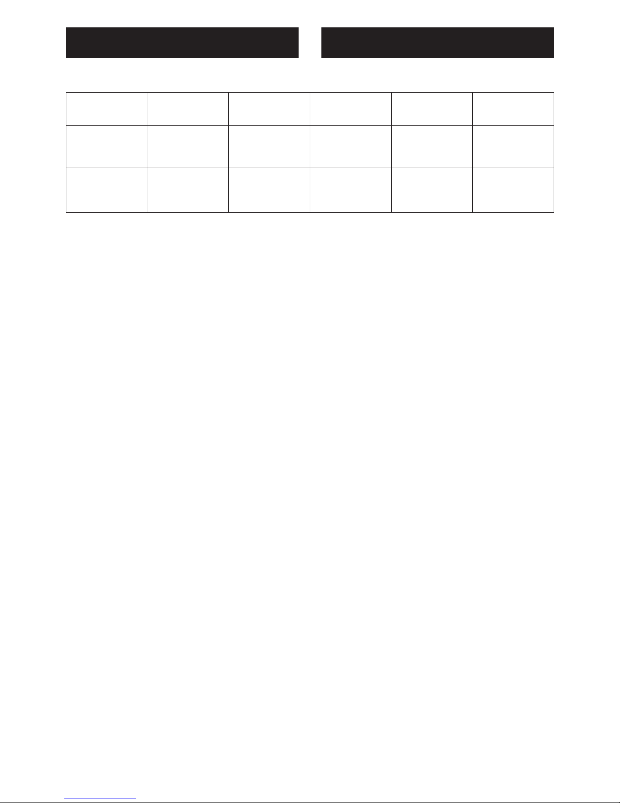
GAS Burner Injector Consumption low flow-rate
nominal flow-rate
(kW) (kW)
G20 auxiliary 76 95 l/h 0,45 1,00
20 semi-rapid 94 157 l/h 0,60 1,65
mbar rapid 128 276 l/h 0,95 2,90
G30/G31 auxiliary 50 73 g/h 0,45 1,00
28-30 mbar semi-rapid 65 120 g/h 0,60 1,65
37 mbar rapid 85 211 g/h 0,95 2,90
GAS BURNERS CHARACTERISTICS
Page 5

4'x7'x7'6" high). If it is installed in a room of volume between 6m3 and 9m3 an air vent of effective areas 65m2 is required. If it is installed in a
room of volume between 9m3 and 11m3 an air
vent of effective areas 35cm2 is required, while if
the room volume exceeds 11m3 no air vent is required. However, if the room has a door that
opens directly to the outside, no air vent is required even when the room volume is between
6m3 and 11m3.
The above requirements allow also for the use of
a gas oven and grill but, if there are other fuel
burning appliances in the same room, BS5400
1976 should be consulted to determine the required air vent requirements.
If the appliance is installed in a cellar or basement, it is necessary to provide an air vent of effective area 65m2 irrespective of the room volume.
The use of a gas appliance results in production
of heat and moisture in the room in which it is installed. Ensure that the kitchen is well ventilated,
keep natural ventilation holes open or install a
mechanical ventilation device (mechanical extraction hood).
Prolonged intensive use of the appliance may call
for additional ventilation, for example increasing
the level of mechanical ventilation where present.
UNPACKING YOUR HOB
Once the packaging has been removed, thoroughly check that the appliance is in perfect condition.
If you have any doubts do not use the appliance
and call Comet Service Centre on 0870 5425425.
Some parts mounted on the appliance are protected by a plastic film. This protection must be
removed before using the appliance. We recommend slitting the plastic film along the edges with
a sharp knife or pin.
Position
To fit the hob into the unit make an opening of the
dimensions given in fig 2 remembering that:
• Inside the unit there must be a space of at least
30mm between the bottom of the hob and the
top of a shelf.
• Any wall to the side of the hob must be at least
100mm away (fig 2).
• The wall behind the hob must be at least 58mm
away (fig 2).
• When there is a wall unit or hood above the hob
there must be at least 750mm between the hob
and the unit or hood.
• If the hob is not installed over a built in oven, it
is essential to install a heat baffle between the
bottom of the hob and the underlying unit.
• If the hob is installed over a built in oven, there
must be a distance of at least 30mm between
the two appliances. The two appliances should
be connected to the gas supply with independent connections, in compliance with the current
laws in force.
Fixing
A self adhesive seal (A fig 3) is supplied with the
hob. This must be placed under the edge of the
hob top, as close as possible to the edge (fig 3).
The seal must run all round the unit to ensure a
perfect seal and prevent moisture from seeping
under the hob.
Place the hob in the hole in the worktop, making
sure that there is a good seal between the edge
of the hob and the worktop (fig 4).
Secure the hob to the worktop using the brackets
(C fig 5) and screws supplied, do not over tighten
the screws.
GAS CONNECTION
Important
This appliance is supplied for use on NATURAL
GAS ONLY and cannot be used for any other gas
without modification. This appliance is supplied
with a replacement set of injectors for use with
LPG, but conversion for use on other gases must
only be undertaken by a C.O.R.G.I. registered installer. For information for use on other gases
contact your local Comet Service Centre.
Note: The installation of the hob to Natural gas or
LP Gas must be carried out by a C.O.R.G.I. registered installer. Installers shall take account of
the provisions of the relevant British Standards
Code of Practice, the Gas Safety Regulations
and the Building Standards (Scotland) (Consolidation) Regulations issued by the Scottish Development Department.
The appliance complies with the provisions of the
following EEC Directives:
90/396 + 93/68 regarding gas safety.
The minimum distance from hob top to an overhanging cupboard or hood must be at least
750mm.
The hob is supplied with an elbow connection
(fig 6) and is adjusted to work with mains gas.
Installation to Natural Gas
Installation to Natural Gas must conform to the
Code of Practice etc. The supply pressure for
Installation
4
Page 6

Natural Gas is 20 mbar (8 inch W.G.).
Installation to LP Gas
This appliance must only be connected to LPG
after an LPG conversion kit has been fitted (see
section conversion to LPG). When operating on
Butane gas a supply pressure of 28 mbar (11
inch W.G.) is required. When operating on
Propane gas a supply pressure of 37 mbar (14
inch W.G.) is required. The installation must conform to the relevant British Standards.
Warning: Only a C.O.R.G.I. registered installer,
also with technical knowledge of electricity
should install gas hobs. They should observe the
Regulations and Codes of Practice governing
such installation of gas hobs.
Important: After installation check that all
connections are airtight.
CONVERSION TO LP GAS
Warning: Replacement of injectors must only be
undertaken by a qualified gas engineer and when
changing injectors to a different type of gas supply the instructions on adjustment and installation
on the particular category of gas supply must be
observed.
After conversion always carry out a gas leak test.
REPLACING INJECTORS (FIG. 7)
To replace the injectors proceed as follows: The
hob is preset with natural gas. The appliance is
preset with the injectors necessary for adaptation
to bottled gas (butane or propane), comprising a
hose connection.
If the hob has to be changed from natural gas,
proceed as follows:
- Remove the pan supports, the burner caps (A),
and the burners (B);
- Unscrew and remove the injector in the bottom
of each injector holder (C);
- replace the injector in accordance with the table
in page 3, tighten and screw right down;
- check that the system is gas-tight;
- replace the burners, the burner caps and the
pan supports.
IMPORTANT:
- Never over-tighten the injectors;
- after replacing, check that all the injectors are
airtight.
SETTING HOB BURNER MINIMUM LEVELS
If the hob is to work on bottled gas (butane/
propane), the tap by-pass must be screwed right
down. The hob may be equipped with type A
taps, with by-pass inside (accessed by inserting
a small screwdriver into the rod) or type B taps,
with by-pass on the outside on the right (accessed directly). See figure 8.
If the hob is to work on natural gas, proceed as
follows for both types of tap:
- Ignite the burner at maximum flame;
- pull off the knob, without using a lever against
the control panel, which might be damaged;
- access the by-pass with a small screwdriver
and back off by about 3 turns (turning the
screwdriver anti-clockwise);
- turn the tap rod anti-clockwise again until it
stops: the burner will be at maximum flame;
- screw the by-pass slowly back in, without pushing the screw-driver, until the flame has apparently shrunk to 1/4 of the maximum size, checking that it is sufficiently stable even in quite
strong draughts.
ELECTRICAL CONNECTION
For your safety please read the following information
Warning: This appliance must be earthed.
The appliance must be connected to a 220-240
volts 50 cycle AC supply by means of a three pin
socket, suitably earthed and should be protected
by a 3 amp fuse in the plug or a15 amp fuse in
the consumer unit.
The appliance is supplied with a rewireable 13
amp 3 pin plug fitted with a 3amp fuse. Should
the fuse require replacement, it must be replaced
with a fuse rated at 3 amp and approved to
BS1362.
If the mains plug is unsuitable for the socket outlet in your home or is removed for any other reason, then the cut off plug should be disposed of
safely to prevent the hazard of electric shock.
There is a danger of electric shock if the cut off
plug is inserted into any 13 amp socket outlet.
How to wire a 3 amp plug
5
Installation
Page 7

6
Important
The wires in the mains lead on this appliance are
coloured in accordance with the following code:
Green and Yellow - Earth
Blue – Neutral
Brown – Live
As the colours may not correspond with the
markings identifying the terminals in your plug
proceed as follows.
The green and yellow wire must be connected to
the terminal in the plug which is marked with the
letter E or with the earth symbol or coloured
green and yellow.
The blue wire must be connected to the terminal
marked N or coloured black.
The brown wire must be connected to the terminal marked L or coloured red.
IMPORTANT: the manufacturer declines all liability for damage due to failure to comply with the
regulations and standards in force.
ELECTRIC IGNITION
The correct gap between the electrode and the
burner is shown in figure 9.
If no spark is generated, do not keep on trying as
this might damage the generator.
Possible causes of malfunctions:
- spark plug damp, dirty or broken;
- electrode-burner gap not correct;
- spark plug wire broken or without sheathing;
- spark discharging to earth (to other parts of the
hob);
- generator or microswitch damaged;
- air has built up in the pipes (particularly if the
hob has been out of use for a long time);
- air-gas mixture incorrect.
HOW TO USE THE HOB
VENTILATION
All gas cooking appliances produce heat and
moisture in the rooms where they are installed.
Ta ke care to ensure that the kitchen is well ventilated; keep the ventilation openings unobstructed
or install an extractor hood with fan.
In case of intensive or prolonged use, additional
ventilation may be required; open a window, or increase the extractor fan power.
IGNITING THE HOB BURNERS
- Press the knob and turn it anti-clockwise until it
reaches the symbol on the control panel
(maximum flame position);
- at the same time, press and hold the ignition
button until the burner lights;
- to reduce the flame, turn the knob further in the
same direction until its pointer is against the
symbol (minimum flame position).
IMPORTANT
- Difficulty in igniting burners is normal if the hob
has been out of use for some time. The air accumulated in the pipes will be expelled in a few seconds;
- Never allow too much unburnt gas to flow from
the burners. If ignition is not achieved within a relatively short time, repeat the procedure after returning the knob to the off position (•);
HOW TO USE THE HOB BURNERS
Use pans of diameter suitable for the burner type.
The flames must not project beyond the base of
the pan. Recommended sizes:
- for auxiliary burners = pans of at least 8 cm
- for semi-rapid burners = pans of at least 14 cm
- for rapid burners = pans of at least 22 cm.
N.B.: Never keep the knob at settings between
the maximum flame symbol and the off position ( •).
CLEANING AND MAINTENANCE
General tips
• Before cleaning the hob switch it off and wait for
it to cool down.
• Clean with a cloth, hot water and soap or liquid
detergent.
• Do not use products which are abrasive, corrosive or chlorine based.
• Do not use steel pads.
• Do not leave vinegar, coffee, milk, salty water or
juice of lemon or tomato on the hob surface for
any length of time.
Installation For the user
Page 8

Enamelled parts
All enamelled parts must be washed only with a
sponge and warm soapy water or other non abrasive products. Dry carefully.
Stainless steel parts
Clean with special products for stainless steel
which are available on the market. Dry preferably
using a chamois leather.
Note: Regular use will cause discolouring around
the burners, this is due to the high temperature of
the flame
Burners and pan supports
These pieces can be removed and washed with
a sponge and warm soapy water or other non
abrasive products. After cleaning dry them well
and replace them correctly. Keep the electrodes
clean so that the sparks always strike.
Note: To avoid damage to the electric ignition do
not use it when the burners are not in place.
Control knobs
The control knobs can be removed for cleaning
by just pulling.
Gas taps
Regular lubrication of the gas taps must only be
performed by qualified engineers.
If the gas taps are not working properly contact
your nearest Comet Service Centre on 0870
5425425.
INFORMATION AND SERVICE
For any information you require about the product
contact the Proline helpline on 0113 2793520
If you require a service call contact your nearest
Comet Service Centre on 0870 5425425.
The manufacturer declines all responsability for
injury or damage deriving from poor installation
or incorrect use of the hob.
For the user
7
Page 9

8
Figure
A = AUXILIARY
SR = SEMIRAPID
R = RAPID
1
2
3
4
Page 10

9
Figure
9
5
6
7
8
Page 11

Page 12

Page 13

ED. 12/09/2003 334995
 Loading...