

Page 1
PROline
Model TCE5
BUILT-IN ELECTRIC HOB
INSTRUCTION BOOK
Page 2

Operating and Installation Instructions
GB
Page 3

Technical data and specifications . . . . . . 3
Installation . . . . . . . . . . . . . . . . . . . . . . . 3
Electrical connection. . . . . . . . . . . . . . . . 4
For the user. . . . . . . . . . . . . . . . . . . . . 4-5
Cleaning and maintenance . . . . . . . . . . . 5
Figures . . . . . . . . . . . . . . . . . . . . . . . . 6-7
Important notes and precautions for use
Dear User,
We would ask that you read carefully the instructions contained in this booklet.
It provides information for a safe installation, use
and maintenance. Keep this booklet in a safe
place for future reference.
The installation and maintenance operations listed must only be carried out by qualified personnel.
The appliance must only be used for its original
purpose, that is, cooking for domestic use.
Any other use is considered improper and as
such dangerous.
The manufacturer cannot be held responsible for
any damage to persons or property resulting
from an incorrect installation, maintenance or use
of the appliance.
The manufacturer disclaims all responsibility if
these instructions are not following.
The appliance was designed and made in accordance with the following European Standards:
- EEC 90/396
- EEC 73/23 and 93/98
- EEC 89/336 (radio-frequency interference)
- EEC 89/109 (contact with foods)
Index Introduction
2
Page 4

Technical data and specifications
Installation
ELECTRIC HOTPLATES
ø 145 mm 1,0 kW - Normal hotplate
1,5 kW - Rapid hotplate
ø 180 mm 1,5 kW - Normal hotplate
2,0 kW - Rapid hotplate
Cat.: see nameplate on cover; Class 3
Type “X” hobs
EQUIPMENT
For the LAYOUT OF HOTPLATES see the models illustrated in figure 1 at the back of this manual.
For the ELECTRIC WIRING DIAGRAM see figure 2 at the back of this manual.
The electrical power is indicated on the nameplate underneath the hob.
A copy of the nameplate is glued to the cover of
this manual.
INSTALLATION
The hob must be installed by a qualified electrician in line with all electrical and installation requirements published by the institute of Electrical
Engineers.
UNPACKING YOUR HOB
Once the packaging has been removed, thoroughly check that the appliance is in perfect condition.
If you have any doubts do not use the appliance
and call Comet Service Centre on 0870
5425425.
Some parts mounted on the appliance are protected by a plastic film. This protection must be
removed before using the appliance. We recommend slitting the plastic film along the edges with
a sharp knife or pin.
Position
To fit the hob into the unit make an opening of the
dimensions given in fig 3 remembering that:
• Inside the unit there must be a space of at least
30mm between the bottom of the hob and the
top of a shelf.
• Any wall to the side of the hob must be at least
100mm away (fig 3).
• The wall behind the hob must be at least 58mm
away (fig 3).
• When there is a wall unit or hood above the hob
there must be at least 650mm between the hob
and the unit or hood.
• If the hob is not installed over a built in oven, it
is essential to install a heat baffle between the
bottom of the hob and the underlying unit.
• If the hob is installed over a built in oven, there
must be a distance of at least 30mm between
the two appliances.
Fixing
A self adhesive seal (A fig 4) is supplied with the
hob. This must be placed under the edge of the
hob top, as close as possible to the edge (fig 4).
The seal must run all round the unit to ensure a
perfect seal and prevent moisture from seeping
under the hob.
Place the hob in the hole in the worktop, making
sure that there is a good seal between the edge
of the hob and the worktop ( fig 5).
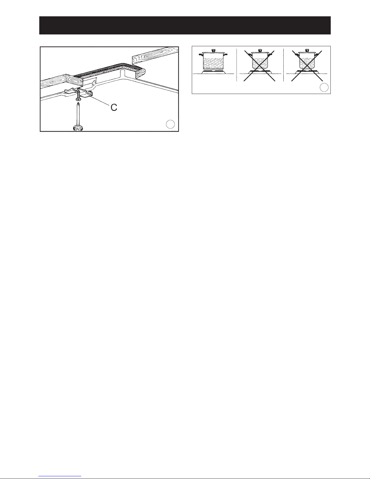
Secure the hob to the worktop using the brackets
(C fig 6) and screws supplied, do not over tighten
the screws.
3
Page 5

ELECTRICAL CONNECTION
For your safety please read the following information
Warning: This appliance must be earthed.
Your hob must be connect to the mains supply by
a qualified electrician.
To connect the mains cable to the hob it is necessary to carry out the following operations:
• Unscrew the small cover plate on the base of
the hob.
• Ensure the links are fitted into the mains terminal block as shown in (fig 2).
• Insert the mains cable type 3x2.5mm2 through
the hole in the base plate.
• Connect the wires to the terminal block as
shown in (fig 2).
• Secure the mains cable with the cable clamp.
• Refit the cover plate.
Important
This appliance requires a 30 amp supply.
A double pole switch must be provided no further
than 2 metres from the appliance to the electrical
supply.
All supply current and earth conductors must be
able to withstand an ambient of 750C.
The appliance must be connected using 3x2.5
mm2 cable (not supplied).
Note: This appliance is intended to be permanently connected to fixed wiring.
If you are using the hob for the first time or after
a period where the hob as not been in use, you
should set the controls to position 1 for approximately 30 seconds to dry out any humidity.
IMPORTANT: the manufacturer declines all liability for damage due to failure to comply with the
regulations and standards in force.
HOW TO USE THE HOB
The different heat settings are obtained as
follows:
- 1 = minimum setting;
- 6 = maximum setting;
- 0 = off.
Pans must never be smaller in diameter than the
hotplates and their bottoms must be as flat as
possible (see fig. 7).
IMPORTANT:
- Never leave hotplates on without pans, except
when first used; leave for about 10 minutes to
dry oil or moisture residues;
- if the hotplate is to be out of use for a long time,
apply a little grease to its painted surface;
- do not allow spills to burn onto the hotplate, requiring the use of abrasive cleaners.
For economical cooking:
- Use pans with flat bottoms which are in contact
with the hotplate in all points:
• in stainless steel with thick or sandwich bottom;
• in aluminium with thick, flat bottom;
• in enamelled steel;
- make sure that pans are of appropriate size; the
pan bottom diameter must be equal to or larger
than that of the hotplate used;
- switch the hotplate off a few minutes before the
dish is completely cooked;
- use a lid whenever possible to prevent losses by
evaporation;
- never supply more power than the food is able
to absorb; excess heat leads to losses of water
and fats and wasted energy;
- never use more water than necessary.
The table below will serve as a guide, bearing in
mind that cooking times and temperatures may
vary depending on the type and amount of foods
cooked and personal taste.
Installation For the user
4
Knob Heat Cooking
setting intensity process
0OFF 1WEAK Keeping foods warm,
bechamel sauce, custard
2 LOW Reheating foods
3 MEDIUM Pasta, vegetable soups,
ragout
4 MEDIUM Boiling, roasting
/HIGH
5 HIGH Steamed vegetables,
steaks, fish
6 VERY Grilling, omelettes, lamb
HIGH chops
Page 6

CLEANING AND MAINTENANCE
General tips
• Before cleaning the hob switch it off and wait for
it to cool down.
• Clean with a cloth, hot water and soap or liquid
detergent.
• Do not use products which are abrasive, corrosive or chlorine based.
• Do not use steel pads.
• Do not leave vinegar, coffee, milk, salty water or
juice of lemon or tomato on the hob surface for
any length of time.
Warning
After use to keep the electric plates in good condition and prevent rusting apply a small drop of
cooking oil onto the plates.
If any liquid spills over it must always be removed
with a sponge.
Enamelled parts
All enamelled parts must be washed only with a
sponge and warm soapy water or other non
abrasive products. Dry carefully.
Stainless steel parts
Clean with special products for stainless steel
which are available on the market. Dry preferably
using a chamois leather.
Note: Regular use will cause discolouring around
the burners, this is due to the high temperature of
the flame
Control knobs
The control knobs can be removed for cleaning
by just pulling.
INFORMATION AND SERVICE
For any information you require about the product
contact the Proline helpline on 0113 2793520
If you require a service call contact your nearest
Comet Service Centre on 0870 5425425.
The manufacturer declines all responsibility for
injury or damage deriving from poor installation
or incorrect use of the hob.
For the user
5
Page 7

Figure
6
P1 = hotplate Ø 180
P2 = hotplate Ø 145
P2
P1
P1
P2
1
CONNECTION DIAGRAM
230 V TWO-PHASE
Wire gauge
2
3
4
5
Page 8
Figure
7
7
6
Page 9

ED. 06/03/2003 334996
 Loading...