

Page 1
PGH460GL-EU
ORERATING AND INSTALLATION
INSTRUCTIONS
BUILT-IN GAS HOB
Page 2

CONTENTS
1. DESCRIPTION OF THE HOB
2. SAFETY INSTRUCTIONS
3. INSTALLATION
4. USAGE
5. MAINTENANCE & CARE
Page 3

Dear Customer,
Thank you for purchasing this Proline Cooking Hob. The safety precautions and
recommendations in these instructions are for your own safety and that of
others. They will also provide a means by which to make full use of the features
offered by your appliance.
Please keep this booklet in a safe place. It may be useful in future, either to
yourself or to others in the event that doubts should arise relating to its
operation.
This appliance must be used only for its intended purpose, that is for the
domestic cooking of foodstuffs. Any other form of usage is to be considered as
inappropriate and therefore dangerous.
The manufacturer declines all responsibility in the event of
damage caused by improper or incorrect use of the appliance.
CE Declaration of conformity
• This cooking hob has been designed to be used only for cooking. Any other
use (such as heating a room) is improper and dangerous.
• This cooking hob has been designed, constructed, and marketed incompliance
with:
- Safety requirements of the "Gas" Directive 90/396/EC;
- Safety requirements of the
"Low voltage" Directive 2006/95/EC;
- Safety requirements of the “EMC” Directive 89/336/EC;
- Requirements of the Directive 93/68/EC.
GB
1
Page 4
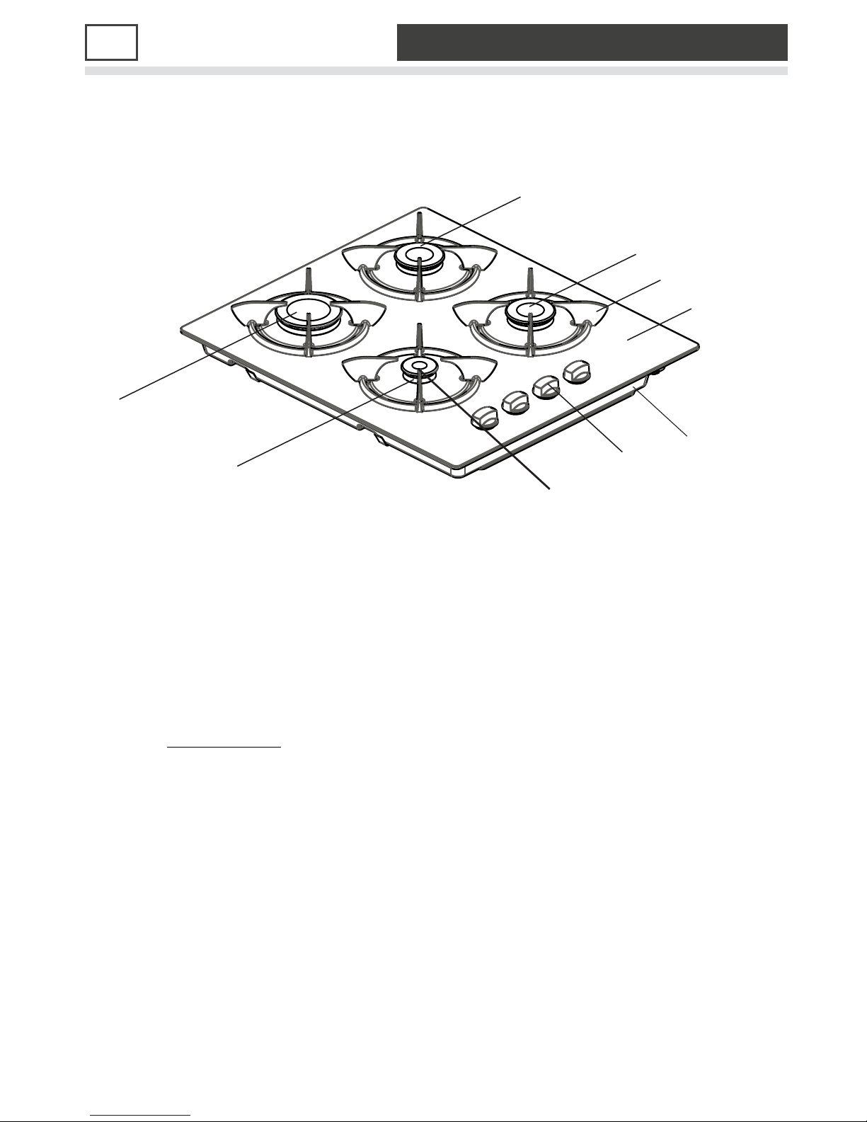
1 DESCRIPTION OF THE HOB
3
2
1
6
7
4
Descriptions:
1. Ceramic glass
2. Pan support
3. Burner cap
4. Burner body
5. Control knob
5
8
6. Rapid burner
7. Semi-rapid burner
8. Auxillary burner
9. Base cover
2
Page 5

SAFETY INSTRUCTIONS2
READ ALL IMPORTANT SAFEGUARDS AND ALL INSTRUCTIONS
BEFORE USING THE APPLIANCE
The adjustment conditions for this appliance are stated on the rating label. This
appliance shall be installed in accorance whit the regulations in force and only used
in a well ventilated space. Read the instructions before using or installing this
appliance. Appliances should be electrically Problems due to to improper
connection are not covered by the warranty.
This appliance is not connected to a combustion product evacuation device.
Particular attention shall be given to the relevant requerements regarding
ventilation.
The use of a gas cooking appliance results in heat and moisture in the room in
which it is installed. Ensure that the kitchen is well ventilated. Keep natural
ventilation holes open or install a mechanical ventilation devicen (mechanical
cooker hood). Prolonged intensive use of the the appliance may call for additional
ventilation, for example increasing the level of mechanical ventilation, where
present.
While operating this appliance needs 2m3/hr air per kW heat input.
earthed.
In the event of the burner flames being accidentally extinguished, turn off the
burner control and do not attempt to re-ignite the burner for at least one moment.
Remove all the tape and packaging wrap before using the appliance. Do not
store any pressurised containers, such as aeresol cans, flammable materials,
including paper, plastic and cloth items, in the drawer, near the surface.
Do not attempt for gas leakage with a flame.
All the operations including installation, fine tuning, transformations and the
servicing operations must be carried out exclusively by qualified personnel.
3
Page 6
3 INSTALLATION
PRIOR TO INSTALLATION, ENSURE THAT THE LOCAL
DISTRIBUTION CONDITIONS AND THE ADJUSTMENT
OF THE APPLIANCE ARE COMPATIBLE.
This appliance must be installed by a qualified gas installer who must also
be a qualified electrician if the appliance requires connecting to a mains
electricity supply.
After removing the packaging material from the appliance and its accesories
ensure that the hob is not damaged. If you suspect any damage do not use the
appliance and contact a qualified technician immediately.
This built-in hob is to be inserted into a cut out of a worktop. It will be electrically
connected with the mains socket below counter level especially provided for this
purpose. In all oher respects, the user of the appliance is also liable for the orderly
installation and operation - in confirmity with these instructions - according to the
Appliances Safety LawAnd The Applicable Regulations and Prescriptions.
s
Locating Your Built-in Hob
The Hob is supplied with a special seal in order to avoid any liquid infiltration in
the work top. Cut out an opening in the top of your kitchen unit that corresponds to
the measurements given in figure. Apply the self adhesive seal to all edges of the
and carefully fit the hob into the opening in such a way that the knobs will be right
side.
The leaf springs located on the lower left and right sides of the hob will fix the hob
in the opening.
4
Page 7

Create a space to install your hob , following the dimensions indicated on figure.
•
100 mm from edge of cooker to combustible materials.
•
0 mm underside of overhead cupboards, shelving
70
•
750mm underside of overhead exhaust fans.
This appliance must be installed according to the manufacturers installation
instructions, local building regulations, gas authority codes and electrical wiring
instructions.
.
Changing the Gas Inlet
The gas feeding manifold protruding from the back of the hob must be visible
completely, any means connection (nut,hose etc.)must be placed with attention to
avoid any contact with parts that will heat up. It is highly recommended to block the
access to pipe connection, while the is in use or when the gas supply is open.
During the gas connection process, the pipe of the appliance should be kept
stationary, while the connected part (mechanical, LPG or NG nut) is fixed.Always
use the seals supplied in the spare set between the connection ‘A’ for flexible hose
connection.
For connection of methane type gases (NG),
•
Use B type connection in Spain, Italy, Portugal, Greece, France and Algeria for
use with flexible hose conection.
o
•
Use C type connection in Letonia and Luxemburg for mechanical connection.
This connection may also be optionally used in some areas in France, Algeria,
o
Spain, Portugal and Italy.
o
•
Use C type connection in Germany and Belgium with an additional
o
ISO7/ISO228 adapter and Netherlands with an additional Besca adapter,
o
supplied in the spare set. An example of usage is shown in E.
hob
:
5
Page 8

•
For all types of gas D type connection in United Kingdom and Ireland,
the flexible gas hose should neither pass behind an n be in contact with
o
objects that
o
I
MPORTANT
•
The appliance should be installed, regulated and adapted to function ther
types of gas by a QUALIFIED INSTALLATION ENGINEER.
o
•
Failure to comply with this condition will render the guarantee invalid
•
The appliance must be installed by a gas installer who appears on the gas register.
•
The appliance must be installed in compliance with regulations in force.
•
Installation engineers must comply to current laws in force concerning
ventilation and evacuation of exhaust gases.
o
•
Always unplug the appliance before carrying out any maintenance or repairs
•
Minimum distance between the appliance and combustible premises must be
20 mm
o
•
After the connection had been it has to be tested.
•
This test can be done by applying a soapy liquid to the connection. No bubble
should appear. If there are bubbles, check the connection joint and recheck it if
o
necassary.
o
•
For all gas connections, make sure that the connection parts and gas delivery
components are in accordance with local and international requirements.
o
may cause combustion.
using the
oven or
with o
.
.
made,
.
DO NOT USE NAKED FLAME TO CHECK FOR GAS LEAKS
6
Page 9

Table for the choice of the injectors
Gas Category
RAPID BURNER
Injec tor diam.(%mm)
NominalRating (kw)
Min.Rating(k w)
Consumptionin1h
Consumption in 1h
(at150C and 1013mbarpress)
AUXILL ARY BURNER
Injector diam.(%mm)
Nom inalRating (kw)
Min.Rating (kw)
Consumptionin1h
Consumptionin1h
(at150C and 1013mbarpress)
MEDIUM BURNER
Injector diam.(%mm)
Nom inalRating (kw)
28-30 m bar
85
3
0.85
218.13 gr/h
50
1
0.4
72.71 gr/h
65
1.75
LPG
G31
28-30/37 m bar
85
3
0.85
214.28gr/h
50
1
0.4
71.42gr/h
65
1.75
G30
50 mbar
75
3
1.23
218.13gr/h
43
1
0.5
72.71 gr/h
58
1.75
NG
G20
20 mbar
115
3
0.7
285.7lt/h
72
1
0.3
95.24 lt/h
97
1.75
G25G3 0
25 mbar
125
3
0.82
332.2 lt/h
72
1
0.3
110.74 lt/h
94
1.75
Min.Rating(k w)
Consumption in 1h
Consumptionin1h
(at150Cand 1013mbarpress)
127.25 gr/h
0.65
0.65
125gr/h
0.65
127.25gr/h
0.495
166.66 lt/h
0.495
193.79lt/h
7
Page 10

LOCATION
The appliance may be installed in a kitchen, kitchen/diner or a bed sitting room, but
not in a room or space containing a bath or a shower.
The appliance must not be installed in a bed-sitting room of less than 20 m .
The appliance is designed and approved for domestic use only and should not be
installed in a commercial, semi commercial or communal environment. Your
product will not be guaranteed if installed in any of the above environments and
could affect any third party or public liability insurances you may have.
3
VENTILATION REQUIREMENTS
İ
The appliance should be installed into a room or space ith an air
supply in accordance with BS 5440-2:2000.
For rooms with a volume of less than 5 m - permanent ventilation of 100 mm free
area
will be required.
For rooms with a volume of between 5 m and 10 m a permanent ventilation of 50
2
cm
free area will be required unless the room has a door which opens directly to the
3
33
2
outside air in which case no permanent ventilation is required.
For rooms with a volume greater than 10 m - no permanent ventilation is required.
3
NB. Regardless of room size, all rooms containing the appliance must have direct
access to the outside air via an openable window or equivalent.
Where there are other fuel burning appliances in the same room, BS 5440 2:2000
should be consulted to determine the correct amount of free area ventilation
requirements.
The above requirements allow use of a gas oven and grill but if there are other
gas burning appliances in the same room, consult a qualified engineer.
6
Page 11
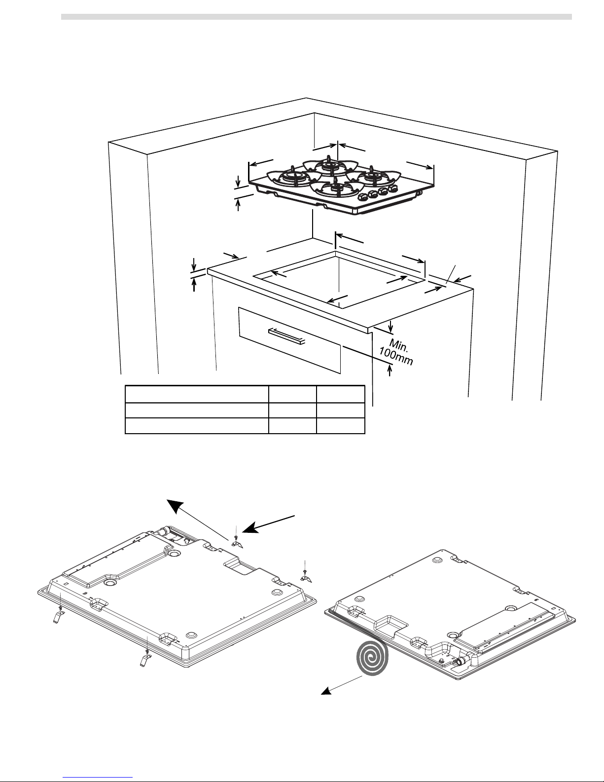
Locating the built-in hob
43.5mm
Min.
25mm
Neigboorhood walls
Combustible
Non-combustible
523mm
Min. B
A [mm] B [mm]
60 150
40 50
594mm
560mm
Min. A
490mm
Page 12

ELECTRICAL CONNECTION
Before proceeding with the electrical connection verify that :
•
The current carrying capacity of the system and the socket is adequate for the
o
maximum power rating of the hob.
•
The voltage indicated on the capacity label is the same as the supply voltage
•
Do not use for connection any reductions , adapters or shunts because they may
o
cause overheating.
•
The socket has an earth terminal.
BROWN
BLUE
N
L
YELLOW+GREEN
Please ensure that the voltage on the capacity label is the same as the supply
voltage before connection is made.
The appliance is provided with supply cord and a plug. Replacement of the mains
cable must be . Unplug your appliance
carried out by a
before each maintenance. Follow reconnection diagrams strictly. The protective
earth connection (PE) must be connected to the Terminal marked ( ). During
installation, please ensure that isolated cables are used.
9
Page 13

ELECTRICAL CONNECTION (UK ONLY)
For your safety please read the following information
Warning: This appliance must be earthed.
The app liance must be connected to a 240 volts 50 cycle AC supply by
means of a three pin socket, suitably earthed and should be protected by
a 3 amp fuse in the plug.
The appliance is supplied with a 1 3-amp 3-pin mains plug fitted with a 3
amp fuse. Should the fuse require replacement, it must be replaced with a
fuse rated at 3 amp and approved to BS1362
The plug contains a removable fuse cover that must be refitted when th e
fuse is replaced. In the event of the fuse cover being lost or damaged, the
plug must not be used until a replacement cover has been obtained.
If the mains plug is unsuitable for the socket outlet in your home or is
removed for any other reason, then the fuse should be removed and the
cut off plug disposed of safely to prevent the hazard of electric shock.
There is a dan ger of electric shock if the cut off
plug is inserted into any 13 amp socket outlet.
How to wire a 13 amp plug Important
FUSE
The wires in the mains lead on this appliance are
3 Amps
coloured in accordance with the following code :
Green and Ye llow – Earth
Blue – Neutral
Brown – Live
As the colours may not correspond with the markings identifying the terminals
in your plug proceed as follows.
The green and yellow wire must be connected to the terminal in the plug,
which is marked with the letter E, or with the earth symbol or coloured green
and yellow.;
The blue wire must be connected to the terminal marked N.
The brown wire must be connected to the terminal marked L.
10
Page 14

4
USAGE
4.1 Usage of Your Gas Burners
Manual Ignition
To ignite one of the burners, approach a match to its upper circumference and
push the corresponding conrol knob and turn it counter clock-wise. Medium
regulation of the flame will be obtained by turning the control knob between
maximum position (big flame) and the minimum position (small flame).
The small diagrams situated on the control panel indicate to the gas burners in
use.
Ignition Through Control Knob (microswitch):
Press the hob valve you want to operate and turn the control knob in the counterclockwise direction. The microswitch placed under the knob will automatically
create sparks through the spark plug of the burner. Continue pressing the knob
until you see a stable flame on the burner.
Recommandations:
Your hob is composed with of burners different diameters. The most economic
way of using gas is too choose the correspanding gas burners for your cooking
pan size and to bring the flame to minimum position once the boiling point is
reached. It is recomended to always cover your cooking pan.
In order to obtain maximum performance from the burners, use pots with the
following flat bottom diameters.
Rapid Burner : 22-26 cm
Medium Rapid Burner : 14-22 cm
Auxillary Burner : 10-18 cm
11
Page 15

GAS CONVERSIONS
Transformation For The Gas Cookers Replacement Of Injectors
GAS CONNECTION
The installation of the gas appliance to natural gas or LPG
must be carried out by a gas safe registered engineer.
Engineers shall take due account of the provisions of the
relevant British
regulations and the building standards (Scotland)
(Consolidation) regulations issued by the Scottish
development department.
The gas burners adapt to different types of gas, by replacing
the corresponding injectors to gas on use.
There fore it is necassery to;
•
Cut off the feeding gas flow and electric current.
•
Remove the cap and the adapter.
•
Unscrew the injectors.
•
Replace the injector with the ones corresponding to the type of gas that is
o
going to be used, according to the information on the transformation chart.
Standards Code of practice, the gas safety
INJECTORS REPLACEMENT OF HOB BURNERS
I
This appliance is manufactured for conversion to LPG. To purchase an LPG
conversion kit, contact the store where you purchased this appliance. The
diameter is marked on the injector in cents of millimetre.
Select the injectors to be replaced according to the "Table for the choice of the
injectors". To replace the injectors: Remove pan-supports and burners from the
hob top. sing a spanner, remove the injector from its housing and replace it by
the proper one according to the kind of gas (see “Table for the choice of the
injectors").
U
the
Adjusting The Reduced Flame Position
For reduced flame position the by pass screw must be loosened in
transformation from LPG to NG. In transformation from NG to LPG, the same
screw must be
•
Make sure that the appliance is unpluged from the electric current and the gas
o
feed is open.
•
Ignite the burners and leave them on in minimum position.
•
Remove the knobs and rubber seals because the screws are accesible only
when the knobs and the seals are removed.
o
•
This procedure must be for each of the valves.
tightened.
repeated
12
Page 16

•
With the help of a small screwdriver fasten or loosen the by pass screw by 90°,
o
which makes the flame of the burner reduce to the minimum.
When the flame has a length of at least 4 mm, the gas is well distributed.
Make sure that the flame does not die out when passing from the maximum
position to the minimum position.
After the adjustment is complate replace the rubber seal and replace the knob.
13
Page 17

5
MAINTENANCE & CARE
Disconnecting:
Before cleaning disconnect the hob from the electricity supply
gas supply.
by closing the main
Burner Caps:
Periodically, enamelled pan supports, enamelled covers, burner heads must be
washed with soapy warm water rinsed and dried.
After drying them thoroughly, replace them correctly in their placement.
Pan Supports:
In order to keep them a new, it is necessary to clean them frequently with mildly
warm soapy water and then dry with a soft tissue. Do not wash them while hot
and never use abrasive powders or abrasive cleaning materials. Do not leave
vinegar, coffee, milk, salt, water, lemon, or tomato juice to remain in contact with
enamelled parts for long periods of time.
CLEANING THE CERAMIC GLASS SURFACE
•
Before you begin cleaning make, sure the appliance is switched off and cooled
o
down
•
Remove spillages and incrustations with a scraper (
o
separately contact the store where you purchased this appliance
•
Dust or food particles can be removed with a dampened cloth.
•
Clean the glass surface with warm water and mild detergent, do not use
o
aggressive or abrasive cleaners, as they will damage the surface.
•
All traces of the cleaner MUST be removed with a damp cloth and then a dry
o
one.
•
Boiled over Fat and Liquids from food must be removed immediately to avoid
o
damage to the surface. If they are allowed to harden they become increasingly
o
difficult to remove. This is especially true in the case of ugar, yrup mixtures
o
that could permanently pit the surface of the appliance if left to burn on. If
o
Plastic, sugar, syrup or similar substance, has melted onto the appliance
o
surface, it must be removed with a scraper immediately (whilst the surface is
o
still hot) to avoid permanent damage.
•
Do not use knives, steel wool or abrasive sponges to clean the appliance, as
o
these products will result in damage to the surface.
•
Remove the control knobs to clean in warm soapy water, take care not to
o
damage the seals underneath the control knobs.
•
DO NOT use a steam cleaner as water ingress will result in internal damage
o
voiding the warranty.
Scraper available
).
ss
14
Page 18

If something do
esn't seem to work
If there is something about your appliance which you do not understand
and you live in the UK you can phone our help line during normal office
hours on: 0844 8009595 If you require s
sales receipt.
Calls are charged at standard rates.
We
apologise for any inconvenience caused by minor inconsistencies
in these instructions, which may occur as a result of product improvement
and development.
ervice, call the number on your
Kesa U.K HU1 3AU 01/06/2010
Page 19

PGH465GM-N
BEDIENING EN INSTALLATIE
INSTRUCTIES INGEBOUWDE
GAS.22.3/$A7
Page 20

INHOUD
1. BESCHRIJVING VAN DE KOOKPLAAT
2. VEILIGHEIDSINSTRUCTIES
3. INSTALLATIE
4. HET IN GEBRUIK NEMEN VAN DE KOOKPLAAT
5. ONDERHOUD AAN HET APPARAAT
Page 21

Beste klant,
Dank u voor uw aankoop van een Proline gaskookplaat. De veiligheidsmaatregelen
en aanbevelingen in deze instructies gelden voor uw veiligheid en die van
anderen. Ze bieden ook een mogelijkheid om alle functies van uw toestel
optimaal te gebruiken.
Bewaar dit boekje in een veilige locatie. Het kan handig zijn in de toekomst,
voor u zelf of anderen indien u twijfels hebt over de bediening.
Dit apparaat mag enkel worden gebruikt voor het voorbestemde gebruik,
m.a.w. voor het huishoudelijk bereiden van eetwaren. Ieder ander gebruik
moet worden beschouwd als ongeschikt en daarom gevaarlijk.
De fabrikant wijst iedere verantwoordelijkheid af bij schade
veroorzaakt door ongepast of incorrect gebruikt van het
apparaat.
CE verklaring van overeenstemming
• Deze kookplaat is uitsluitend bedoelt om er op te koken. Ieder ander
gebruik (zoals het opwarmen van een ruimte) is incorrect en gevaarlijk.
• Deze kookplaat werd ontworpen, gebouwd en gecommercialiseerd in
conformiteit met:
- Veiligheidsvereisten van de "Gas" richtlijn 90/396/EC;
- Veiligheidsvereisten van de "Lage spanning" richtlijn 2006/95/EC;
- Veiligheidsvereisten van de "EMC" richtlijn 89/336/EC;
- Vereisten van de richtlijn 93/68/EC.
1
Page 22

1
BESCHRIJVING VAN DE KOOKPLAAT
Beschrijvingen:
1. Keramisch glas
2. Pandragers
3. Branderdop
4. Toestel
5. Bedieningsknop
6. Grote brander
7. Kleine brander
8. Hulpbrander
9. Basisdeksel
2
Page 23

2
LEES ALLE BELANGRIJKE VEILIGHEIDSMAATREGELEN EN ALLE
INSTRUCTIE VOOR U HET TOESTEL IN GEBRUIK NEEMT
De instellingen voor dit toestel worden vermeld op het label Dit toestel moet
worden geïnstalleerd volgens de geldige reglementering en het mag enkel
worden gebruikt in een goed geventileerde ruimte. Lees voor dit apparaat te
installeren of te gebruiken de instructies. Toestellen moeten elektrisch geaard
zijn. Problemen omwille van een incorrecte verbinding worden niet gedekt door
de garantie.
Dit toestel is niet verbonden met een evacuatie van verbrandingsproducten.
U dient in het bijzonder te letten op de relevante vereisten op het gebied van
ventilatie.
Het gebruik van een gasfornuis veroorzaakt warmte- en vochtigheid in de
kamer waar het geïnstalleerd is. Zorg ervoor dat de keuken goed geventileerd is:
houd de natuurlijke ventilatieopeningen open of installeer een mechanisch
ventilatietoestel (mechanische ventilator). Bij een langdurig intensief gebruik van
het apparaat kan het noodzakelijk zijn meer te ventileren, bijvoorbeeld door het
niveau van mechanische ventilatie te verhogen, indien aanwezig.
Tijdens het gebruik heeft dit toestel 2m3/u lucht per KW warmte-invoer nodig.
Indien de vlammen onverwacht uitdoven, moet u de
branderbediening uitschakelen en moet u even wachten voor u opnieuw een
poging onderneemt de brander te ontsteken.
Verwijder alle tape en verpakking voor u het toestel in gebruik neemt. U mag
geen onder druk staande containers, zoals sprays, ontvlambaar materiaal,
inclusief papier, plastic en stof, opbergen in de lade dicht bij de oppervlakte.
U mag niet testen op een gaslek met een vlam.
Alle bewerkingen, inclusief installatie, fijnafstemming, transformaties en de
onderhoudsbewerkingen mogen exclusief worden uitgevoerd door gekwalificeerd
personeel.
VEILIGHEIDSINSTRUCTIES
3
Page 24

3
VOOR DE INSTALLATIE MOET U ERVOOR ZORGEN DAT DE LOKALE
DISTRIBUTIEVOORWAARDEN EN DE AFSTEMMING VAN HET TOESTEL
Dit toestel moet worden geïnstalleerd door een gekwalificeerd gasinstallateur die
ook een gekwalificeerd elektricien moet zijn als het toestel op het elektrisch netwerk
moet worden aangesloten.
Verwijder het toestel en de accessoires uit de verpakking en controleer de
kookplaat op eventuele schade. Als u denkt dat de kookplaat beschadigd is, mag u
het toestel niet gebruiken en moet u onmiddellijk een gekwalificeerd elektricien
inroepen.
Deze ingebouwde kookplaat moet worden ingevoegd in een uitsnijding in de
werkoppervlakte. Ze wordt elektrisch aangesloten op het elektrisch netwerk onder de
werkbank speciaal voorzien voor dit doeleinde. In alle andere situaties komt het
toestel ook in aanmerking voor de correcte installatie en bediening – conform met
deze instructies – volgens de toestellen veiligheidswetgeving en de toepasselijke
reglementering en voorschriften.
Locatie van uw ingebouwde kookplaat
De kookplaat wordt geleverd met een speciale afdichting om te vermijden dat
vloeistof in de werkplaat kan dringen. Snij een opening in de bovenzijde van uw
keukeneenheid die overeenstemt met de afmetingen vermeld in deze afbeelding.
Breng de klevende afdichting aan op alle randen van de kookplaat en pas de
kookplaat voorzichtig aan in de opening zodat de knoppen op de correcte zijde staan.
De veren onderin links en rechts van de kookplaat bevestigen de kookplaat in de
opening.
4
COMPATIBEL ZIJN.
INSTALLATIE
Page 25

Creëer ruimte om uw kookplaat te installeren, volg de afmetingen vermeld in
afbeelding 1.
•
100 mm van de rand van de kookplaat en brandbaar materiaal.
•
700 mm onder de kasten, laden
•
750mm onder de ventilatoren.
Dit toestel moet worden geïnstalleerd conform de installatie instructies van de
fabrikant, de lokale bouwreglementering, gas autoriteitscodes en elektrische
bedradinginstructies.
De gasinvoer vervangen (AFBEELDING 1)
Het gas verdeelstuk dat aan de achterzijde van het fornuis uitsteekt, moet volledig
zichtbaar zijn. Ieder vorm van verbinding (schroef, slang, etc.) moet zodanig
aangebracht zijn dat deze niet in aanraking komt met delen die opwarmen. Het wordt
ten stelligste aangeraden de toegang tot de buisaansluiting te blokkeren wanneer het
fornuis gebruikt wordt of wanneer de gastoevoer geopend is.
Tijdens de aansluiting van de gasverbinding moet de buis van het toestel stationair
staan, terwijl het verbonden deel (mechanisch, LPG of NG moer) wordt bevestigd.
Gebruik steeds de geleverde afdichtingen in het reserveset tussen verbinding ‘A’ voor
flexibele slangen.
Om methaan-type gassen (NG) aan te sluiten,
•
Gebruik B type aansluiting in Spanje, Italië, Portugal, Griekenland, Frankrijk en
Algerije voor gebruik met flexibele slangaansluiting.
• Gebruik C type aansluiting in Letland en Luxemburg voor een mechanische
aansluiting.
Deze aansluiting kan ook optioneel gebruikt worden in bepaalde regio’s in
Frankrijk, Algerije, Spanje, Portugal en Italië.
• Gebruik C type aansluiting in Duitsland en België met een bijkomende
ISO7/ISO228 adapter en in Nederland met een bijkomende Besca adapter,
geleverd in het reserveonderdelen set. U vindt een voorbeeld van dit gebruik in E.
5
Page 26

•
Voor alle gastypes met een D-type verbinding in het Verenigd-Koninkrijk en Ierland
mag de flexibele slang niet achter een oven lopen of in contact komen met
voorwerpen die brandbaar zijn.
BELANGRIJK
● Het apparaat moet worden geïnstalleerd, gereguleerd en aangepast zodat het kan
werken met andere types gas door een GEKWALIFICEERDE INGENIEUR.
•
Het niet naleven van deze voorwaarde maakt deze garantie nietig.
•
Het apparaat moet worden geïnstalleerd door een gasinstallateur die vermeld staat
in het gasregister.
•
Het toestel moet worden geïnstalleerd conform met de geldige regelgeving.
• De installateurs moeten de huidige wetgeving naleven met
betrekking tot ventilatie en de verwijdering van uitlaatgassen.
• Steeds de stekker van het toestel verwijderen voor u onderhoudswerken of
reparaties uitvoert.
• De minimale afstand tussen het toestel en ontvlambare zaken moet tenminste 20
mm zijn.
• Nadat er een verbinding tot stand is gebracht, moet het getest worden.
• De test kan gedaan worden door een zeepsop op de verbinding aan te
brengen. Er mogen geen luchtbellen verschijnen. Indien er wel luchtbellen
zijn, kijk de verbinding opnieuw na en kijk opnieuw na.
•
Voor alle gasverbinding moet u ervoor zorgen dat de verbindingstukken en
de gastoevoer componenten conform zijn met de lokale en internationale
vereisten.
GEBRUIK GEEN OPEN VLAM OM TE CONTROLEREN OP GASLEKKEN
AFBEELDING 1
6
Page 27

)
R
gr/
gr/
)
Tabel voor de selectie van injectoren
Gascategorie
SNELLE BRANDER
Injectiediam. (% mm
Nominaal Vermogen (kw)
Min. Vermogen (kw)
Verbruik/uur
Verbruik/uur
(aan 1 50C en 101 3mbar druk)
HULPBRANDE
Injectiediam. (% mm)
Nominaal Vermogen (kw) 1
Min. Vermogen (kw)
Verbruik/uur
Verbruik/uur
(aan 15
0
C en 1013 mbar druk)
MEDIUM BRANDER
Injectiediam. (% mm)
Nominaal Vermogen (kw)
85 85 75 115 125
G30 G31 G30 G20 G25
28-30 mbar 28-30/37 mbar 50 mbar 20 mbar 25 mbar
3
0.85 0.85
218,13 gr/u 214,28 gr/u
50
0.4
72,71
u
65 65 58 97
1.75 1.75 1.75 1.75 1.75
LPG NG
3
50
1 1
0.4
71,42
gr/u
3
1.23
218,13
43
0.5
72,71
gr/u
285,7 lt/u
u
95,24 lt/u
3 3
0.7
72 72
1 1
0.3 0.3
0.82
332,2 lt/u
110,74 lt/u
94
Min. Vermogen (kw
Verbruik/uur
Verbruik/uur
(aan 15
0
C en 1013mbar druk)
0.65 0.65
127,25 gr/u 125 gr/u
OPMERKING:
Instructies voor gasconversie vindt u op pagina 13.
127.25gr/u
0.65 0.495 0.495
166,66 lt/u
193,79 lt/u
7
Page 28

LOCATIE
Het toestel mag worden geïnstalleerd in een , keuken/eetkamer of een woonkamer,
maar niet in een kamer met een bad of douche.
Het toestel mag niet worden geïnstalleerd in een kamer van minder dan 20m
Het toestel is enkel ontworpen en goedgekeurd voor huishoudelijk gebruik en mag niet
worden geï nstalleerd in een commerciële, sem i-commerciële of gemeenschappelijke
omgeving. De garantie van uw product is ongeldig indien de installatie wordt
uitgevoerd in een van de eerder genoemde ruimtes en kan een i mpact h ebben op een
derde of burgerlijke aansprakelijkheidsverzekering die u eventueel hebt.
3
.
VENTILATIEVEREISTEN
Het ap paraat moet worden geïnstalleerd in een kamer of ruimte met een
luchttoevoer in conformiteit met BS 5440-2:2000.
3
Voor kamers met een volume van minder dan 5m
– permanente ventilatie van 100 mm2
vrije zone is vereist.
Voor kamers met een volume van 5m3 en 10m3 is een permanente ventilatie van 50cm2
vrije zone vereist, tenzij de kamer voorzien is van een deur die rechtstreeks uitgeeft op de
buitenlucht. In dit geval is geen permanente ventilatie vereist.
Voor k amers met e en v olume dat hoger is dan 10m
3
is geen permanente ventilatie
vereist.
NB. Ongeacht de grootte v an de kamer, alle kamers waarin het a pparaat wordt
geplaatst moeten direct u itgeven op d e buitenlucht via een op en venster o f
equivalent.
Indien er andere toestellen aanwezig zijn in dezelfde kamer die brandstoffen verbranden,
moet BS 5440 2:2000 worden geraadpl eegd om de correc te hoeveelheid vast te stel len
voor de vrije zone ventilatievereisten.
De bovenstaande vereisten bi eden de mogelijkheid een g asoven en grill te gebruiken
indien er andere gas brandende toestellen aa nwezig zijn in dez elfde kam er, r aadpleeg
een gekwalificeerde ingenieur.
8
Page 29

Locatie van uw ingebouwde kookplaat
Muren A [mm] B [mm]
Brandbaar
Niet-brandbaar
60
40
150
50
Page 30

ELEKTRISCHE AANSLUITING
Voor u overgaat tot de elektrische aansluiting moet u controleren dat:
•
Het stroomdragend vermogen van het systeem en het stopcontact toereikend is
voor het maximum vermogen van de kookplaat.
•
De spanning vermeld op het vermogenlabel dezelfde is als de toevoerspanning
•
Gebruik geen reducties, adapters of shunts want deze kunnen oververhitting
veroorzaken.
•
Het stopcontact een aarding heeft.
GEEL+GROEN
Zorg ervoor dat de spanning op het vermogenlabel dezelfde is als de
toevoerspanning voor de verbinding wordt uitgevoerd.
Het toestel voorzien is van een netsnoer en een stekker.
worden vervangen door een gekwalificeerd elektricien. Koppel uw toestel los voor
ieder onderhoud. Volg de aansluitingdiagrammen nauwgezet. De aardschakeling
(PE) moet worden aangesloten op de terminal gemarkeerd met (
installatie moet u ervoor zorgen dat men geïsoleerde kabels gebruikt
10
BRUIN
BLAUW
Het netsnoer moet
). Tijdens de
.
Page 31

ELEKTRISCHE AANSLUITING (ENKEL VK)
Lees de volgende informatie voor uw veiligheid
Waarschuwing: Dit toestel moet worden geaard.
Het apparaat moet worden aangesloten op een 240 Volt 50 cyclus AC
voeding via een stekker met drie polen, correct geaard en beveiligd met
een 3 amp zekering in de stekkering.
Het apparaat wordt geleverd met een 13 amp 3-polige stekker voorzien
van een 3 amp zekering. Indien de zekering moet worden vervangen,
moet ze worden vervangen door een zekering met 3 amp die is
goedgekeurd door BS1362.
De stekker bevat een verwijderbaar zekeringdeksel dat opnieuw moet
worden aangebracht wanneer de zekering wordt vervangen. Als het
zekeringdeksel verloren gaat of wordt beschadigd, mag de zekering niet
worden gebruikt voor een vervangend deksel wordt gemonteerd.
Als de stekker niet geschikt is voor de stekker uitlaat bij u thuis, of indien
die werd verwijderd om een of andere reden, moet de zekering worden
verwijderd en de uitschakelstekker moet op een veilige manier worden
verwijderd om het risico op elektrische schokken te voorkomen.
Er bestaat een gevaar op elektrische schokken
als de afsluitklep wordt ingevoegd in een 13
amp contactuitlaat.
Een 13 amp stekker bedraden Belangrijk
De bedrading in de algemene stroomkabel van
BLAUW Neutraal
GROEN+GEEL
aarding
BRUIN –
ONDER
SPANNING
dit apparaat is gekleurd volgens deze code:
Groen en geel - Aarding
ZEKERING
3 Amp
Blauw - Neutraal
Bruin – Onder spanning
Indien deze kleuren niet overeenstemmen met de markeringen die de terminals
Snoerklem
in uw contactstop identificeren, gaat u als volgt te werk:
De groene en gele draad moet worden verbonden met de terminal in de
stekker die met de letter E wordt gemarkeerd, of met het aardingsymbool
of de gekleurde groene en gele symbool.
De blauwe draad moet worden aangesloten op de met N gemarkeerde terminal.
De bruine draad moet worden aangesloten op de met L gemarkeerde terminal.
11
Page 32

4
4.1 Het gebruik van uw gasbranders
Handmatige ontsteking
Om een van de branders te ontsteken, brengt u een lucifer aan op de
bovenste ring en u drukt de overeenstemmende knop in en draait deze met
de wijzers van de klok. Voor de gemiddelde regeling van de vlam draait u de
bedieningsknop tussen de maximum stand (grote vlam) en de minimum stand
(kleine vlam).
De kleine afbeeldingen op het bedieningspaneel tonen de gasbranders aan die
in gebruik zijn.
Ontsteking met de bedieningsknop (microschakelaar):
Druk de klep van de knop in die u wilt bedienen en draai de bedieningsknop
tegen de wijzers van de klok in. De microschakelaar onder de knop maakt
automatisch vonken via de ontsteking van de brander. Blijf de knop indrukken tot
u een stabiele vlam ziet onder de brander.
Aanbevelingen:
Uw kookplaat is samengesteld uit branders met verschillende diameters. De
meest economische wijze om gas te gebruiken is de gasbrander te selecteren
met de correcte afmeting voor uw braadpan en de vlam op een minimum te
draaien zodra het kookpunt is bereikt. Het wordt aanbevolen de pan steeds af
te dekken.
Voor een optimale prestatie van de hoofdbranders moet u potten en pannen
gebruiken met de volgende diameters van de vlakke bodems.
Snelle Brander: 22-26 cm
Gemiddelde Sneller brander: 14-22 cm
Secundaire brander: 10-18 cm
Gebruik geen te grote of te kleine pannen zonder vlakke bodem.
WAARSCHUWING:
Als u te kleine pannen gebruikt, kunnen vlammen aan de zijden van de pan opvlammen
waardoor de handvaten heel warm worden.
HET IN GEBRUIK NEMEN VAN DE KOOKPLAAT
12
Page 33

GAS OMSCHAKELING
Transformatie van de gasbranders Vervanging van de injectoren
GASVERBINDING
De installatie van het gasapparaat op aardgas of LPG-gas
moet worden uitgevoerd door een gas geregistreerde
installateur. Ingenieurs moeten de voorzieningen van de
praktijkcode van de relevante Britse normen, het gas
veiligheidsreglement en de bouwnormen (Schotland)
(Consolidatie) reglementeringen strikt naleven die werden
uitgevaardigd door het Schotse Departement voor
Ontwikkeling.
De gasbranders passen zich aan de verschillende gastypes
aan, door de overeenstemmende gasinjectors te vervangen.
Het is daarom noodzakelijk:
•
De gastoevoer en elektrische stroom af te snijden.
• Verwijder de dop en de adapter.
• Schroef de injectoren los.
• Vervang de injector met diegene die overeenstemt met het
type gas dat zal worden gebruikt, volgens de informatie op
de transformatielijst.
DE INJECTOREN VAN DE BRANDERS VERVANGEN
Dit toestel wordt gefabriceerd voor conversie naar LPG. Neem contact op
met de winkel waar u dit apparaat hebt gekocht om een LPG-conversiekit te
kopen. De diameter wordt gemarkeerd op de injector in cents of millimeter.
Selecteer de injectoren die u wilt vervangen op basis van de “Tabel voor de
selectie van de injectoren”. De injectoren vervangen: Verwijder de steunen en
branderonderdelen van de kookplaat. Gebruik een tang om de injector uit de
behuizing te verwijderen en vervang hem met het correcte vervangstuk
naargelang het type gas (zie de “Injectorselectie tabel”).
De verminderde vlampositie aanpassen
Voor verminderde vlampositie moeten de overbruggingsschroeven
losser gemaakt worden in omzetting van LPG naar NG. Als men omzet van
NG naar LPG, moeten dezelfde schroeven vaster gemaakt worden.
•
Verzeker u ervan dat het toestel uitgeschakeld is en dat de gastoevoer open is.
• Steek de branders aan en laat hen in een minimum positie staan.
•Verwijder de knoppen en rubberen afdichtingen omdat de schroeven enkel
toegankelijk zijn wanneer de knoppen en de afdichtingen zijn verwijderd.
• Deze procedure moet worden herhaald voor ieder van de kleppen.
13
Page 34

14
• Maak de overbruggingsschroef 90° losser of vaster behulp van een kleine
schroevendraaier, dit laat de vlam van de brander tot een minimum komen.
Wanneer de vlam een omvang heeft van 4 mm, dan is het gas goed verdeeld. Zorg
ervoor dat de vlam niet uitdooft tijdens de overgang van de maximum op minimum
stand.
Aan het einde van de afregeling vervangt u de rubberen afdichting en u vervangt de
knop.
Page 35

5
De verbinding wordt verbroken:
Voor u schoonmaakt, moet u de kookplaat loskoppelen van het elektrisch netwerk door
de gastoevoer af te sluiten.
Branderdoppen:
De email pansteunen, deksels, koppen moeten regelmatig worden gewassen met een
warm zeepsopje, afgespoeld en gedroogd.
Nadat u ze grondig hebt gedroogd, moet u ze opnieuw correct aanbrengen.
Pandragers:
Om ze nieuw te houden, moet u ze regelmatig schoonmaken met een lauw zeepsopje
en daarna afdrogen met een zachte doek. Was ze niet als ze nog warm zijn en gebruik
nooit schurende poeders of schoonmaakmiddelen. Laat geen azijn, koffie, melk, zout,
water, citroen of tomatensap langdurig in contact met de email onderdelen.
OPPERVLAKTE SCHOONMAKEN
•
Voor u begint te schoonmaken, moet u controleren dat het toestel
uitgeschakeld en afgekoeld is
•
Verwijder spatten en aankoekingen met een krabber (krabber
afzonderlijk beschikbaar; neem contact op met de winkel waar u dit
toestel hebt gekocht).
•
Stofdeeltjes of etenswaren kunnen worden verwijderd met een vochtige doek.
•
Maak de glazen oppervlakte schoon met warm water en een licht
oplosmiddel. Gebruik geen agressieve of schurende
schoonmaakmiddelen want deze kunnen de oppervlakte beschadigen.
•
Alle resten van het schoonmaakmiddel MOETEN worden verwijderd met een
vochtige doek en daarna een droge doek.
•
Overgekookt vet en vloeistoffen van etenswaren moeten onmiddellijk worden
verwijderd om schade aan de oppervlakte te vermijden. Als deze zouden
verharden, is het moeilijker om ze te verwijderen. Dit is zeker waar in het geval
van suiker, siroopmengsels die permanente schade kunnen aanbrengen in de
oppervlakte van het toestel als u ze laat aanbranden. Indien plastic, suiker,
siroop of gelijkaardige stof op de oppervlakte van het toestel is gesmolten,
moet ze onmiddellijk met een krabber worden verwijderd (terwijl de
oppervlakte nog steeds warm is) om permanente schade te voorkomen.
•
Gebruik geen messen, staalwol of schurende sponzen om het toestel
schoon te maken want deze producten resulteren in schade aan het product.
•
Verwijder de bedieningsknoppen om schoon te maken in een warm
zeepsopje. Zorg ervoor de afdichtingen onder de bedieningsknoppen niet
te beschadigen.
•
GEBRUIK GEEN stoomreiniger want het binnendringen van water resulteert
in interne schade die de garantie ongeldig maakt.
ONDERHOUD AAN HET APPARAAT
15
Page 36

Als er iets niet werkt
Als er iets met uw toestel is wat u niet begrijpt en u woont in het VK,
kunt u met ons contact opnemen tijdens de normale werkuren op:
0844 8009595. Als u onderhoud vereist, kunt u het nummer bellen op
uw ontvangstbewijs.
Oproepen worden aan standaardtarief gerekend.
Wij bieden onze excuses aan voor eventuele kleine inconsistenties in
deze instructie, die het resultaat zijn van productverbetering en
ontwikkeling.
Kesa U.K HU1 3AU 01/06/2010.
 Loading...