

Proline Gold Installation & Service Manual
Installation & Service Manual
5-Stage Reverse Osmosis Drinking Water System
WQA GOLD SEAL:
This System Conforms to (WQA S-300) for the reduction of TDS, Pentavalent Arsenic, Barium, Cadmium, Chromium +6, Chromium +3, Copper, Fluoride, Lead, Radium (226/228), Selenium and Turbidity as veri-
ed and substantiated by test data.

®
Congratulations on choosing the PROLINE®
5-Stage Reverse Osmosis (RO) Drinking Water System
This high quality unit has been designed to t under most kitchen and wet-bar
sinks. We suggest that you carefully review the following information booklet
before you attempt to install the reverse osmosis system.
Your Reverse Osmosis system is a highly sophisticated machine. We strongly
recommend using only trained & experienced technicians for installation and
troubleshooting. To locate the closest authorised service technician contact
your dealer or visit us at www.waterworldusa.com.
If you decide to install the unit yourself, please follow these installation
instructions, which have been simplied with color coded tubing. All your
local plumbing codes and regulations must be followed while installing your
RO system. For installation assistance, contact your local dealer.
Tools Required:
1) Hand drill for faucet hole. Use the appropriate 7/8” drill bit for the
surface you are drilling:
A) Titanium bit for metal sinks.
B) Glass and tile bit or Relton cutter for porcelain sinks.
C) Diamond core bit for granite.
2) Phillips head screwdriver.
3) Adjustable crescent wrench.
4) Basin wrench.
5) ¼” drill bit for drain clamp.
Your local dealer
1
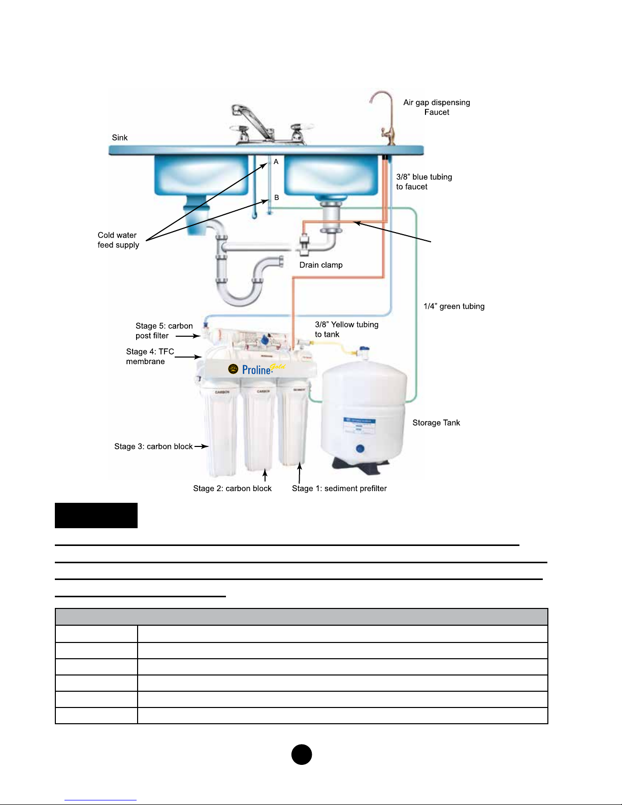
INSTALLATION DIAGRAM FOR PROLINE GOLD SYSTEM
3/8” red tubing
to drain clamp
(Fig. 1)
1/4” red tubing
from flow restrict
to air gap
WARNING:
CONNECT YOUR SYSTEM TO THE COLD WATER SUPPLY ONLY. DO
NOT USE WATER SUPPLY THAT IS MICRO-BIOLOGICALLY UNSAFE, OR
OF UNKNOWN SOURCE WITHOUT ADEQUATE DISINFECTION BEFORE
OR AFTER THE SYSTEM.
Tubing Directions
1/4” Green Feed water supply line to inlet. Feed ball valve labeled “TO FEED”
3/8” Blue Carbon post lter elbow labeled “TO FAUCET” to center threaded shank of faucet
3/8” Yellow Carbon post lter tee labeled “TO TANK” to ball valve on storage tank
1/4” Red Flow restrictor labeled “TO DRAIN” to air gap 1/4” drain/barb inlet at faucet air gap
3/8” Red 3/8” Barb on air gap to DC-38J Drain clamp
Color Coded Tubing
2
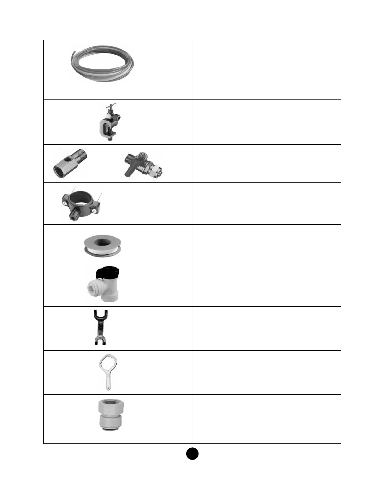
Installation Kit Contents
color tubing
SV-01
AD-4BC-3W BV-2BC
1. Color Coded Tubing:
Color Coded Tubing ( 5 coils, 4 colors)
¼’’ Green Tubing (approximately 8 feet)
¼’’ Red Tubing (approximately 6 feet)
3/8’’ Yellow Tubing (approximately 6 feet)
3/8’’ Blue Tubing (approximately 6 feet)
3/8” Red Tubing (approximately 5 feet)
Note: The color coded tubing matches
the color coded plugs on the PROLINE
2. SV-01:
SV-01 (Self Piercing Saddle Valve) for tapping
into cold water supply by piercing a hole in to copper
tubing. (See gure # 3)
3. BV-2BC (Chromed Ball Valve NPT ¼’’) and
AD- 4BC-3W (Chromed Adapter NPT ½’’) are used for
tapping into cold water supply at the top of undersink . If
you have a vinyl feed line or exible metal feed line use
the BV-2BC and AD- 4BC-3W. (see gure #2)
4. DC-38J
DC-38J (Drain Clamp) used for tapping into drainline for
discharge of the wastewater down the drain.
®
RO unit.
3/8” DC-38J (Drain Clamp)
Teon Tape
BV-103-EZ
Release Tool
WR-1W
5. Teon Tape:
Teon Tape is used on all threaded ttings to prevent
water leakage. Eight rotations (layers) are adequate
when using Teon tape to secure any threaded ttings.
The PROLINE® RO already has Teon tape on all of
its ttings.
6. BV-103- EZ:
BV-103-EZ (Storage Tank Ball Valve 3/8’’). In normal
operation, the Storage Tank Ball Valve must be in the
“open” position. Add 8 layers of Teon tape on top of
the Threaded tank outlet. Screw tank ball valve
securely on threaded 1/4” port.
7. Release Tool:
Release Tool (Quick Connect Release Wrench) allows
easier disconnecting of tubing ¼’’ and 3/8’’ from quick
connect ttings. Push release tool against collet of
quick connect tting and pull the tubing out of the
tting.
8. WR-1W :
WR-1W (White Wrench) Make sure the black rubber
O-ring is properly in place in the lter housing after
changing lters following any maintenance.
6FC6
9. 6FC6:
6FC6 (Faucet connector) to connect the faucet with
blue 3/8’’ tubing coming from the post lter labeled
TO FAUCET.
3
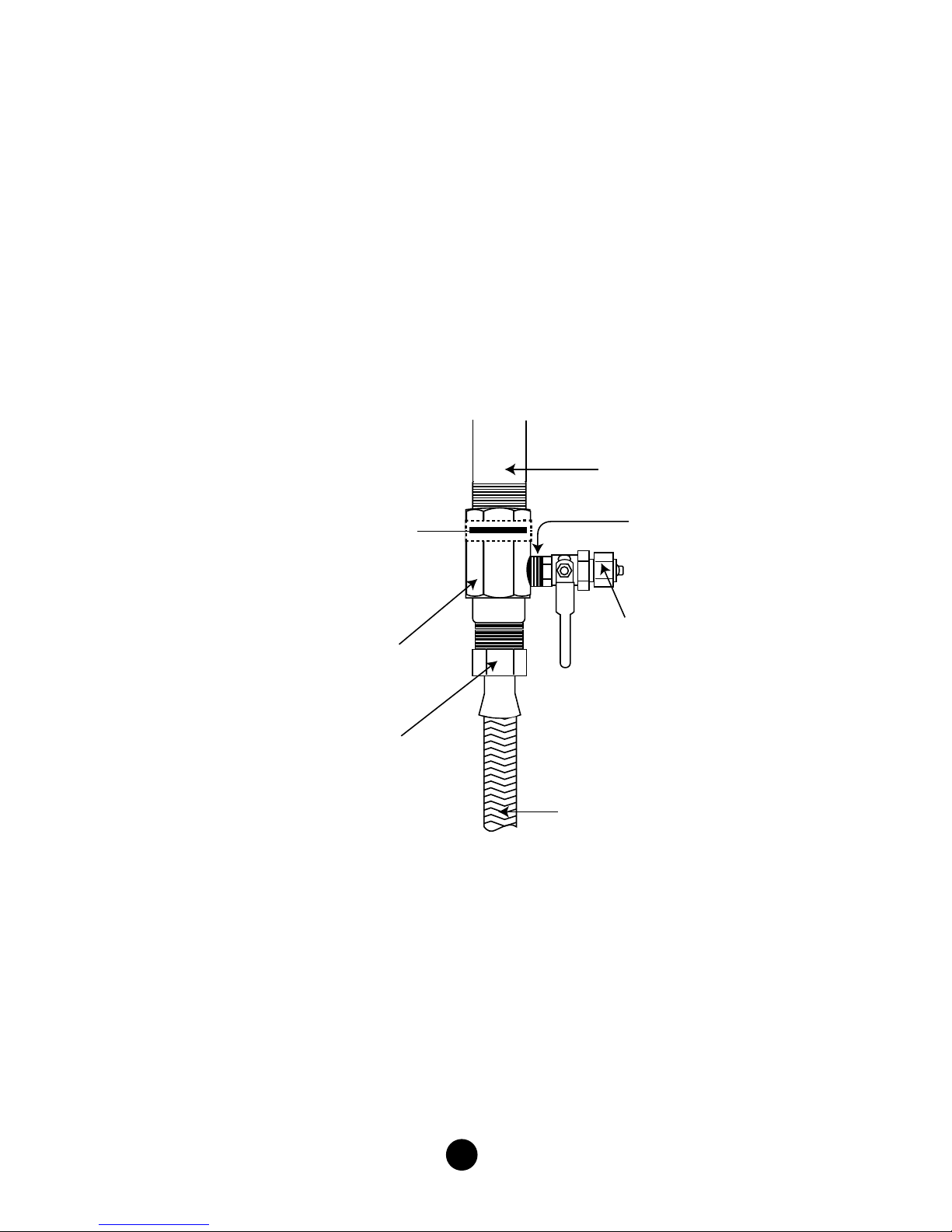
TAPPING INTO THE COLD WATER LINE
Flat washer
Water supply adapter
Ball valve
Apply teflon tape here
AD-4BC-3W
BV-2BC
(inside supply adaptor)
Base of the
cold water faucet
1/4” nut
1/2” threaded nut
with built in washer
Cold water supply
A - (Using the water supply adaptor Part # AD-4BC-3W & BV-2BC)
For ex metal or plastic line.
NOTE: The Proline® drinking water system must be connected to the COLD water
supply only.
1) Turn off the cold water supply to the sink faucet by locating the round or oblong
handle and turning clockwise until the water supply is off.
NOTE: If the cold water shut off valve fails to turn off the water, the house supply can
be turned off at the main water supply.
2) The water supply adapter (Fig. #2) may be installed at the faucet connection
(Fig. 2)
3) Disconnect the 1/2” threaded nut from the base of the faucet on the cold water
side. Place the at washer inside the female end of the water supply adapter.
Screw on the base of the cold water faucet.
4) Re-connect the 1/2” threaded nut onto the male threads of the adapter. “DO
NOT USE TEFLON TAPE ON THIS THREAD, RUBBER WASHERS WILL SEAL
THE CONNECTIONS”.
5) Place Teon tape on the 1/4” male threads of the ball valve supplied with the
adapter. Screw the ball valve into the 1/4” female port on the side of the adapter.
6) Remove the 1/4” nut from the ball valve, place the nut over the 1/4” Green tubing,
insert the tubing onto the barbed connection of the ball valve and tighten into
place with the 1/4” nut.
4
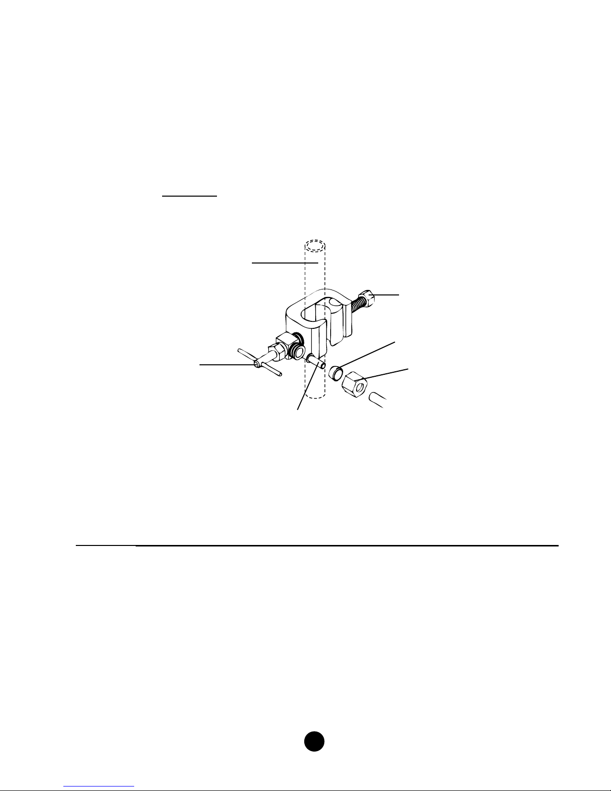
Brass nut
Cold water line
Brass insert
Plastic ferrule
Valve handle
Valve bolt
TAPPING INTO THE COLD WATER LINE
B - (Using self-piercing saddle valve Part # SV-01)
NOTE: This valve is designed for standard copper lines. If your cold water line is not
plumbed with copper line, use water supply adapter AD-4BC-3W & BV-2BC.
1) Turn off cold water supply under the sink and install the saddle valve to the cold line.
Clamp onto a smooth section and tighten valve bolt securely.
2) Turn the valve handle clockwise so that it pierces the copper cold water line.
3) Install the ¼’’ green tubing from the rst stage lter to the saddle valve (Fig. #3).
*Do not over tighten brass nut
(Fig. 3)
NOTE: All local plumbing codes must be followed to ensure proper installation and
use of your PROLINE® system.
NOTE: Use brass insert and plastic ferrule when connecting tubing to saddle valve.
Cold Water Supply Valve (Figure #3)
CAUTION: A pressure regulator is recommended for feedwater pressure above 80 psi.
5
 Loading...