

Page 1
保养
●烙铁头温度
温度过高会减弱焊铁头功能,因此应选择尽可能低之温度。此
烙铁头的温度回复力优良,较低的温度也可充分地焊接,可保护对
于温度敏感之元件。
●清理
应定期使用清洁海棉清理烙铁头,焊接后,烙铁头的残余焊剂
所衍生的氧化物和碳化物会损坏焊铁头,造成焊接误差,或者使烙
铁头导热功能减退。
长时间连续使用焊铁时,应每周一次拆开烙铁头清除氧化物,防止
烙铁头受损而减低温度。
●当不使用时
不使用焊铁时,不可让焊铁长时间处在高温状态,会使烙铁头
上的焊剂转化为氧化物,致使烙铁头导热功能大为减退。
●使用后
使用后,应抹净烙铁头,镀上新锡层,以防止烙铁头引起氧化
作用。
SS-227
Digital Temperature-Controlled
Soldering Station
Instruction Manual
说明手册
20
Please read the manual before using the unit.
Keep manual in accessible place for future reference.
感谢您购买此产品,使用前请详阅本使用说明书,阅
后请妥善保存,以备日后查阅。
©2010 Copy Right by Prokit’s Industries Co., Ltd.
2010001
Page 2
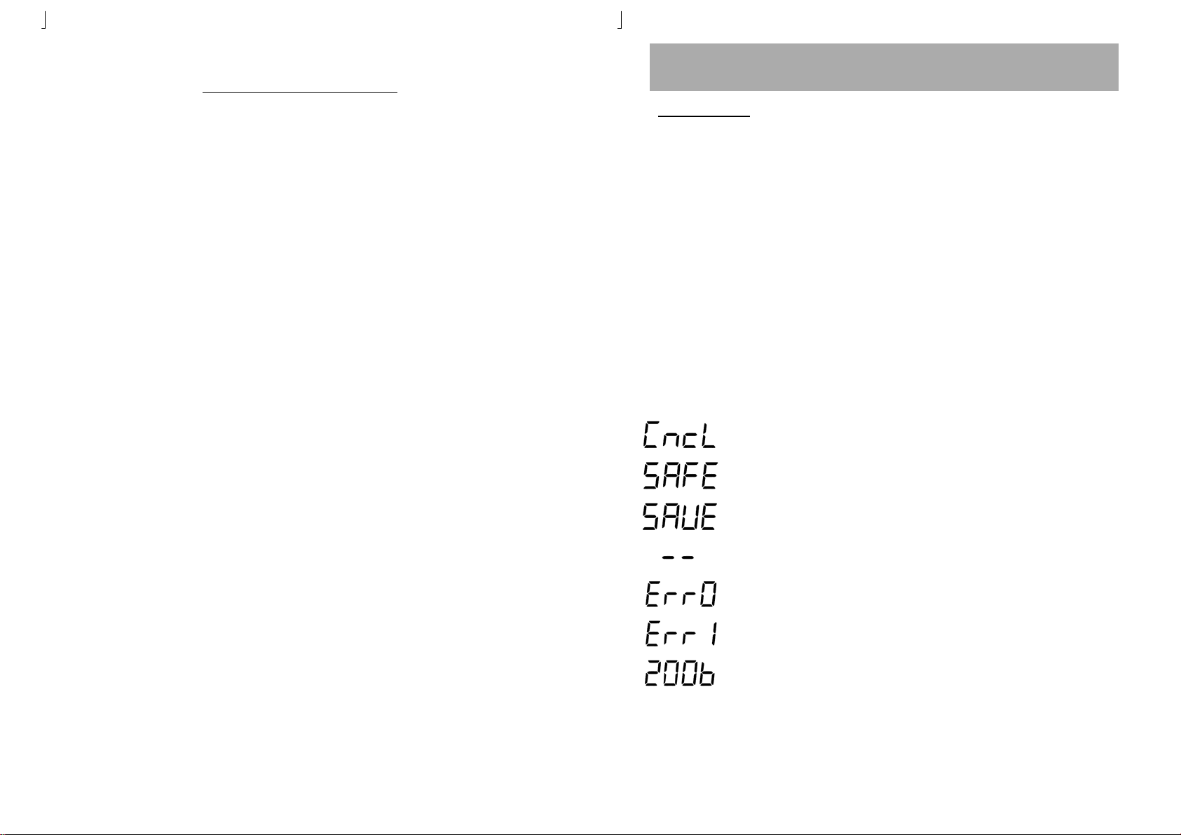
TABLE OF CONTENTS/ 目 录
Package Inclusion …………………………………… 3
Specifications …………………………………… 3
Safety Precautions …………………………………… 4
操作指南
Aoyue 936 规格
F. 计时器显示
1 .计时器显示打开或关闭的方法。
a.按住设定按键,过几秒后上排显示为“SET01”
b.反复按设置按钮,上排显示“SET05”。下排显示``
“OFF"。按加或减按钮可切换ON和OFF。
Functions and Features ……………………………… 5
Control Panel Guide ……………………………… 5
Operating Guidelines ……………………………. 6—10
Care and Maintenance …………………. ………….. 11
Basic Troubleshooting Guide ……………. ………….. 12
包装清单 ………….………………………………… 13
产品规格 ……………..……………………………... 13
安全事项 ………………………..………………… 14
功能与特点 ……..…………………………………… 15
控制指南 …………….…………………………… 15
操作指南 ……….………………….…………….. 16—19
保 养 …………………………………..………. 20
c.重复按设定按键,直到下排显示“SAUE"。按减按钮
可保存设定到内存里,并从设置模式中退出。
显示指南:
取消系统变化,从系统设定模式退出不保存任何更改。
系统锁定功能被激活。
储存系统的变化。保存系统设定和退出系统设定模式。
在睡眠状态。
错误显示0。标志着传感器或笔连接出现问题。
错误显示1。标志发热芯出现问题
字母“b”代表系统的睡眠已经开始进入倒计时状态,
2
19
Page 3
操作指南
Aoyue 936 规格
E. 温度显示方法
1.显示的温度可在摄氏和华氏模式之间切换。
2.按下面的方法可切换温度显示:
a.按住设定按键,过几秒后上排显示为“SET01”
b .反复按设置按钮,上排显示“SET03”。下排展示“° C”或“F"。按加
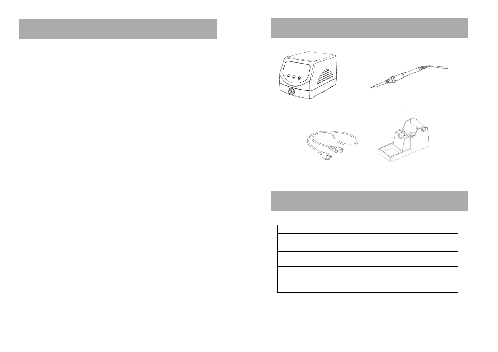
PACKAGE INCLUSION
或减按钮可切换摄氏和华氏模式。
c.重复按设定按键,直到下排显示“SAUE"。按减按钮可保存设定到内存
里,并从设置模式中退出。
F. 数字校准
校准头温度:
1.设置为所需的工作温度。
2.使用外部温度计检查烙铁头的温度。
3.等待显示器达到设定温度,然后等60秒让温度稳定下来。
4. 按住设定按键,过几秒后上排显示为“SET01”
5. 反复按设置按钮,上排显示“SET04”;下排会显示为“0000”,这表示
没有调过数字校准。
6.按加减按钮调整数字校准,负数表示降低烙铁头所对应设 置数值的温度
;正数表示增加烙铁头所对应设置数值的 温度。
7.调整直到外部温度传感器的数据等于我们的设定温度。
8.反复按设置按钮,直到显示屏显示单词“SAUE";按减 按钮可保存设
置内存里,并从设置模式中退出。
Soldering Iron
Soldering Station
Power Cord
Soldering Iron stand
SPECIFICATION
MAIN STATION
Voltage Input : available in 110V / 220V
Station Dimensions:
Weight: 1.5Kg
Power Consumption: 75W
Temperature Range: 200°C - 480°C
Heating Element Ceramic heater
Output voltage: 24V
120(w) x109 (h) x 165 (d) mm
9. 如果上述步骤还不能解决温度,就需要调节温度微调进行 校准。
18
Specification are subject to change without prior notice.
3
Page 4

SAFETY PRECAUTIONS
CAUTION: Improper usage can cause serious injury to personnel
and/or
SPECIFICATION
C. 睡眠功能
1.烙铁笔设有振动感应器。
操作指南
保养
● Check each component after opening the package to make sure
everything is in good condition. If there are any suspected damage, do not use the item and report the issue to your vendor.
● Turn OFF the main power switch and unplug the device from
power source when moving the device.
● Do not strike or subject the main unit (and all its components) to
physical shock. Use carefully to avoid damage to any part.
● Handle with care.
- Never drop or sharply jolt the unit.
- Contains delicate parts that may break if the unit is dropped.
● Make sure the equipment is always grounded. Always connect
power to a grounded receptacle.
● Temperature may reach as high as 480°C when switched ON.
- Do not use the device near flammable gases, paper and other flammable
materials.
- Do not touch heated parts, which can cause severe burns.
● Disconnect the plug from the power source if the unit will not be
used for a long period.
- Turn off power during breaks, if possible.
● Use only genuine replacement parts.
- Turn off power and let the unit cool down before replacing any part.
● The unit may produce a small amount of smoke and unusual odor
during initial usage. This is normal and should not yield any negative result when reworking.
● Soldering process produces smoke — use on well ventilated places.
● Do not alter the unit, specifically the internal circuitry, in any man-
ner.
4
2.当烙铁笔处于不使用状态,系统将自动进行倒计时。
3.通过以下方法可调睡眠计时功能。
a . 按住设定按键,过几秒后上排显示为“SET01”,这表明我们 可
以设定睡眠时间。
b. 按加或减按钮可调睡眠计时。如果显示“t000”,这等于睡眠功能
关闭。如果显示“t030”,睡眠功能是打开,并在30分钟后进入睡
眠状态。
c. 重复按设定按键,直到下排显示“SAUE"。此时按减按钮可保存
设定到内存并从设置模式退出。
4.如果睡眠功能倒计时已经开始,屏幕上会显示字母“b”。
5.当显示系统进入睡眠状态显示会有两个破折号“ - - "。如果 想唤醒
系统,拿起烙铁笔或按任何按钮,系统会立即开启, 恢复工作。
D.系统锁定
1.按下面的方法可设定系统锁定功能:
a.按住设定按键,过几秒后上排显示为“SET01”。
b.反复按设置按钮,上排显示“SET02”,下排显示“OFF"。按加或减
按钮可切换“ON”和“OFF”。
c.重复按设定按键,直到下排显示“SAUE";按减按钮可保存设定到内
存里,并从设置模式退出。
d.当系统锁定已启动,按任何按钮,屏幕会显示字“SAFE"指系统被
锁定了。
e.要解开系统锁定,同时按住三个按钮等过10秒后就会解锁。
17
Page 5

操作指南
Aoyue 936 规格
Aoyue 936 规格
注意: 进行连接和解开焊铁头时,切记要关掉电源,以免损
坏电路板。
A. 装置
1.将电源装置连接烙铁插座。
2.将烙铁头置放于烙铁架。
3.将插头插入电源插座,切记要接地。
4.烙铁座安装焊锡丝请看图A,B.
5.将海棉先湿水再挤干,置于烙铁架底座四个凹洞之上。海 棉要保
持潮湿状态。
B. 设定温度
烙铁座安装焊锡丝示意图A
烙铁手柄放置示意图B
FUNCTIONS and FEATURES
• Microprocessor-controlled ESD safe Soldering station.
• Ceramic heater with composite tip design.
• Compatible with Lead free applications.
• High power heating element for fast heat recovery.
• Integrated motion sensor in the hand piece.
• Selectable between Centigrade or Fahrenheit Scale
• Auto sleep and wake up function.
• System lock feature.
• Time display
• Digital offset
PANEL GUIDE
Timer
Set and Actual
Temperature Display
Increase / decease
button
Calibration Hole
Set Button
1.打开电源开关。
2.显示设定温度200至480℃,然后自动切换到显示实际温度。
3.若要增加或减少温度,按增加/减少按钮。
表示摄氏模式,显示为实际温度
表示摄氏模式,显示为设置温度,
表示华氏模式,显示为实际温度
表示显示的是设置温度, 摄氏模式
16
Main power
switch
Solder iron
connector
Fuse
AC power
receptacle
5
Page 6

Aoyue 936 规格
OPERATING GUIDELINES
REMINDERS:
1. Make sure the equipment is placed on a flat stable surface and
all the heat-generating components placed on their respective
holders or stands.
Ensure all switches are OFF before connecting to mains.
2.
3.
Ensure all terminal connections are properly secured
Aoyue 936 规格
功能与特点
• CPU控制,防静电设计。
• 陶瓷加热器。
• 可以用来焊接无铅锡。
• 大功率发热芯可快速加热和恒温。
• 手柄设有摇动感应器。
• 可选摄氏或华氏的显示方法
A. INITIAL PROCEDURES
1. Insert the power cord into the receptacle at the back of the station.
2. Plug the power cord into a grounded wall socket. The station is
protected against electrostatic discharge and must be grounded for
full efficiency.
3. Be sure the power switch is OFF before connecting or disconnecting
the soldering iron cord. Failure to do so may result in damage to
the circuit board.
4. Install solder wire to the solder iron holder.
5. Attach the soldering iron to the output at the bottom right area of
the station.
6. Place soldering iron to the soldering iron stand as shown in the figure below.
7. Dampen the sponge with water and squeeze dry before using. The
tips maybe damaged when used with dry sponge.
• 设有自动睡眠功能。
• 系统锁定功能。
• 计时显示
• 数字校准
计时显示
显示设置/实际温度
设置温度加/减
控制指南
微调
设定按键
烙铁连接插口
8. The unit is now ready for use.
6
电源开关
15
保险管
电源插座
Page 7

安全事项
警告:不当使用可能导致使用者受伤或对涉及物体造成
损坏。为保证操作安全,请严格遵守以下注意事项:
1.本机使用前保证接地良好。
2.开机前应将机器检查一遍:
A、部件是否有松动,脱落的现象。
B、所有外接线(电源线、连接线)是否正确连接。
OPERATING GUIDELINES
B. TEMPERATURE CONTROL
1. Turn the power ON.
2. The display would show a number between 200 to 480 indicating
the set temperature.
3. The display would then switch to showing the actual temperature.
4. To Increase or decrease the temperature, press the temperature
control increase/ decrease buttons.
Indicates that the number displayed is the Actual Temperature in Celsius scale
SPECIFICATION
保养
3.切勿触及烙铁头附近的金属部分。
4.切勿在易燃物体附近使用烙铁头。
5.通知工厂其他人士,烙铁头极为灼热,可能引发危险
事故。休息时或完工后应关掉电源。
6.更换部件或装置烙铁头时,应关掉电源,并待烙铁头
冷却至室温。
7.切勿使用烙铁台进行焊接以外的工作。
8.切勿将烙铁头敲向工作台来清除焊剂残余,此举动可
能严重震损烙铁头。
9.切勿擅自改动电焊台。
10.更换部件时,应采用原厂原件。
11.切勿弄湿电焊台,或手湿时也不能使用电焊台。
12.焊接时会冒烟,工作场所应有良好通风设施。
13.使用电焊台时,不可作任何伤害身体或损坏电焊台的
妄动。
14.移动设备时要断电。
14
Indicates that the number displayed is the Set Temperature in Celsius scale
Indicates that the number displayed is the Actual Temperature in Fahrenheit Scale
Indicates that the number displayed is the Set Temperature in Fahrenheit scale
C. SLEEP FUNCTION
1. The Soldering Iron is equipped with a vibration sensor.
2. When the soldering iron has been left unmoved the system would
begin countdown for the sleep timer.
3. Sleep timer is configurable via the following method.
◆ With the unit turned On, press and hold the SET button.
◆ Wait for the upper display to change to “Set 01”, this indicates that
we can now set the sleep timer. Press the increase or decrease
buttons to switch the sleep timer ON or OFF. If the display shows
“t000” this means that the sleep function is turned OFF. If the
display shows “t030” this means that the sleep function is turned On
and is set at 30 minutes.
◆ Save the new settings by repeatedly pressing the SET button until
the display shows “SAUE”. Press the decrease button to save the
new settings into memory.
◆ Saved settings are stored into memory and will remain in effect
unless changed by the user.
7
Page 8

OPERATING GUIDELINES
4. If sleep function is engaged the sleep timer will commence countdown
when the unit and hand piece has been left idle for a few seconds. To
indicate the countdown timer has started the display will show a letter
“b”.
5. Whet the countdown timer has expired the display would show two
dashes “ - - “ indicating the system is now in sleep mode.
6. To wake the system from sleep mode, pick the solder iron pen or push
any button.
7. The system would immediately wake up and resume working.
D. SYSTEM LOCK
1. The unit is provided with a system lockout feature to prevent accidental
altering of set temperatures and system configuration.
2. To enable the system lock feature follow the procedures below:
◆ While the unit is ON , press and hold the set button.Wait for the upper
display to change to “Set 01”.
◆ Repeatedly press the set button unit upper display shows “Set 02”. The
lower display would show “ OFF” . Press the increase or decrees button
to switch between On and OFF state
◆ To save the settings repeatedly press the SET button until the display
shows “SAVE”. Press the decrease button to save the settings and exit
from the settings adjusment mode.
◆ Saved settings are stored into memory and will remain in effect even af-
ter complete power off.
3. When system lock has been activated pressing any of the button will
have no effect. The display will show the letters “SAFE” indicating system
is in lock-out mode.
4. To dis-engage the system lock-out, press and hold all three buttons for
more than ten seconds.
8
Aoyue 936 规格
包装清单
烙铁手柄
主机
电源线
烙铁座
产品规格
主机
输入电源: 交流110V / 220V
尺寸:
重量:
功率:
温度显示范围:
加热方式: 陶瓷发热器
输出电压:
上述规格和设计可能变更,恕不另行奉告。.
120(w) x109 (h) x 165 (d) mm
1.5Kg
75W
200°C - 480°C
24V
13
Page 9

BASIC TROUBLESHOOTING GUIDE
PROBLEM 1: THE UNIT HAS NO POWER
1. Check if the unit is switched ON.
2. Check the fuse. Replace with the same type if fuse is blown.
3. Check the power cord and make sure there are no disconnections.
4. Verify that the unit is properly connected to the power source.
PROBLEM 2: TEMPERATURE IS NOT INCREASING
Description: Tip temperature does not increase, display shows the word “E rr0 ”
SOLUTION:
The solder Iron is not connected or its connection is loose ly connected to the main station. Plug the solder iron firmly and lock into position.
CASE 2: Solder Iron is properly connected, d isplay still shows “Err0”
SOLUTION:
The sensor or wires of the sensors may have been damaged. Replace heating element
(sensor is integrated into the heating element). Check the wirings of the solder iron pen.
CASE 3: Solder Iron is properly connected, disp lay shows “Err1”
SOLUTION:
The heating element may have been reached the end of it life. Replace heating element.
Check the wirings of the solder iron pen.
PROBLEM 3: SOLDER IRON IS OVERHEATING
Description: S older iron tip is getting too hot while the displayed actual temperature
stays below 200.
SOLUTION:
If the heating element have just been replaced then the heating element wires might
have been soldered incorrectly. Heating element have polarities and should be soldered
accordingly.
PROBLEM 4: OTHER PROBLEMS NOT MENTIONED IN THIS DOCUMENT
SOLUTION: Please bring the unit to a certified service station.
12
OPERATING GUIDELINES
Aoyue 936 规格
E. TEMPERATURE SCALE
1. The displayed temperature can be toggled between the centigrade
scale or the Fahrenheit scale.
2. To switch between the two scales follow these procedures:
◆ While the unit is ON , press and hold the set button. Wait for the
upper display to change to “Set 01”.
◆ Repeatedly press the set button unit upper display shows “Set 03”.
The lower display would show “ °C” or “°F”. Press the increase or
decrees button to switch between the two scales.
◆ To save the settings repeatedly press the SET button until the
display shows “SAUE”. Press the decrease button to save the
settings and exit from the settings adjusment mode.
◆ Saved settings are stored into memory and will remain in effect
unless changed by the user.
F. DIGITAL OFFSET
The unit is provided with a digital offset feature for tip calibration.
To calibrate the tip temperature:
1. Set to desired working temperature.
2. Use an external temperature sensor to check the tip temperature.
3. Wait for the display to reach the set temperature of 350C, then allow the tip to idle at the sensor for 60 seconds for proper temperature measurement.
4. Press and hold the set button.Wait for the upper display to change
to “Set 01”.
5. Repeatedly press the set button unit upper display shows “Set 04”.
The lower display would show “ 0000” . This indicates that indicates
that the digital offset is currently set at neutral.
6. Press the increase and decrease button to adjust the digital offset. A
negative number denotes a negative offset and a positive number
denotes a positive offset.
9
Page 10

OPERATING GUIDELINES
Aoyue 936 规格
7. Adjust the offset number until the external temperature sensor
reading is equal to our set temperature.
8. Repeatedly press the SET button until the display shows the word
“SAUE”. Press the increase button to save and exit from the system
configuration mode.
9. The tip has now been properly calibrated.
F. TIMER DISPLAY
The timer display can be turned on or off by the following method.
1. Set to desired working temperature.
2. While the unit is ON , press and hold the set button.Wait for the
upper display to change to “Set 01”.
3. Repeatedly press the set button unit upper display shows “Set 05”.
The lower display would show “ ON or OFF” . Press the increase or
decrees button to switch between On and OFF state
4. To save the settings repeatedly press the SET button until the
display shows “SAVE”. Press the decrease button to save the
settings and exit from the settings adjusment mode.
Display Guide:
Cancel system changes, exit from system configuration mode without saving any changes.
System Secure function is activated.
Save system changes. Save system configuration and exit from
system configuration mode.
In sleep mode.
Error message0. Signifies problem with sensor or pen connection.
Error message1. Signifies problem with heater.
10
The letter “b” indicates system has been idle and will enter sleep
mode after sleep timer expires.
CARE AND MAINTENANCE
1. Tip Temperature : High temperature shortens tip life and
may cause thermal shock to components. Always use the lowest
possible temperature when soldering.
2. Cleaning : Always clean the soldering tip before use to remove
any residual solder or flux adhering to it. Use a clean and moist
cleaning sponge. Contaminants on the tip have many detrimental
effects including reduced heat conductivity which contribute to
poor soldering performance.
3. After usage: Always clean the tip and coat it with fresh solder
after use. This guards against oxidation and pro-longs tip life.
4. System Care: Never allow the unit to stay idle at high temperature
for extended periods. Utilize the automated sleep feature to conserve energy, pro-long tip and heating element life. If unit will not
be used for long periods it is advised to power down the unit and
unplug from the mains.
5. Inspecting and cleaning the tip:
◆ Set the temperature to 250
◆ When the temperature stabilizes, clean the tip and check its condi-
tion. If the tip is badly worn or deformed, replace it.
◆ If the solder plated part of the tip is covered with black oxide, apply
fresh solder containing flux and clean the tip again. Repeat until all
the oxide is removed hen coat the tip with fresh solder.
◆ Never file the tip to remove oxide.
◆ Remaining oxides such as the yellow discoloration on the tip shaft
can be removed with isopropyl alcohol.
o
C.
11
 Loading...