

Page 1
SS-206/SS-207
Temperature-Controlled Soldering Station
User’s Manual
st
Edition, 2013
1
©2013 Copy Right by Prokit’s Industries Co., Ltd.
Page 2
Thank you for purchasing the SS-206/SS-207 Temperature-Controlled Soldering Station.
Please read this manual before operating the SS-206/SS-207 the manual in a safe, easily accessible
place for future reference.
Features
• Comply with CE, ESD safe certification.
• Temperature range 200 - 480ºC (392-896℉)
• Soldering iron handles are insulated and ergonomic-designed for ease and comfort.
• CPU Control, ceramic heater offer stable power and fast thermal recovery
• Celsius or Fahrenheit temperature unit selection
• Control IC modular design for easy and quickly repair.
• Stackable to conserve bench space
Packing List
Please check the contents of the Soldering station package and confirm that all the items listed below are
included.
Soldering Station………..…………1 Iron Stand(with cleaning sponge)….………………..1
Soldering Iron………………………1 User’s Manual……………….……………………………1
Power Cord…………………………1
Precautions
In this instruction manual, "caution" are defined as follows.
CAUTION:
Misuse may potentially cause injury to the user or physical damage to the objects involved.
For your own safety, be sure to comply with these precautions.
When the power is on, the tip temperature is between 200°C/392°F and 480°C/ 896°F. Since mishandling
may lead to burns or fire, be sure to comply with the following precautions.
Do not touch the metallic parts near the tip.
Do not use the product near flammable items.
Advise other people in the work area that the unit can reach a very high temperature and should be
considered potentially dangerous.
Turn the power off while taking breaks and when finished using the unit.
Before replacing parts or storing the unit, turn the power off and allow the unit to cool to room
temperature.
To prevent damage to the unit and ensure a safe working environment, be sure to comply with the
following precautions.
Do not use the unit for applications other than soldering.
Do not rap the soldering iron otherwise subject the iron to severe shocks.
Do not modify the unit.
Use only genuine replacement parts.
Do not wet the unit or use the unit when your hands are wet.
The soldering process will produce smoke, so make sure the area is well ventilated.
While using the unit, don't do anything which may cause bodily harm or physical damage.
1
Page 3
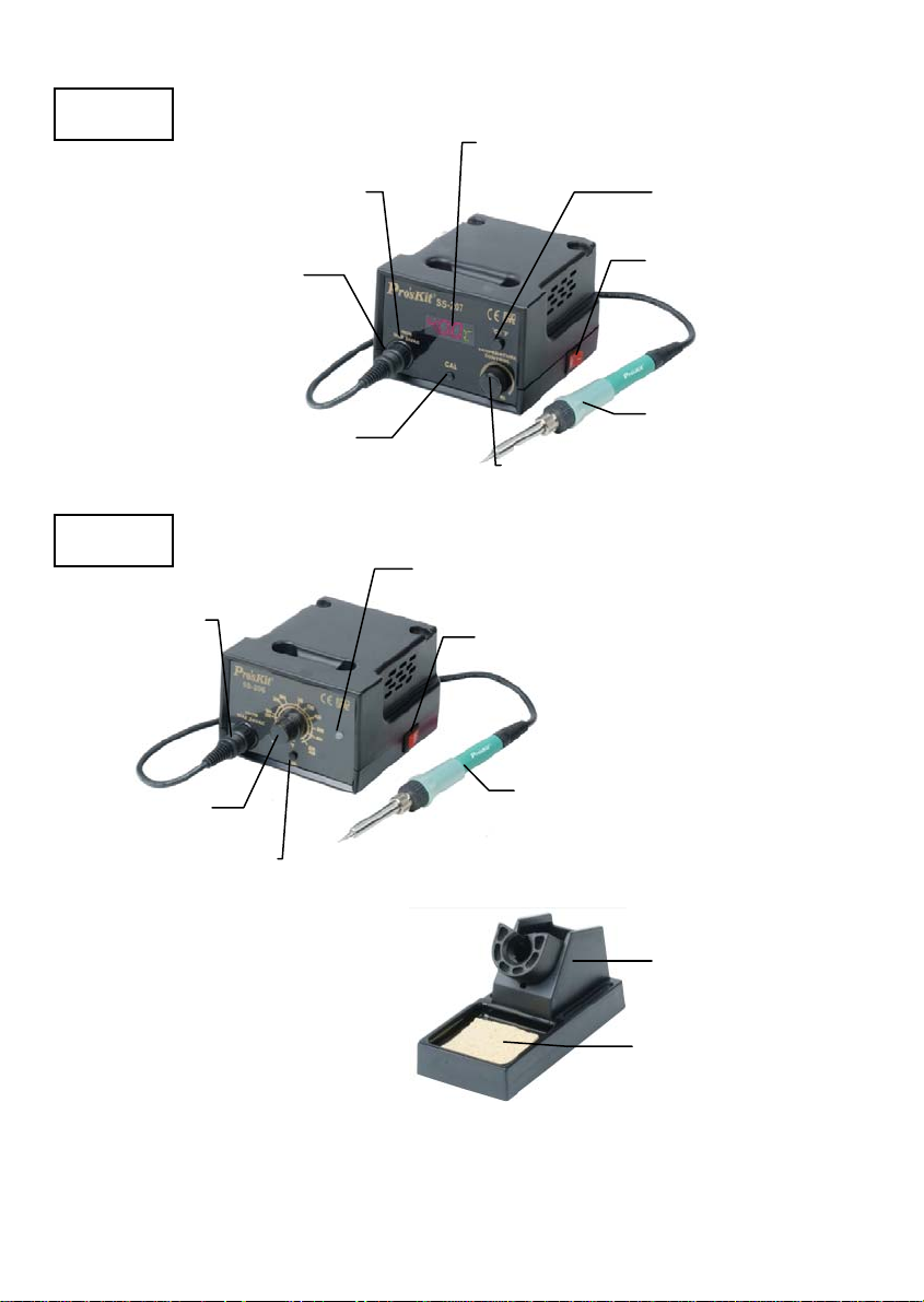
Names of Parts
p
p
SS-207
SS-206
Soldering iron
rece
Temperature
control knob
Soldering iron
rece
tacle
Calibrator
Heater Indicator
tacle
Calibrator
Temperature
y
displa
℃/ ℉ Switch
Power switch
Soldering iron
Heater Indicator
Temperature
control knob
Power switch
Soldering iron
Soldering
iron stand
Cleaning
spon
ge
2
Page 4
Specification
Model No. SS-206B SS-206E SS-206H SS-206E7
Display Analog
Voltage(V) AC 110V/220V Switch AC 127V/240V Switch
Power consumption 60W
Output voltage 24VAC
Heater Ceramic heater
Temperature range 200℃-480℃(392℉-896℉)
Station size (mm) 115x95x130
Standard Plug B type E type H type E type
Fuse 250V / 2A
Replacement heater 9SS-900-HT
Replacement handpiece 5SS-200-IRON
Individual packing Color Box
Model No. SS-207B SS-207E SS-207H SS-207E7
Display Digital
Voltage(V) AC 110V/220V Switch AC 127V/240V Switch
Power consumption 60W
Output voltage 24VAC
Heater Ceramic heater
Temperature range 200℃-480℃(392℉-896℉)
Station size (mm) 115x95x130
Standard Plug B type E type H type E type
Fuse 250V / 2A
Replacement heater 9SS-900-HT
Replacement handpiece 5SS-200-IRON
Individual packing Color Box
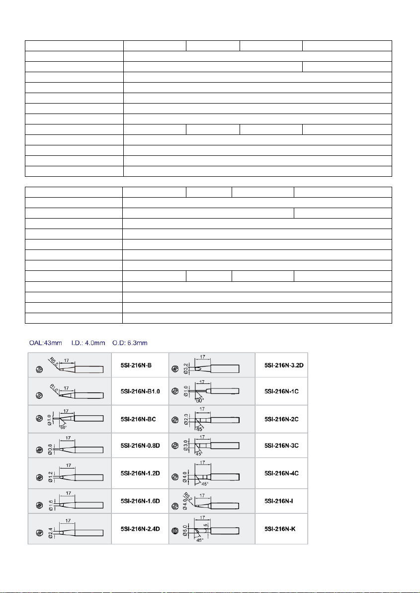
Replacement Tips:
Setting up & operating the Soldering Station
3
Page 5
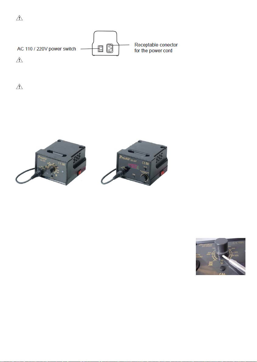
Warning:
Before use, please make sure the AC voltage, and turn the AC 110/220V switch to the correct position.
CAUTION: the sponge is compressed. It will swell when moistened with water.
A. Iron Holder
Before using the unit, dampen the sponge with the water and squeeze it dry.
CAUTION: Be sure to turn off the power switch before connecting or disconnecting the soldering iron.
Failure to do so may damage the P.W.B.
B. Connections
1. Connect the soldering iron cord into the receptacle.
2. Place the soldering iron on the iron holder.
3. Plug the power cord into the power supply. Be sure to ground the unit.
SS-206 SS-207
C. Set the Temperature
1. Turn the power switch on.
2. Set the temperature control knob to the desired temperature.
3. When the tip temperature reaches the setting temperature, the heater indicator of SS-207 will flash then
off, it means the temperature under control now. The heater indicator of SS-206 lights up green, means
ready to use, if it lights up red, means on heating now.
4. Lock the knob. (Only for SS-206 Model as shown)
.Set the control knob to desired temperature.
.Tighten the screw of inside control knob by Phillips screwdriver.
.Release screw anticlockwise before reset temperature.
For user convenience, and soldering efficiency, two stations can be stacked
securely.
CAUTION: The soldering iron must be placed on the iron holder when not in use.
Tip maintenance and use
Tip temperature
High soldering temperature can degrade the tip. Use the lowest possible soldering temperature.
The excellent thermal recovery characteristics ensure efficient and effective soldering even at low
temperatures. This also protects the soldered items from thermal damage.
4
Page 6

Cleaning
Clean the tip regularly with a cleaning sponge, as oxides and carbides from the solder and flux can form
impurities on the tip. These impurities can result in defective joints or reduce the tip's heat conductivity.
When using the soldering iron continuously, be sure to loosen the tip and remove all oxides at least once
a week. This helps prevent seizure and reduction of the tip temperature.
When not in use
Never leave the soldering iron sitting at high temperature for long periods of time, at the tip's solder plating
will become covered with oxide, which can greatly reduce the tip's heat conductivity.
After use
Wipe the tip clean and coat the tip with fresh solder. This helps prevent tip to oxidation.
Maintenance
Inspect and clean the tip
1. Set the temperature to 250°C (482°F)
2. When the temperature stabilizes, clean the tip with the cleaning sponge and check the condition of the
tip.
3. If there is black oxide on the solder-plated position of the tip, apply new solder (containing flux) and
wipe the tip on the cleaning sponge. Repeat until the oxide is completely removed, and coated with new
solder.
4. If the tip is deformed or heavily eroded, replace it with a new one.
CAUTION: Never file the tip to remove oxide.
Calibrating the iron temperature
The soldering iron should be recalibrated after changing the iron, or replacing the heating element or tip.
1. Connect the cord assembly plug to the receptacle on the station.
2. Set the temperature control the knob to 400°C (750°F).
3. Turn the power switch to 'ON' wait until the temperature stabilizes, Remove the CAL pot plug.
4. When the temperature stabilizes, use a straight-edge(-) screwdriver or small plus(+) screwdriver to
adjust the screw (marked CAL at the station) until the tip thermometer indicates a temperature of
400°C(750°F). Turn the screw clockwise to increase the temperature and counterclockwise to reduce
the temperature. Replace the CAL pot plug.
Tips
The tip temperature will vary according to the shape of the tip. The preferred method of adjustment uses a
tip thermometer. (See calibrating the iron temperature.)
5
Page 7

Troubleshooting Guide
Warning:
Disconnect the power plug before servicing. Failure to do so may result in electric shock. If the power cord
is damaged, it must be replaced by the manufacturer, its service agent or similarly qualified person in
order to avoid personal injury or damage to the unit.
Problem1.
The heater lamp does not light
up.
Problem 2.
The heater lamp lights up, but
the tip does not heat up.
Problem 3.
The tip heats up intermittently.
Problem 4.
Solder will not wet the tip.
Problem 5.
The tip temperature is too low.
Problem 6.
The tip can not be pulled off.
Problem 7.
The tip doesn't hold the desired
temperature.
Check 1. If the power cord and/or connecting plug disconnected?
*Connect it.
Check 2. If the fuse blew and eliminate the cause, replace the fuse.
A. Is the inside of the iron short-circuited?
B. Is the grounding spring touching the heating element?
C. Is the heating element lead twisted and short-circuited?
Check 3. Is the soldering iron cord broken?
*Refer to checking for breakage in the cord assembly.
Check 4. Is the Heating element broken?
*Refer to checking for breakage in the heating element.
Refer to Check 3
Check 5. Is the tip temperature too high?
*Set an appropriate temperature.
Check 6. Is the tip clean?
*Refer to Tip maintenance and Use.
Check 7. Is the tip coated with oxide?
*Refer to inspect and clean the tip.
Check 8. Is the iron calibrated correctly?
*Recalibrate.
Check 9. Is the tip seized?
Is the tip swollen because of deterioration?
*Replace the tip and the heating element.
Check 8
Checking for breakage of the heating element and cord assembly
Disconnect the plug and measure the resistance value between the connecting plug pins as follows.
If the values of 'a' and 'b' are outside the above value, replace the heating element (sensor) and/or cord
assembly .Refer to Procedures 1 and 2 If the value of C' is over the above value, remove the oxidization
film by lightly rubbing with sand-paper or steel wool the points as shown.
a. Between pins 1 & 5
(Heating Element)
11- 16Ω
b. Between pins 2 & 4 (Sensor) 0.5Ω-1. 5Ω
c. Between pin 3 & Tip Under 2Ω
6
Page 8

Heating Element Broken
Disassembling the Unit
1. Turn the nut 1 counterclockwise and remove the tip enclosure 2 , the tip 3 .
2. Turn the nipple 4 counterclockwise and remove it from the iron.
3. Pull both the heating element 6 and the cord assembly 11 out of the handle 12. (Toward the tip of the
iron.)
4. Pull the grounding spring 5 out of the D-sleeve.
Measure when the heating element is at room temperature.
1. Resistance value of heating element (resistance between the 2 red lines) 11-16Ω
2. Resistance value of sensor (resistance between white line and blue line) 0.5Ω-1. 5Ω
If the resistance value is not normal, replace the heating element.
Two ways of checking negative pole and positive pole of the sensor:
1. Touch the two sides of sensor with a magnet, the side that emits antimagnetic is the positive side.
The side does not have any magnetism is the negative side.
2. Heats up the heating element by hot water or fire, check the electric potential between 2 leads of sensor
by multimeter in mV measurement, if the meter display positive mV sign, the red test lead side should
be the positive side of sensor.
Replace the Heating Element.
(1) De-solder the damaged heating element leads and remove it.
(2) Replace a new one and solders to PC board properly.
7
Page 9

Solders the positive blue lead of sensor to the PC board which link to the blue lead of wire.
Solders the negative red lead of sensor to the PC board which link to the white lead of wire
(3) Solders the two lead of heater to the other side of PC board, bend the leads at right triangle when
soldering to prevent short-circuit
After heating ele
1. Measure the resistance value between pins 2 & 1 or pins 3 & 1 or pin 3 & 2. If it is not ∞, the heating
element or sensor touching the housing ground, it must be eliminated; otherwise will damage the PCB
2. Measure the resistance value between all leads' to confirm that the leads are not twisted and that the
grounding spring is properly connected.
Soldering iron cord damaged
Testing the soldering iron cord
Check the resistance between the pin of the plug and the wire on the terminal.
Pin 1: Red Pin 2: Blue Pin 3: yellow Pin 4: White Pin 5: Red
The value should be <2Ω. If it is more than 2Ω or ∞, the soldering iron need to be replaced.
Fuse replacement
When fuse is blown, replace with the same type of fuse. (refer to below picture)
1. Unplug the power cord from the power receptacle.
2. The fuse holder is located under the AC power receptacle, use the slotted (–) screwdriver to loosen
the fuse holder
3. Replace the fuse with new one
4. Put the fuse holder back in place
ment replaced:
Heating element lead diagram
8
Page 10

SS-206/SS-207 防靜電焊台
感謝您選購 SS-206/SS-207 防靜電焊台。使用焊台前請詳閱本使用說明書,閱後請妥為
收存,以備日後查閱。
特性
符合CE、ESD 安全規範.
溫度範圍200 - 480ºC (392-896℉)
烙鐵手柄隔熱效果佳,符合人體工學操作舒適
採用精密CPU數位控溫電路和陶瓷發熱體,功率穩定升溫速度快
攝氏與華氏溫度顯示功能
控制板模組化設計,容易維修
外型流線可堆疊外型,節省使用空間
包裝清單
請檢查產品包裝,以證實所列清單項目正確無誤:
電焊台……………………1 烙鐵座(包含清潔海綿)…………………..1
烙鐵………………………1 使用說明書…………………………………..1
電源線……………………1
注意事項
本使用說明書"注意"的定義如下:
注 意:濫用可能導致使用者受傷或對涉及物體造成實質破壞。為你本人安全著想, 請嚴格遵
守"注意事項"
當接通電源時,烙鐵頭溫度高達攝氏 200 至 480 ºC(華氏 392 至 896℉)濫用可能導致灼傷或火
災,請嚴格遵守以下事項︰
.切勿觸及烙鐵頭附近的金屬部份
.切勿在易燃物體附近使用電焊台
.烙鐵頭極為灼熱,可能引發危險事故,休息時或完工後應關掉電源。
.更換部件或裝配烙鐵頭時,應關閉電源,並待烙鐵頭冷卻至室溫
為避免損壞電焊台和作業環境,應遵守下列事項︰
.切勿使用於焊接以外的工作, 勿擅自改動電焊台
.更換部件時,應採用原廠配件
.切勿將烙鐵敲擊工作臺以清除焊劑殘餘,此舉可能嚴重震損發熱體
.切勿弄濕電焊台,手濕時也勿使用電焊台避免觸電
.焊接時溶錫會冒煙,現場應有良好通風設備
.使用電焊台時不作任何可能傷害身體或損壞物體的舉動
9
Page 11

部件名稱
烙鐵連接插口
溫度校準鈕
SS-206
溫度指示燈
烙鐵連接插口
SS-207
溫度顯示
℃/ ℉ 切換開
電源開關
烙鐵
溫度調節旋鈕
溫度指示燈
電源開關
溫度調節旋鈕
溫度校準鈕
烙鐵架
海綿
10
烙鐵
Page 12

規格
型號 SS-206B SS-206E SS-206H SS-206E7
顯示 刻度型
電壓 AC 110V/220V 可切換 AC 127/240V 可切換
消耗功率 60W
輸出電壓 24VAC
發熱體 陶瓷發熱體
溫度範圍 200℃-480℃(392℉-896℉)
焊台尺寸(mm) 115x95x130
插頭 B型插頭 E 型插頭 H 型插頭 E 型插頭
保險絲 250V / 2A
選購發熱體 9SS-900-HT
選購烙鐵 5SS-200-IRON
包裝 彩盒
型號 SS-207B SS-207E SS-207H SS-207E7
顯示 數顯型
電壓 AC 110V/220V 可切換 AC 127/240V 可切換
消耗功率 60W
輸出電壓 24VAC
發熱體 陶瓷發熱體
溫度範圍 200℃-480℃(392℉-896℉)
焊台尺寸(mm) 115x95x130
插頭 B型插頭 E 型插頭 H 型插頭 E 型插頭
保險絲 250V / 2A
選購發熱體 9SS-900-HT
選購烙鐵 5SS-200-IRON
包裝 彩盒
11
Page 13

選購烙鐵頭
裝置和使用焊台
注 意:使用前,請先確認 AC 電壓,並將 AC 110/220V 開關,撥到正確位置
AC110/220 開關
110
220
電源插入孔
A.
烙鐵架
注 意:海綿是可以擠壓物體,水濕則漲大,使用海綿時,先濕水再擠乾,否則會損壞烙鐵頭。
B.連接
注 意:進行連接和解開烙鐵時,切記要關掉電源,以免損壞電路板。
1.將烙鐵電源裝置連接電焊台之插座。
2.將烙鐵置放於烙鐵架。
3.將插頭插入電源插座,切記要接地
12
Page 14

SS-206 SS-207
C.設定溫度
1. 啟動開關
2. 將控溫旋鈕定在所需溫度點
3. 當達到設定溫度時,SS-207 溫度指示燈閃爍熄滅進入控溫狀態,SS-206 溫度指示燈綠燈亮起,
焊台進入可使用狀態,當紅燈亮起時為升溫狀況。
4. 溫度鎖定(SS-206 型焊台有此功能)(如圖)
溫度設定到適當溫度
使用起子在溫度旋鈕下順時針擰緊鎖定螺釘直至溫度設定旋鈕不動
溫度重新設定時,逆時針旋轉起子鬆動鎖定螺釘。
注意:烙鐵不使用時,請放置於烙鐵架.
烙鐵頭的維護和使用
烙鐵頭溫度
溫度過高會降低烙鐵頭壽命,因此應選擇適合工作溫度,烙鐵頭的溫度回溫速度快,較低的溫
度也可充分的焊接,可保護對於溫度敏感之元件。
清理
定期使用清潔海綿清理烙鐵頭,焊接後烙鐵頭的殘餘焊劑所衍生的氧化物和碳化物會損壞烙鐵
頭,造成焊接誤差,或使烙鐵頭導熱功能減退。長時間連續使用烙鐵時,應每周一次拆開烙鐵
頭清除氧化物,防止烙鐵頭受損而減低溫度並降低導熱速度。
當不使用時
不使用烙鐵時,不可讓烙鐵長時間處在高溫狀態,會使烙鐵頭上的焊劑轉化為氧化物,致使烙
鐵頭導熱功能大為減退。
13
Page 15

使用後
使用後應抹淨烙鐵頭,鍍上新錫層,以防止烙鐵頭引起氧化作用
保養
檢查和清理烙鐵頭
注 意:切勿用銼刀剔除烙鐵頭上的氧化物。
1. 設定溫度為攝氏250度(華氏482度)
2. 溫度穩定後,以清潔海綿清理烙鐵頭,並檢查烙鐵頭狀況。
3. 如果烙鐵頭的鍍錫部份含有黑色氧化物時,可鍍上新錫層,再用清潔海綿抹淨烙鐵頭,如此
重複清理,直到徹底除去氧化物為止,然後再鍍上新錫層。
4. 如果烙鐵頭變形或生銹,必須替換新的烙鐵頭
校準烙鐵溫度
每次更換烙鐵或替換發熱體、烙鐵頭後,應重新校准烙鐵溫度。
1. 將烙鐵電線的插頭插入焊台插座。
2. 利用控溫旋鈕設定所需溫度並鎖定該溫度點。
3. 當使用溫度與所定溫度有小量誤差時,請以"一"字螺絲起子旋轉焊台上帶有CAL字樣的校准
計,順時針方向扭轉是升溫,反時針方向是降溫。
烙鐵頭
不同款型烙鐵頭的溫度可能有所不同,調節的最理想方法是使用測量烙鐵頭之專用溫度計。
(參照"校准烙鐵頭溫度")
14
Page 16

排除故障說明
警 告: 進行維修之前應關掉電源,否則可能發生觸電事故。
若電線損壞,應請廠家或其維修服務代理商或專業合格人士修理,以免發生傷害身體或損壞焊
台。
故障1:發熱器指示燈不亮 檢查1. 電線或連接插頭是否鬆動?
.重新接妥。
檢查2. 保險絲是否燒斷?
.確定保險絲燒斷原因後進行修理,並更換同規格新保險絲。
a.烙鐵內部是否短路?
b.接地彈簧是否觸及發熱元件?
c.發熱元件引線是否扭曲和短路?
d.發熱器指示器是否燒壞?
故障2:發熱器指示燈雖亮,但
烙鐵頭不升溫。
故障3:烙鐵頭斷斷續續升溫時 →參考 檢查3.
故障4:烙鐵頭不上焊錫。 檢查5. 烙鐵頭溫度是否過高?
故障5:烙鐵頭溫度太低。 檢查7. 烙鐵頭是否衍生氧化物?
故障6:烙鐵頭無法取下。 檢查9. 烙鐵頭是否被緊夾?烙鐵頭是否因銹污而膨脤?
檢查3. 烙鐵電線是否破損?
.請參閱"組裝電線破損檢查法"。
檢查4. 發熱元件是否破損?
.請參閱"發熱元件破損檢查法"。
.重新設定適當溫度。
檢查6. 烙鐵頭是否已清理乾淨?
.請參閱"烙鐵頭維護和使用"。
.請參閱"檢查和清理烙鐵頭"。
檢查8. 烙鐵是否正確校准?
.重新校准。
.更換新的烙鐵頭及發熱元件。
故障7:烙鐵頭未升達所需溫度 →檢查8.
15
Page 17

如何檢查發熱元件和組裝電線破損
如果插頭引腳之間的電阻值與右表電阻值有差異,則需將烙鐵拆開後, 確認印刷電路板電阻值是
否正常, 檢測方式請參考替換發熱元件。
如印刷電路板(PCB)上測量電阻值正常,而插頭引腳之間的電阻值有差異,表示烙鐵電線破損,
請參考烙鐵電線破損之測試方法。
如果插頭第3腳與烙鐵頭之間電阻值大於上表電阻值,則要用砂紙或鋼絨輕輕擦除右圖所示部位
的氧化層。
拔出插頭,測試連接插頭的腳與腳之間的電阻值如下:
如何拆裝烙鐵︰
第1腳與第5腳
第2腳與第4腳之間(傳感器) 0.5Ω-1. 5Ω
第3腳與烙鐵頭之間 2Ω以下
之間 (發熱元件) 11Ω-16Ω
1.向反時針方向扭開螺帽 1 ,取出烙鐵頭護套 2 和烙鐵頭 3 。
2.向反時針方向扭開套頭 4 ,從烙鐵中拉出套頭。
3.從手柄 12 中取出發熱元件 6 和電線11 (向著烙鐵頭方向拉出)
16
Page 18

測量方法︰
注意:當烙鐵回復到室溫時測量
1. 發熱元件電阻值(兩條紅線之間的阻值): 11Ω-16Ω
2. 傳感器電阻值(白線及藍線間的阻值): 0.5Ω-1.5Ω
如果電阻值反常,更換發熱元件。
3. 檢測傳感器正負極的方法:
(1) 傳感器材料為正極-鎳鉻,負極-鎳矽,所以負極有較強的導磁性,用磁鐵吸試,可吸附的是
負極,正極不吸。
(2) 將發熱元件熱端放入熱水或火中產生熱源,再以萬用表的 mV 檔量測傳感器的兩端電位,如
果顯示正的 mV,紅表筆端量測的是正極
替換發熱元件
1. 將不良的發熱元件進行解焊拆除。
2. 替換新的發熱元件,點焊於PCB上。
發熱元件的傳感器正極藍線焊接到PC板上連接到電線藍色引線
發熱元件的傳感器負極紅線焊接PC板上連接到電線白色引線
注意︰發熱元件的傳感器有正負之分,接線錯誤可能導致其他元件的損壞。
17
Page 19

3. 發熱元件發熱芯引線用耐熱尼龍管護套保護,引線無正負極性區分,焊接時扭彎引線或正
三角形,以防止短路。
更換發熱元件後,請進行以下事項︰
1
. 測量烙鐵插頭第3腳和第1腳
則可能是發熱元件或傳感器,接地外殼之間有接觸,必須排除。 否則這將會損壞印刷電路
板。
2. 測量各線間電阻值是否符合, 確定引線未被扭曲,而接地彈簧也連接妥當。
烙鐵電線破損
測試烙鐵電線破損方法:
之間,第3腳和第2腳之間,第1和第2腳之間電阻值。如果不是∞,
插頭
發熱元件
在
引線示意圖
測試烙鐵插頭腳和終端板電線之間的電阻值。
腳1-紅色
烙鐵。
注意︰
實際接線方式以線路圖為準,變更引線外皮顏色時,恕不另告知。
更換保險絲:
當有誤用的狀況而造成保險絲燒斷時,可以自行更換新的保險絲,以一字起子拆下電源座下方
保險絲座後,裝上新的保險絲再裝回保險絲座即可。
腳2-藍色 腳3黃色 腳4-白色 腳5-紅色,電阻值應<2歐姆,若大過2歐姆或∞,應更換
18
Page 20

©2013 Prokit’s Industries Co., LTD. All rights reserved 2013001(C)
19
 Loading...