

Page 1
MT-310
5 Smart Clamp Meter
User’s Manual
1st Edition, 2013
©2013 Copy Right by Prokit’s Industries Co., Ltd.
Page 2

1-1 General Specifications
• All push button clamp multimeter without rotary switch, more safe and
convenient for operation.
• LCD display digits: 3999 digit large scale LCD readout
• Measuring rate: 5 times / sec.
• Over range display : OL as over range indication
• Auto power off with audible alert and disable function
• Full Icon display with backlight
• Automatic power off time: Approximately 15 minutes after power on.
• Conductor Jaws open up to 42mm
• Low battery indicator:
appears in the display
• Power requirement: 3V battery.
1-2 Environmental Conditions
• Indoor Use
• Calibration: One year calibration cycle.
• Operating temperature:
0°C ~ 30°C ( 80% RH)≦
30°C ~ 40°C ( 75% RH)≦
40°C ~ 50°C ( 45%RH)≦
• Storage temperature:
-20 to +60°C, 0 to 80% RH (batteries not fitted).
• Operating altitude: 2000m (6562 ft)
• Overvoltage category: IEC 61010-1 600V CAT. ,Ⅲ
CAT. equipment is designed toⅢ protect against the transients in the equipment
in fixed installations, such as distribution panels, feeders and short branch
circuits and lighting systems in large buildings.
• Conductor Size: 42mm diameter.
• Pollution degree: 2
• EMC: EN 61326-1
• Shock vibration: Sinusoidal vibration per MIL-T-28800E (5 ~ 55 Hz, 3g
maximum).
is displayed. Replace the battery when the indicator
1
Page 3
1-3 Electrical Specifications
Accuracy is ±(% reading + number of digits) at 23°C ± 5°C < 80%RH.
Temperature coefficient: 0.2 x (Specified accuracy) / °C < 18°C, > 28°C .
Voltage
Function Range Accuracy
4V ~ 400.0V ±(0.8%+ 4dgt)
ACV
600.0V ±(1.2%+ 4dgt)
4V ~ 400.0V ±(0.7% + 4dgt) DCV
600.0V ±(0.8+% + 5dgt)
Overload protection: 600 Vrms
Max Operation time: DT=30s for 30V ≧
Input impedance: 4K for input≧ voltage up to 30V. Impedance increase with input voltage
to approximate 200KΩ at 600V.
When measurement value less than 2V AC voltage or 200mV DC voltage, LCD monitor
will display “AUTO” symbol
and non values.
Resistance
Function Range Accuracy
400Ω ±(0.8% + 6 dgt)
Ω
4kΩ~4MΩ ±(0.8% + 2 dgt)
40MΩ ±(2.0% + 5dgt)
Overload protection: 600V rms
Max. open circuit voltage: 1.5V
Temperature coefficient multiply by 1.5 when operating temperature is temperature is 40°C
~ 50°C .
ACA
Function Range Accuracy
ACA
(50-60Hz)
40.0~400.0A ±(1.8%+5 dgt)
2
Page 4

Electric Field EF-Detection, Non-Contact Voltage
With Auto displayed on the LCD, press NCV button to enter the NCV function. The meter
displays EF. Signal strength is indicated as a series of bar graph segments on the display
and variable beep tones. See the specifications later in this manual for a complete
description of the bar graph indicators.
An antenna is located at the top right corner of the Conductor, which detects electric field
surrounding current-carrying conductors. It is ideal for tracing live wiring connections,
locating wiring breakage and to distinguish between live or earth connections.
* Probe-Contact EF-Detection
For more precise indication of live wires, such as distinguishing between live and ground
sockets, use the V ac manual function selection for direct contact voltage measurements.
EF Detection
Indication: Bar graph segments & audible beep tones proportional to field strength
Detection Frequency: 50/60 Hz
Detection Antenna: Top right corner of the Conductor
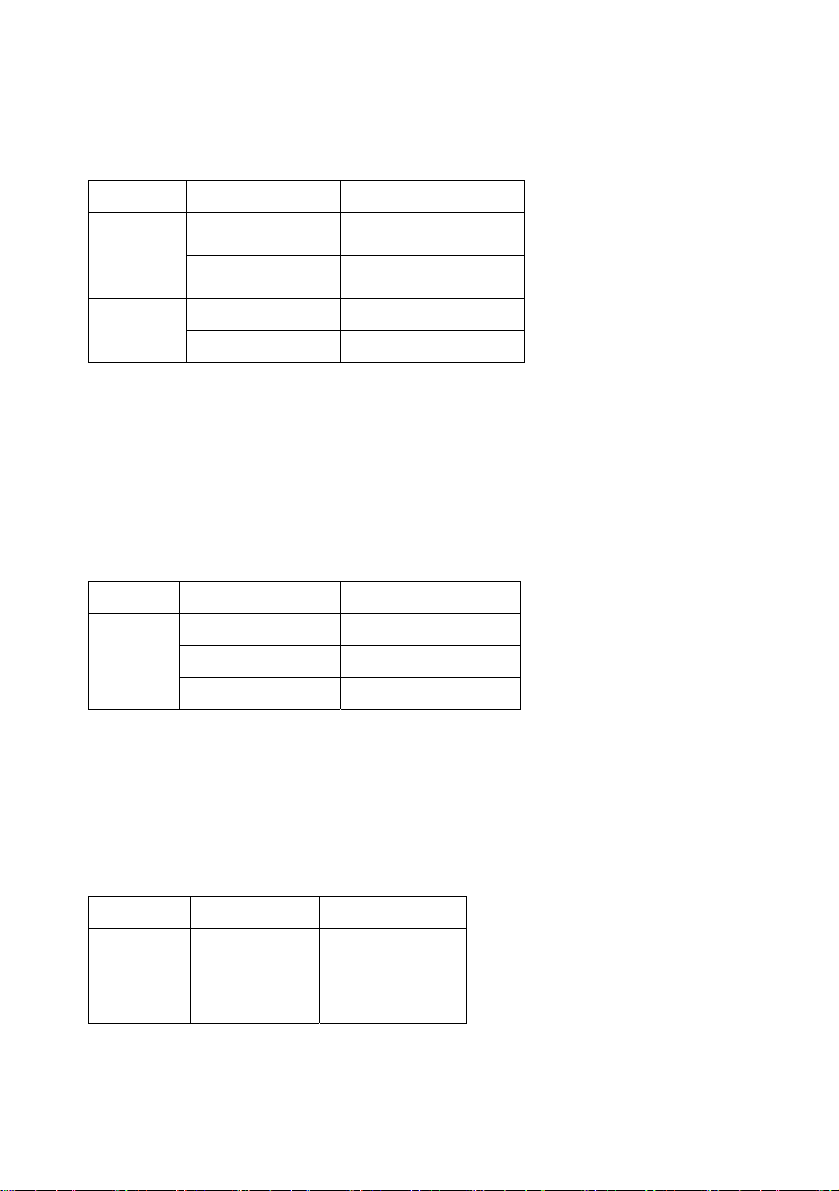
Typical Voltage Bar Graph Indication
15V-55V -
30V-85V - -
55V-145V - - -
ABOVE120V - - - -
Using Save and Read Features
1. Under any measurement mode, press SAVE button to enter save mode with beep
tone to indicate saving record is in process (number of records saved).
2. During measurement or AUTO mode, press READ button to exit the current
measurement mode or AUTO mode and to display the last number of saved reading.
Each presses to view the next saved reading, it is in first save last out bases. During
READ mode, press RESET button to exit.
3. The maximum number of reading saved is 10.
3
Page 5

MT-3105 智能型鉗錶
使用說明書
為了確保人身安全和防止損壞儀錶,使用者在使用之前必須仔細閱讀本手冊中的安全注意事
項。
1:接通儀錶電源時顯示 符號說明電池工作電壓低應及時更換電池。
2:檢查表筆,絕緣應完好無損。無斷線、脫頭和銅線裸露現象。
3:檢查儀錶殼體,應無破裂損壞現象。
4:表筆接入被測電路時應先接黑表筆,表筆與被測電路分離時應先斷開紅表筆。
5:為避免損壞儀錶,不要輸入超每個檔位所規定的最大值。
6:在測量高電壓時,應謹慎小心避免觸電,特別是不要接觸被測電路並保持一定距離,以
確保人身安全。
7:當使用儀錶進行測量時,絕對不要打開後蓋,以免有觸電危險。
8:在打開後蓋或更換電池前,應將表筆離開被測電路,並關斷電源。
9:在進行電流測量時,應儘量使被測線路位於儀錶鉤部的中心位置。
10:當你的儀錶或手是濕著的時候請勿使用儀錶進行測量。
11:為避免電擊。切勿使用已經損壞或不能進行正常操作的儀錶。
12:雖然有自動關機功能,但測量完畢後,還是要即刻關斷電源。
13:不要改動儀錶內部電路,以免損壞儀錶及安全。
14:應避免在直射陽光、高溫、高濕、易燃易爆及蒸汽和粉塵大的環境中使用或存放。
一、特點
此鉤表是採用最新設計、全功能按鍵操作、擁有最新外觀、採用雙色射出的新型數字鉤表。
儀錶使用大螢幕 LCD 4000 位元顯示。可用來測量交直流電壓,交流、電流,通斷等。具有
自動選擇,自動檔位,自動關機,資料保持,資料存儲和讀出,非接觸電壓檢測等功能。由
於使用二次射出的外殼設計,使用更安全、可靠。該系列儀錶具有結構精巧,操作容易,攜
帶方便等優點,是電氣測量的理想工具。此產品具有以下特點:
安全設計符合 IEC1010 國際標準。全系列產品通過 CE 國際安全認證。
殼體採用 ABS 阻燃材料,雙色二次射出成型,安全更有保證。
全按鍵功能組合,智慧應用,功能更完善。
自動選擇,自動檔位元,資料保持,資料存儲和讀出,非接觸電壓檢測。
10 分鐘自動關機功能,節省電池消耗。
大開口雙開鉤部設計,最大開口直徑(被測導體直徑)42 毫米。
安全、獨立電池盒設計,防止電池漏液腐蝕線路板,更換電池更方便。
全功能、檔位元超載保護,保護電壓 250 伏有效值。
高內阻保證最小的測量誤差(10 MΩ)液晶顯示字高 18mm。
二、一般特性
2.1:安全規範:IEC1010- Ⅱ級
2.2:最大顯示:4000
2.3:採樣速率:每秒 3 次
2.4:過檔位元顯示:顯示 OL,並有蜂鳴器聲音提示
4
Page 6

2.5:自動負極性“ "指示
2.6:低電壓指示:顯示符號
2.7:資料保持,顯示符號"HOLD"
2.8:自動關機:開機 10 分鐘後自動切斷電源,重複按鈕操作可開機
2.9:工作環境:0-40℃,相對濕度<75%
2.10:儲存環境:溫度-10-50℃,相對濕度<75%
2.11:電源:1.5V 電池 2 節。型式:SIZE AA,功耗:約 2mW
2.12: 外形尺寸:114.8mm X 56.9mm X 11.6mm
2.13:重量:約 175g(包括電池和表筆)
2.14:附件:帆布包,測試棒,電池,彩盒包裝。
三、使用方法:
3-1 按鍵功能:
• SAVE 鍵:測量資料存儲鍵,在任何測量模式下,按此鍵存進入測量資料存儲模式,可
存儲 10 組資料。
• READ 鍵:測量資料存儲讀取鍵,在自動測量模式下,按此鍵退出正在測量的模式顯示
最後存儲的資料,每按一次此鍵,按次序讀取最近測量的資料。在 READ 模式下,按
RESET 鍵退出此模式。
• HOLD 鍵:資料保持鍵,測量資料時,按壓該鍵,則鎖定當前測量資料,再次按壓可解
鎖定。(某些機型該按鍵為複合按鍵,短按為資料保持功能,長按為背光功能,重複按
壓操作可迴圈該功能)
• RESET 鍵:復位鍵,在儀錶正常使用過程中,該按鍵不會被用到,但當因意外操作引起
儀錶當機或退出 READ 模式時,則可使用該按鍵使儀錶重新進入工作模式。
• NCV 鍵:非接觸電壓偵測鍵,有此功能的儀錶,在按壓該按鍵後,儀錶人非接觸電壓偵
測功能,可用來進行非接觸電壓檢測。
• BK_LIGHT 鍵:背光鍵,該按鍵為專用背光按鍵,按壓一次,背光點亮,背光點亮後延
時 10 秒自動關閉,期間再次按壓該按鍵,背光關閉。
3-2 性能描述
準確度運算式:±(%讀數+字數),保證期為 1 年
環境條件:溫度 23±5℃相對濕度<75%
3-2-1 交流電流(ACA)
檔位 解析度 準確度
40A 0.01A
400A 0.1A
頻率回應:40-400Hz,最大輸入電壓 600V DC 或 AC(有效值)。
此鉤表會根據被測信號自動選擇進入對應的測試狀態。
注意:交流電流測量的最大額定電流為 400A,請不要嘗試去測量超過 400A 以上的
大電流,以免損壞儀錶。
注意:為避免電擊,測試前應取出儀錶的測棒。按下扳機,張開鉤部,卡入一根單
獨的導體。
注意:1.如果卡入兩個或兩個以上的導體,測量將無效。
為保證測量精度,被測導體需儘量位於鉤部中心位置,如圖所示。
±(1.8%rd+5dgt)
5
Page 7

讀取液晶顯示器上的被測電流值。
按下“HOLD“按鈕,將保持當前所得資料。如果在暗處無法讀數,可按下“LIGHT"鍵,
背光照明點亮。
3-2-2 交流電壓(ACV)
量程 解析度 準確度
4V 1mV
40V 10mV
400V 100mV
600V 1V ±(1.2%rd+4dgt)
輸入阻抗 10MΩ,最大輸入電壓 600V DC 或 AC(有效值)。
此鉤表會根據被測信號自動選擇進入對應的測試狀態。
注意:交流電壓測量的最大額定電壓為 600V,請不要嘗試去測量超過 600V 以上的電壓,
以免損壞儀錶。
將黑表筆插入“COM"插孔,紅表筆插入“V、Ω"插孔。將紅、黑表筆接入被測電路。讀
取液晶顯示器上的被測電壓值。資料保持按“HOLD"健,背光按"LIGHT"健。
當 ACV 量測值低於 2V 時,LCD 螢幕會顯示"AUTO"符號,無數值顯示。
3-2-3 直流電壓(DCV)
量程 解析度 準確度
4V 1mV
40V 10mV
400V 100mV
600V 1V ±(0.8%rd+5dgt)
輸入阻抗 10MΩ,最大輸入電壓 600V DC 或 AC(有效值)。
此鉤表會根據被測信號自動選擇進入對應的測試狀態。
注意:直流電壓測量的最大額定電壓為 600V,請不要嘗試去測量超過 600V 以上的電
壓,以免損壞儀錶。
將黑表筆插入“COM"插孔,紅表筆插入“V、Ω"插孔。將紅表筆接入被測電路的正極、
黑表筆接入被測電路的負極。讀取液晶顯示器上的被測電壓值。資料保持按“HOLD"健。
背光按"LIGHT"健。
當 DCV 量測值低於 200mv 時,LCD 螢幕會顯示"AUTO"符號,無數值顯示。
3-2-4 電阻(Ω )
量程 解析度 準確度
400Ω 0.1Ω
4KΩ 1Ω
40KΩ 10Ω
400KΩ 100Ω
4MΩ 1KΩ
40MΩ 10KΩ ±(2.0%rd+5dgt)
此鉤表會根據被測信號自動選擇進入對應的測試狀態。
注意:電阻測量的最大超載保護電壓為 250V 直流或交流有效值。在進行電阻測量應斷
開被測電路的電源並將電路中的所有電容放電。
將黑表筆插入“COM"插孔,紅表筆表筆插入“V、Ω"插孔。將紅黑表筆接入被測電阻兩
端。讀取液晶顯示器上的被測電阻值。
3-2-5 非接觸電壓檢測(NCV)
量程 功能
NCV 如果被感測線路有交流電壓存在,儀錶內置蜂鳴器將發聲
按壓 NCV 鍵,這時,手持儀錶,用儀錶的右上端靠近被測源,如被測源的信號幅度大於 15
±(0.8%rd+4dgt)
±(0.7%rd+4dgt)
±(0.8%rd+6dgt)
±(0.8%rd+2dgt)
6
Page 8

伏的峰值,則第一條模擬指示會上移到液晶中間位置。
具體的測試顯示靈敏度和電壓幅度的對應關係,
請參照下表。
檢測範圍 類比指示顯示 數值顯示
15V-55V -
30V-85V - -
55V-145V - - -
ABOVE120V - - - -
四、保養
4-1:更換電池
在打開電池倉之前,應將表筆從測量電路移開,以避免電擊危險。
4-1-1:如果“ "符合出現,表明應該更換電池(SIZE AA).
4-1-2:旋開電池蓋的鎖緊螺絲,取下電池蓋。
4-1-3:將舊電池移開,更換新的電池(注意更換相同規格的電池).
4-1-4:將電池倉按原樣裝回。並緊好縮緊螺絲。
4-2:更換表筆
更換表筆時,必須更換同樣的或相同等級的表筆,表筆必須完好。
4-2-1:如果表筆絕緣層破環,如導線的金屬絲裸露,必須更換表筆。
©2013 Prokit’s Industries Co., LTD. All rights reserved 2013001(T)
7
 Loading...