

Page 1
MT-3102
3 1/2 2A Mini Digital Clamp Meter
User’s Manual
st
Edition, 2010
1
©2010 Copy Right by Prokit’s Industries Co., Ltd.
3 1/2 2A Mini Digital Clamp Meter user manual
INSTRUCTION
MT-3102 3 1/2 mini digital clamp meter is a 3 1/2-digit
LCD multi-meter for measuring AC and DC voltage, AC
current, resistance, temperature, Diode and continuity
test. All overload protection is provided. The
function/range rotatable switch design makes manual
operation workable, and range selector, power switch are
all on one know. The select buttons for easy function
change. It is ideal instrument for use in fields, factory,
college and laboratory.
SAFETY INFORMATION
This digital clamp meter has been designed according
safety standard IEC-61010-I and LECI010-2-032
concerning electronic measuring instruments with an
voltage category(CAT II 600V)and pollution degree 2
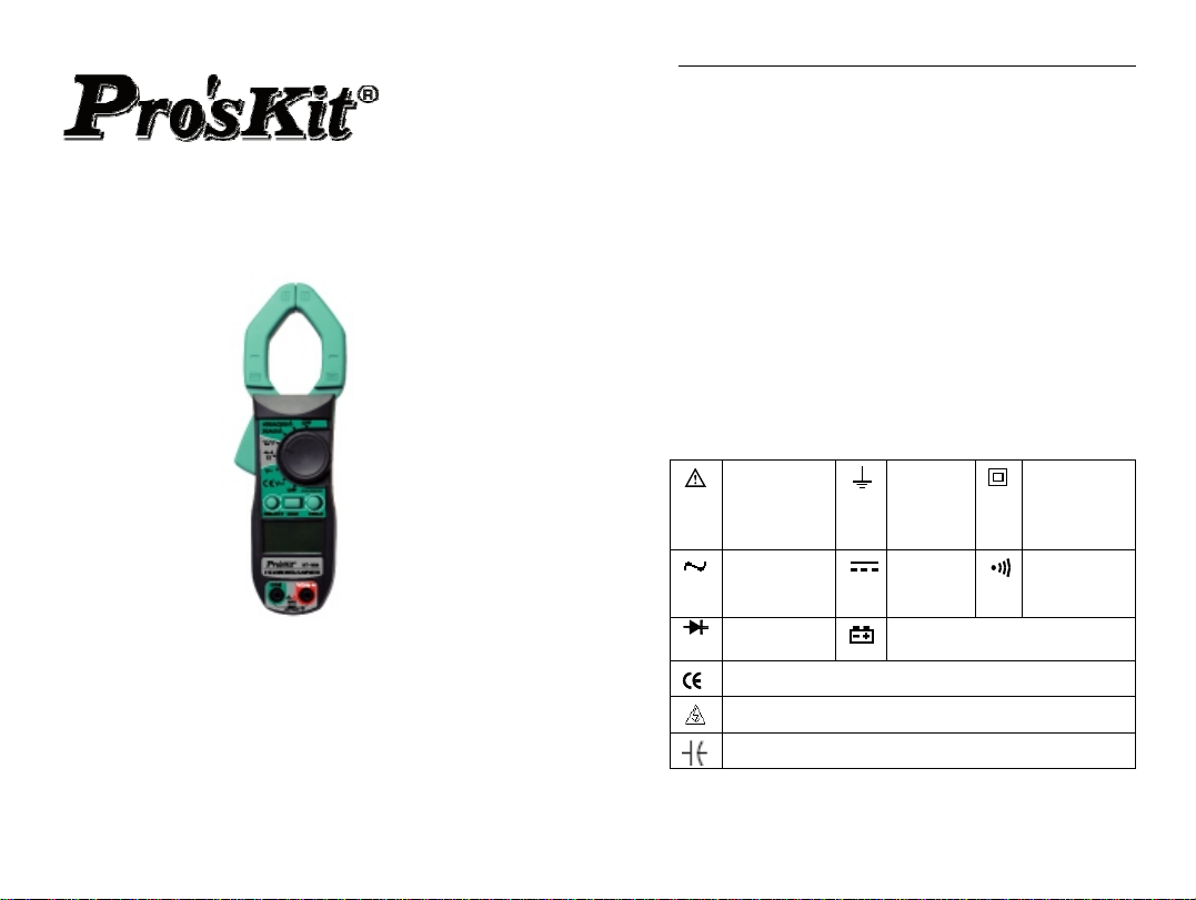
ELECTRICAL SYMBOLS
Warning
Alternating
signal test
Diode test
Conforms to European Union directives
Dangerous voltage may be present.
Capacitor
Earth
Ground
Direct
signal
test
Low Battery
1
over
Double
insulated
(Protection
class II)
Continuity
buzzer
Page 2
3 1/2 2A Mini Digital Clamp Meter user manual
r
SAFETY WARNING
1. Read the operating instructions before using the
instrument and pay particular attention to all
WARNINGS and CAUTIONS in this instruction
manual.
2. Be sure that the cover and the test leads of the
meter are in good conditions.
3. Set the range / function switch at the correct position
when measuring.
4. Make sure to insert the red and the black test leads
to their appropriate jacks. The black test lead should
be connected first when measuring while the red
test lead should be disconnected first after
measuring.
5. When the range and function changes, both test
leads should be disconnected.
6. To avoid damage to the instrument, never exceed
the allowable maximum input of each range.
7. Be care of electric shock hazard when the voltage to
be tested is above DC 60V or AC 30V.
8. To avoid electric shock, do not open the battery
compartment cover when making measurement.
9. Remove the test leads from the circuit being
measured before replacing the battery.
10. Do not change the built-in circuit to avoid damage to
the meter.
11. Do not use or store the instrument in an explosive
atmosphere (i.e. the presence of flammable gas or
fume, vapor or dust)
12. CAT II-Measurement Category II is for
measurements performed on circuits directly
connected to low voltage installation.(Examples are
measurements on household appliances, portable
tools and similar equipments.)Dot not use the meter
2
3 1/2 2A Mini Digital Clamp Meter user manual
for measurements within Measurement Categories
III and IV
13.
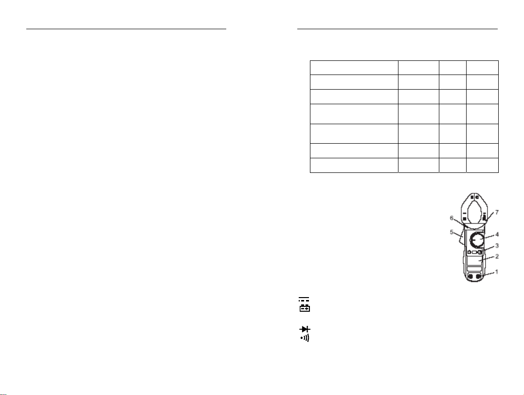
MT-3102 SELECT MAX HOLD
DC Voltage N/A ● ●
AC Voltage N/A ● ●
Resistance,
Continuity,Diode test
Temperature
℃/℉(K-Type)
● N/A ●
● N/A ●
DC current 2/20A N/A ● ●
AC current 200/400A N/A ● ●
FRONT PANEL DESCRIPTION
1. COM Input Jack / V/Ω Input Jack
2. 1/2-digit LCD Display Panel
3. Function Switch Button
(SEL/MAX/HOLD)
4. Function/range select rotary selector
5. Trigger
6. Protection edge
7. Current Clamp
LCD DISPLAY SYMBOLS
~
AUTO
HOLD
℃/℉
nating signal test
Alte
Direct signal test
Low Battery
Auto range mode ?
Diode test
Continuity buzzer
This indicates that the display data is being held
Temperature test
3
Page 3
3 1/2 2A Mini Digital Clamp Meter user manual
Ω
μm / VA
MAX
-
Ohms, Kilo-ohms, mega-ohms resistance test
Amperes(Current)or Milli-volts, Volts(Voltage)
The maximum value is being measured
Negative polar mark
GENERAL SPECIFICATIONS
1. Auto range and manual range options are available.
2. Over range protection is provided for all ranges.
3. Display:3 1/2-digit(1999 count)
4. Measuring method:Dual slope integration A/D
converter
5. Sampling speed:2-3 time/sec
6. Unit display:Function and unit symbols displayed
7. Polarity:Automatic negative polarity display
8. Overload indication:Symbol “1”appears on the LCD
9. Low battery indication:Symbol appears on the LCD
10. Auto power off time:15min
11. Operation temperature:0~40℃,≦75%RH
12. Storage temperature:-20℃~60℃, ≦75%RH
13. Operation power:1.5V x 3AAA Batteries
14. Dimension:203mm(L)x68mm(W)x33mm(D)
15. Weight:187g(without battery)
BUTTON FUNCTION AND AUTO POWER OFF
1. HOLD: For measuring data hold, press the HOLD
button, the peak value of current data will be
keeping displaying on LCD; press it again to cancel
this function
2. MAX: Maximum data hold button, when press this
button, the A/D converter will keep measuring, and
the display updating the data and hold the maximum
data
3. SELECT:Function selection button, press for
switching ohm / diode /continuity/ temperature
4
3 1/2 2A Mini Digital Clamp Meter user manual
function when tested objects change
4. Auto-power off : If there is no any operation within any
fifteen minutes after power is on, the meter will auto
power off. Turn the rotary selector or press any
function button to resume operation of the meter
under the auto power off mode. At the same time
when power on, if press the ”HOLD” button, auto
power off will be disable.
NOTE:
(1) When the meter auto power off under temperature
measuring function, and rotate the selector to any
measuring function, the meter will be able to resume
operation, except ACV measuring function.
(2) After automatic turn-off, THEN press HOLD to
re-start, the function of automatic turn-off will be
cancel.
5. Buzzer
Set the selector to any measuring function (except
2/20A ACV function), press any button, the buzzer will
sound; otherwise, the button is idleness. One minutes
before auto power off, the buzzer continue sound in
five times, and one long buzz before power off.
Note: when the selector in measuring function of
2/20A ACV, the buzzer won’t sound.
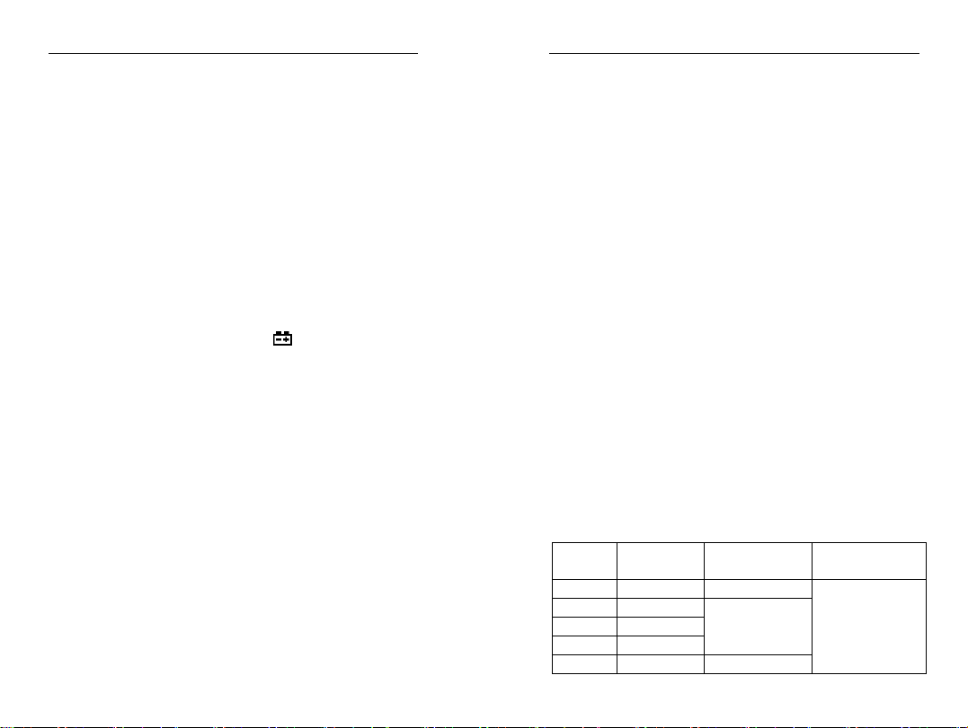
ELECTRICAL SPECIFICATIONS
Accuracy:±(%reading + digits)
Operation temperature:23 , 75%RH℃≦
Range Resolution Accuracy Overload
protection
200mV 0.1mV ±(0.8%+5d)
2V 1mV
20V 10mV
±(0.8%+3d)
600V rms
200V 100mV
600V 1V ±(1.0%+5d)
5
Page 4
3 1/2 2A Mini Digital Clamp Meter user manual
AC Voltage:Auto Range
Range Resolution Accuracy Overload
protection
2V 1mV
20V 10mV
200V 100mV
±(1.2%+5d)
600V rms
600V 1V ±(1.5%+5d)
Input impedance:10MΩ
Frequency range:40~400Hz
AC Current:Auto Range
Range Resolution Accuracy Overload
protection
±(4%+20d)
2A 1mA
0.4A≦
±(3%+15d)
20A 10mA
±(3%+15d)
0.4A≦
400A rms
±(2%+10d)
200A 0.1V
400A 1A
±(2%+5d)
Frequency range:40~400Hz
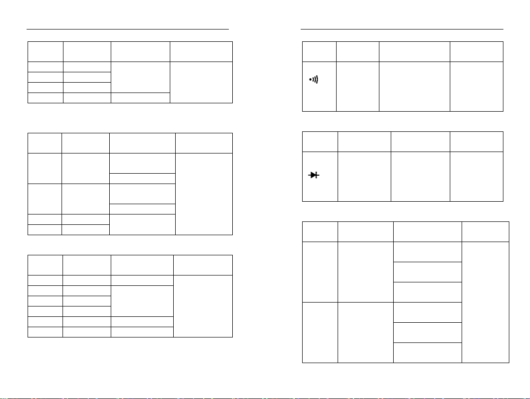
Resistance:Auto Range
Range Resolution Accuracy Overload
protection
200Ω 100mΩ ±(1.2%+5d)
2KΩ 1Ω
20KΩ 10Ω
200KΩ 100Ω
±(1%+3d)
600Vp
2MΩ 1KΩ ±(1.2%+5d)
20MΩ 10KΩ ±(1.5%+5d)
3 1/2 2A Mini Digital Clamp Meter user manual
Continuity:
Range Resoluti
on
100mΩ Built-in buzzer
Accuracy Overload
protection
will sound, if
resistance is
600Vp
lower than
50Ω≦
Open circuit voltage ~ 0.45V
Diode:
Range Resolution Accuracy Overload
protection
1mV Displaying
approximate
forward
600Vp
voltage of
diode
Open circuit voltage ~ 1.48V
Temperature: /℃℉
Range Resolution Accuracy Overload
protection
-40 ~32 ±℉℉
-40 ~℉
1832
℉
-40 ~℃
1000
℃
1℉
1℃
(3%+8d)
0 ~752 ±℉℉
(1%+6d)
752 ~1832 ±℉℉
(2%+18d)
-40~0±℃℃
(3%+4d)
0 ~400 ±℃℃
(1%+3d)
400 ~1000 ±℃℃
600Vp
(2%+10d)
6
7
Page 5

3 1/2 2A Mini Digital Clamp Meter user manual
p
g
MEASURING AC VOLTAGE
1. SAFETY INFORMATION
WARNING
Beware of Electrocution
Pay special attention to avoid electric shock when
measuring high voltage. Do not input the voltage which
more than 600V rms AC.
1. Plug the black test lead into the COM jack and the
red test lead into the V/Ω Jack.
2. Set the rotary selector to V~ position to make the
meter get into AC V range.
3. Connect the test leads to the voltage source or
load terminals for measurement.
4. Take the reading on the LCD.
MEASURING DC VOLTAGE
Beware of Electrocution
Pay special attention to avoid electric shock when
measuring high voltage.
Do not in
ut the voltage which more than 600V DC.
WARNING
1) Plug the black test lead into the COM jack and the
red test lead into the V/Ω Jack.
2) Set the rotary selector to V
position to make
the meter get into DC V range.
3) Connect the test leads to the voltage source or
load terminals for measurement.
4) Take the reading on the LCD.
MEASURING AC CURRENT
Beware of Electrocution.
Ensure that the test leads are disconnected from the
meter before making current clamp measurements.
WARNING
8
3 1/2 2A Mini Digital Clamp Meter user manual
1) Set the rotary selector to the A~2A/20A or
200A/400A range position.
2) Press the trigger to open jaw. Fully enclose only one
conductor.
3) Take the reading on the LCD.
MEASURING RESISTANCE
Beware of Electrocution.
Ensure that the test leads are disconnected from the
meter before making current clamp measurements.
WARNING
1) Plug the black test lead into the COM jack and the
red test lead into the V/Ω Jack.
2) Set the rotary selector to Ω/
/ range position to
make the meter get into AC V range.
3) Connect the test leads to the ends of the resistance
or circuit for measurement.
4) Take the reading on the LCD.
TESTING CONTINUITY
Beware of Electrocution.
Make sure that the power of the circuit has been
turned off and the capacitors have been fully
dischar
ed before testing the continuity of a circuit.
WARNING
1) Plug the black test lead into the COM jack and the
red test lead into the V/Ω Jack.
2) Set the rotary selector to Ω/
3) Press the “SEL” button to switch to
/ range position.
continuity
test.
4) Connect the test leads to the ends of the resistance
or circuit for measurement.
5) If the resistance of the circuit being tested is less
than 50Ω, the built-in buzzer will sound.
6) Take the reading on the LCD.
9
Page 6

3 1/2 2A Mini Digital Clamp Meter user manual
TESTING DIODE
1) Plug the black test lead into the COM jack and the
red test lead into the V/Ω Jack.
2) Set the rotary selector toΩ/
3) Press the “SEL” button to switch to
/ range position.
test.
4) Connect the red test leads to the anode and the
black test lead to the cathode of the diode for
testing.
5) Take the reading on the LCD.
TESTING TEMPERATURE
1) Plug the black test lead into the COM jack and the
red test lead into the V/Ω Jack.
2) Set the rotary selector to /℃℉range position.
3) Connect the red test leads to the anode and the
black test lead to the cathode of the temperature
load for testing.
4) Take the reading on the LCD.
REPLACING THE BATTERIES
To avoid electric shock, make sure that the test leads
have been clearly move away from the circuit under
measurement before opening the battery cover of the
meter.
1) If the sign
WARNING
appears, it means that the batteries
should be replaced.
2) Loosen the fixing screw of the battery cover and
remove it.
3) Replace the exhausted batteries with new one.
4) Put the battery cover back and fix it again to its
origin from.
NOTE:
Do not reverse the poles of the batteries.
10
3 1/2 2A Mini Digital Clamp Meter user manual
MT-3102 3 1/2 2A 迷你鉤錶中文說明書
一. 概述
MT-3102 是一種性能穩定,安全、可靠的 3 1/2 位元數字
鉗形表(以下簡稱鉗錶)系列。整機電路設計以大型積體
電路雙積分 A/D 轉換器為核心,全量程的超載保護電路,
獨特的外觀設計使之成為性能優越的專用電工儀錶。鉗表
可用於測量交直流電壓、交流電流、電阻、二極體電路通
斷、° C / °F 溫度等。本使用說明抬包括有關的安全資訊和
警告提示等,請仔細閱讀有關內容並嚴格遵守所有的警告
和注意事項。
警告:在使用鉗表之前,請仔細閱讀有關的安全操作準則
二.開箱檢查
打開包裝盒,取出儀錶,請仔細檢查下列專案是否缺少或
損壞:
1.使用說明書 一本
2.表筆 —付
3.溫度探頭(僅用於 MT-3102) 一個
如果發現任何一個項目缺少或損壞,請立即與您的供應商
聯繫。
三,安全操作準則
請注意“警告標識
危險、對儀錶或被測設備可能造成損壞的情況或行動。
本儀錶嚴格遵循 GB4793 電子測量儀器安全要求以及
IEC61010-I 和 LECI010-2-032 安全標準進行設計和生
產,符合雙重絕緣、過電壓 CAF 600VⅡ 、和污染等級 2
的安全標準。如果未能按照有關的操作說明使用鉗表,則
可能會削弱或失去鉗表為您提供的保護能力。
1. 使用前應檢查鉗表和表筆,謹防任何損壞或不正常的
現象。如發現本鉗表表筆、殼體絕緣已明顯損壞以及
液晶顯示器無顯示等,或者您認為本鉗表已無法正常
工作,請勿再使用本鉗表。
及警告字句”警告表示對使用者構成
11
Page 7

3 1/2 2A Mini Digital Clamp Meter user manual
2. 後蓋及電池蓋沒有蓋好前嚴禁使用鉗表,否則有電擊危
險.
3. 在進行測量時,切記手指不要超過表筆擋手部位,不要
接觸裸露的電線、連接器、沒有使用的輸入端或正在測
量的電路,防止觸電。
4. 測量前功能開關必須置於正確位置,嚴禁在測量進行中
轉換檔位,以防損壞鉗表。
5. 不要在鉗表終端及接地之間施加 600V 以上電壓,以防
電擊和損壞鉗表。
6. 當儀錶在 60V 直流電壓或是 30V 交流有效值電壓下工
作時,應小心操作,此時會有電擊的危險存在。
7. 不要測量高於允許輸入值的電壓或電流,在不能確定被
測量值的範圍時,須將功能量程開關置於最大量程位
置。進行在線電阻、二極管或電路通斷測量之前,必須
先將電路中所有電源切斷,井將所有電容器放電。測量
完畢,要斷開表筆與被測電路的連接,並從鉗表輸入端
拿掉表筆以及關斷鉗表電源。
8. 當液晶顯示器顯示
標誌時,應及時更換電池,以
確保測量精度。鉗表長期不用時,應取出電池。
9. 請勿隨意改變鉗表內部接線,以免損壞儀錶和危及安
全。
10. 不要在高溫、高濕、易燃、易爆和強電磁場環境中存放、
使用鉗表。
11. 維護保養請使用軟布及中性清潔劑清潔儀錶外殼,切勿
使用研磨劑及溶劑,以防外殼被腐蝕,損壞儀錶、危及
安全。
電氣符號︰
警告提示
AC(交流)
二極體
接地
DC(直流)
錶內電池不足
12
雙重
絕緣
蜂鳴
通斷
3 1/2 2A Mini Digital Clamp Meter user manual
符合歐洲共同體(European Union)標準
允許從危險帶電導體安裝和拆卸
電容
五、外表結構(見圖 1)
1. 輸入端。
2. 液晶數字顯示。
3. 功能按鍵,選擇基本功能。
4. 測量功能轉盤。
5. 鉗頭板機:按壓板機, 使鉗頭
張開,若鬆開板機,則鉗頭局
部再度密合。
6. 手部防護:為保護使用者手部
碰碰觸到危險區的一種安全設
計。
7. 鉗頭:為測量交流電流的一種裝置,使電流轉換為電
壓,待測電流單一導體必須穿越鉗頭中心。
六.顯示符號(見圖 2)
1. 交流信號測量;
2. 直流信號測量;
3. 電池電量不足指示;
4. 自動量程指示
5. 二極體測試指示
6. 連續檢測指示;
7. 最大值指示;
8. 資料保持指示;
9. 溫度測量單位(℃攝
氏度、℉華氏度);
10. 電阻測量單位(Ω 歐姆、KΩ 千歐、M Ω 兆歐);
11. 電流測量單位(A 安培);
12. 電壓測量單位(mV 毫伏、V 伏特);
13
Page 8

3 1/2 2A Mini Digital Clamp Meter user manual
13. 顯示負的極性;
14. 對所選量程輸入信號太高,表示溢出;
七,按鍵功能及自動關機
1.HOLD:
為讀數保持鍵,以觸發方式工作,功能為保持顯示讀數。
觸發一次此鍵,顯示值被鎖定,一直保持不變,再觸發一
次此鍵,鎖定狀態被解除,進入通常測量狀態。
注意:在自動關機後,若按著 HOLD 鍵開機,自動關機
功能將被取消。
2.MAX:
為最大值鍵,以觸發方式工作,按此鍵後,A/D 轉換器會
繼續工作,顯示值總是更新和保留最大值。
3. SELECT:
為功能選擇鍵,以觸發方式工作,用此鍵可作為
℃ / ℉的切換。
4.自動關機
在測量過程中,功能按鍵和轉盤開關在 15 分鐘內均無動
作時,鉗表會自動關機(休眠狀態),以節約電能;要取
消自動關機功能,只要按著 HOLD 鍵開機,則自動關機
功能被取消。在自動關機狀態下,按動功能鍵(有效的按
鍵操作,詳見 6.)或是轉動轉盤開關,鉗表會“自動開機”
工作狀態)。
注意:(1)在溫度測量檔(MT-3102)自動關機後,轉換到交
流電流檔則不能喚醒,轉換到其他檔能夠喚醒:
(2)在休眠狀態下按 HOLD 鍵喚醒,自動關機功能被
取消。
5.蜂嗚器
在任一測疑檔位(2/20A 電流測量檔除外)按動任意功能
按鍵,如果該鍵有效,蜂嗚器會發“嘩”的一聲,無效則不
會發聲;自動關機前約 1 分鐘蜂鳴器會連續發出 5 聲警
示;關機前蜂嗚器會以 1 長聲警示。
注意:在 2/20A1A 電流測量檔,鉗表已設定蜂嗚器不
會發聲。
14
3 1/2 2A Mini Digital Clamp Meter user manual
6.按鍵的有效性
並非所有的按鍵操作在任一檔位上都是有效的,只有有
效的按鍵操作,才能選擇相應的操作功能或喚醒休眠狀
態下的儀錶,見下表:
MT-3102 檔位元
按鈕
SELECT MAX HOLD
直流電壓 N/A ● ●
交流電壓 N/A ● ●
電阻,導通,二極體測
試
● N/A ●
溫度 /(K℃℉ -Type) ● N/A ●
交流電流 2/20A N/A ● ●
交流電流 200/400A N/A ● ●
八.測量操作說明
警告:鉗表不得用於電壓大於 600V 交流/直流導電的物
體上
1.直流電壓測量(
*設置轉盤到
)
位置
*選擇按鍵功能
*連接負載
在完成所有的測量操作後,要斷開表筆與被測電路的連
接,從輸入端拿掉表筆。
2.交流電壓測量(V~)
*設置轉盤到 V~位置
*選擇功能
*連接負載
在完成所有的測量操作後,要斷開表筆與被測電路的連
接,並從輸入端拿掉表筆。
3.電阻測量(Ω)
15
Page 9

3 1/2 2A Mini Digital Clamp Meter user manual
警告:在連接負載以前務必將電路電源切斷
*設置轉盤到 Ω 位置
*選擇功能
電阻測量為最初設定值.
*連接負載
若將元件從電路中分離出來測量可得到較好的結果。
4.二極體測量(
)
警告:在連接負載以前務必將電路電源切斷
*設置轉盤到
位置
*選擇功能
按 SLLECT 鍵選擇二極體測
*連接負載
若將元件從電路中分離出來測量可得到較好的結果。
5.導通檢測(
)
警告:在連接負載以前務必將電路電源切斷
*設置轉盤到
位置
*選擇功能
按 SELECT 鍵選擇導通檢測
*連接負載
在導通測試中測最電阻小於 50Ω 時蜂鳴器會響,
在 50Ω 到 120Ω 時蜂嗚器可能響或不響,大於 120Ω 蜂
鳴器不響。
6.溫度測量 (℃/℉)
*設置轉盤到 ℃/℉位置
*選擇功能
℃測量為最初設定值
按 SELECT 鍵可選擇℃或℉測量
*連接負載
7.電流測量(A~)
*設置轉盤到 A~位置
*選擇功能
*連接負載
將鉗表夾取待測導體,然後緩慢地放開板機,直到鉗頭
16
3 1/2 2A Mini Digital Clamp Meter user manual
完全閉合,請確定待測導體是否被夾取在鉗頭的中央,
鉗表一次只能測量一個電流導體,若同時測量兩個或以
上的電流體,測量讀數會是錯誤的。
九.技術指標
1) 一般規格
液晶濕示:3 1/2 位元液晶顯示,最大顯示至 1999.
極性顯示:自動正負極性顯示
超載顯示:以 OL 或-OL 顯示
低電壓顯示:
符號顯示電池電壓低於工作電壓,做
為更換電池的參考取樣率:3 次/秒
測試位置誤差:測量電流時因為未將待測源置於適當位
置而產生±1%讀值誤差感測器種類:AC 測量的鉗形互
感器
鉗頭開啟最大尺寸:直徑 30mm
預測電流導線最大尺寸:直徑 30mm
電源需求:三個 1.5V AAA 電池
自動關機功能(可以在使用時取消該功能)
尺寸:203mrn(寬)x68(長)x 33mm(高)
重量:約 187g (不含電池)
2) 環境限制
室內使用最大高度:2000 米
公害等級:2
操作溫濕度:O℃到 30℃(不大於 75%R.H.),30℃到 40℃
(不大於 70%R.H.),4℃到 50℃(不大於 45%R.H.)
儲存溫濕度:-20℃到±60℃(不大於 75%R.H.)
3) 電氣規格
準確度:±(%讀數十位元數),校準期為—年
環境溫度:23 ±5℃℃
環境濕度:不大於 75 % R.H .
溫度係數:0.1x 精度 / 1℃
17
Page 10

3 1/2 2A Mini Digital Clamp Meter user manual
1.交流電壓(ACV):自動量程
量程 解析度 準確度 超載保護
2.000V 0.1mV
20.00V 10mV
200.0V 100mV
±(1.2%+5)
600V rms
600V 1V ±(1.5%+5)
輸入阻抗:10MQ//小於 100pF
AC 轉換類型:正弦波輸入、平均值回應,校正讀數至與
有效值一致。
頻率回應:40Hz-1KHz
2.直流電壓(DCV):自動量程
量程 解析度 準確度 超載保護
200.0mV 0.1mV ±(0.8%+5)
2.000V 1mV
20.00V 10mV
±(0.8%+3)
600V rms
200.0V 100mV
600V 1V ±(1.0%+5)
輸入阻抗:10MΩ
3.電阻(Ω):自動量程
量程 解析度 準確度 超載保護
200.0Ω 100MΩ ±(1.2%+5)
2.000KΩ 1Ω
20.00KΩ 10Ω
200.0KΩ 100Ω
±(1%+3)
600Vp
2.000MΩ 1KΩ ±(1.2%+5)
20.00MΩ 10KΩ ±(1.5%+5)
18
3 1/2 2A Mini Digital Clamp Meter user manual
4.導通測試( )
量程 解析度 準確度 超載保護
約≦50Ω 時蜂鳴器
100MΩ
會響(開路電壓約
600Vp
0.45V)
注意:在導通測試中量測電阻在 50Ω 到 120Ω 時蜂嗚器可
能響或不響,大於 120Ω 蜂鳴器不響。
5.二極體測試()
量程 解析度 準確度 超載保護
1mV
顯示正向壓降近似值
開路電壓約 1.48V)
600Vp
6.溫度測試(℃/℉):
量程 分辯率 準確度
-40°C
~1000°C
-40°F
~1832°F
1°C
1°F
-40°C~-0°C±(3%+4)
0°C~400°C±(1%+3)
400°C~1000°C±(2%+10)
-40°F~-32°F±(3%+8)
32°F~752°F±(1%+6)
752°F~-1832°F±(2%+18)
超載
保護
600Vp
7.交流電流(ACA):自動量程
量程
2.000A 1mA
20.00A 10mA
200.0A 0.1A
400A 1A
解析
度
準確度 頻率回應
±(4%+20) 0≦ .4A
±(3%+15)
±(3%+15) 4A≦
±(2%+10)
±(2%+5)
19
50Hz~60Hz
超載
保護
400A
rms
Page 11

3 1/2 2A Mini Digital Clamp Meter user manual
十.保養和維護
警告:在打開底蓋前為避免電擊,請移開測試棒。
1.一般維護
a.本鉗表的維修與服務必須由有資格的專業維修人員或
指定的維修部門完成。
b.定期性使用乾布去清潔外殼,但不得使用含有研磨妝或
溶劑成份的清潔劑。
2.電池安裝或更換
本產品的電力為三顆 1.5V AAA 電池,按下列順序安裝
或更換電池。
a.本產品關機,請移開位於輸入端之測試棒。
b.將本產品面板朝下,並旋開電池盒螺絲,拔下電池蓋。
c.從電池倉上取下舊電池,按照極性指示安裝新電池。
d.請使用同一型號的從 A 電池,不要安裝不適當的電池,
新舊以及不同型號的電池不能混裝使用。
e.安裝新的電池後,裝上包池蓋,並鎖上螺絲即可。
3 1/2 2A Mini Digital Clamp Meter user manual
Certificate Number: TW98/12323QA
20
21
 Loading...