

Page 1

Professional Digital
Multimeter
DC
AUTO
APO
MAX/MIN Hz/DUTY H
AUTO POWER OFF
POWE
R
C
A
/
C
D
m
A
10A
mA
10A
10sec MAX
FUSED
Ω
600mA
FUSED
MAX
OLD RANGE
H
z
/
C
˚/
F
˚
A
COM
CAT ll
REL/RS232
TEMP
VΩ Hz
MAX
1000V D
750V
V
C
AC
MT-1860
U s e r ’ s M a n u a l
Page 2

Contents
General 2
Open-package Inspection 2
Safety Note 2
Description of Safety Symbols 3
Description of Instrument Panel and Push button Functions 4
Other Functions 5
Property 5
DC Voltage (DCV) 6
AC Voltage (ACV) 7
DC Current (DCA) 8
AC Current (ACA) 10
Resistance 11
Diode and On-and-Off Test 12
Capacitance (C) 13
Temperature Measurement 14
Communication Connection 15
Instrument Maintenance 16
1
Page 3

General
MT-1860 endowed with the key touching function instead of the traditional mechanical
knobs, is a new type of 3 5/6 digital multimeter equipped with the LCD display device
with the text height of 33mm which has the merits of visual display, easy operation, stable
performance and high reliability. It can be used to measure DC voltage, AC voltage, DC
current, AC current, resistance, capacitance, frequency, temperature, diode and make
on-and-off test. Meanwhile, it is available for unit symbol display, data retention, the mea-
surement of maximum and minimum value, automatic/manual range switching, automatic
power off and alarm function. The complete machine takes a switching integrated circuit
which can directly drive LCD microprocessor and double-integrating A/D and a digital
display drive offering high resolution and high precision. Due to it’s complete functions,
high measurement accuracy and convenient operation, the multimeter is the ideal tool in
laboratory and factory as well as for radio fans and family.
Open-package Inspection
Open the package box and take out the meter, check carefully if the following accessories
are absent or damaged. If there is any absence or damage, please contact the distributor
immediately.
Digital Multimeter 1 PC
Instruction Manual 1 copy
Test Leads 1 pair
Temperature Probe (K-Thermocouple) 1 PC
PC Interface Cable 1 PC
Software Disk 1 PC
Holster 1 PC
Safety Note
In accordance with IEC1010 clause (the safety standard issued by International Elec-
trotechnical Commission), MT-1860 is designed and produced according to the safety
requirements of pollution level II.
Warning:
In order to avoid endangering the operator’s safety, prior to the operation of the instru-
ment, please read the instruction manual carefully, and conform to the safety warning
information and operation instruction strictly to use the instrument.
1. When voltage above 30V, current above 10mA, AC power line with inductive load or
power line during electric uctuation is measured, please beware of electric shock.
2. Prior to measurement, check if the measurement function is in conformity with the
2
Page 4

LCD display, and if the push button switch is at the trigger position. Check if the
meter pen is contacted reliably, connected correctly, and grounded well and etc. In
order to avoid electric shock.
3. Only if the meter is used with the matched meter pen, can it meet the requirement
of safety standard. When the line of the meter pen is damaged, it is necessary to
replace another one of the same model or the same electrical specication.
4. Don’t use other unconrmed or disapproved protector tube to replace the protector
tube inside the meter. Only the protector tube of the same model or same specica-
tion can be replaced. Before the replacement, the meter pen must leave the measur-
ing point and ensure there is no any signal at the input terminal.
5. Don’t use other unconrmed or disapproved battery to replace the battery inside the
meter. Only the battery of the same model or same electrical specication can be
replaced. Before the replacement, the meter pen must leave the measuring point and
ensure there is no any signal at the input terminal.
6. When the electrical measurement is made, never let your body get in touch with the
ground directly, and don’t touch uncovered metal terminal, output port, lead clamp
and etc. Where earth potential may exist. Dry clothes, rubber shoes, rubber cushion
and other insulating material are usually used to keep your body insulated against
the ground.
7. Don’t store and use it in the high-temperature, high-humidity, inammable and strong
magnetic eld environment.
8. It may do damage to the meter and endanger the operator’s safety if the voltage
value beyond the permitted ultimate voltage value is measured. The ultimate voltage
value permitted for measurement is marked on the instrument panel, and never
measure the value exceeding the standard. Don’t input the ultimate value out of
regulation in order to avoid electric shock and the damage to the meter.
9. When the meter pen is inserted into the current socket, don’t measure any voltage for
fear that the meter should be damaged and the operator’s safety be endangered.
10. Don’t try calibrating or repairing the meter. When it is indeed necessary for that, only
the qualied professional personnel who have had special training or gained approval
can make it.
11. During measurement, the requirement of measurement function must be in accor-
dance with LCD display. Please be sure to disconnect the line of the meter pen with
the measured object rst and ensure there is no any input signal. It is forbidden to
switch the function/range selection switch during measurement
12. When “ ” is shown on LCD display, please replace battery immediately to
ensure the measurement precision.
13. It is not allowed to insert the meter pen into the current terminal to measure voltage!
3
Page 5
14. Please don’t change the circuits of the meter freely for fear that the meter be dam-
aged and the safety be endangered.
Description of Safety Symbols
Warning! Battery Under voltage
High Voltage! Danger! AC/DC
Ground In accordance with the instructions
of European Trade Union
Double Insulation Fuse
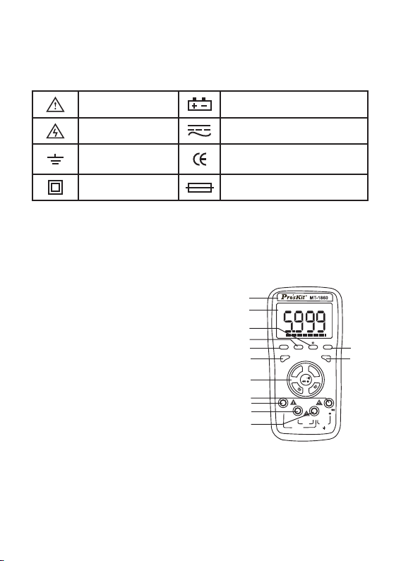
Description of Instrument Panel and Push button Functions
1. Instrument model.
2. LCD display area.
3. Function button: Used to select various
measurement functions.
3-1 “Hold” backlight switch and reading-keeping
switch. If the switch is pressed over 2 seconds,
the backlight turns on. Further press the switch
over 2 seconds, the backlight turns off or
automatically turns off after 10 seconds.
Pressing the switch within 2 seconds could lock
or unlock the data retention. Press the switch
once to lock and press it again to unlock.
3-2 Hz/DUTY: Press the key in the gear of
frequency can switch between the frequency
and the Duty Cycle.Press the key in the gear
of AC Voltage or AC Current can switch among
1
DC
2
3-1
AUTO
APO
3-2
3-3 3-4
MAX/MI
4
POWE
4
6
7
10A
8
9
N H
R
z/DUT
Y HOLD RANGE
AUTO POWER OFF
C
A
/
C
D
Ω
m
A
mA
MAX
600mA
FUSED
10A
X
10sec MA
FUSED
V
REL/RS232
H
z
/
C
˚/
F
˚
A
TEMP
VΩ Hz
COM
MAX
1000V DC
750V AC
T ll
CA
the voltage, current, frequency and duty cycle.
3-3 MAX/MIN: The maximum value and minimum value.
Press the function button and enter MAX mode, in which the maximum value is held;
press the button again to enter MIN mode, in which the minimum value is held. After
the MAX/MIN mode is entered, the display device indicates the MAX/MIN value. No
analog bar display and auto power off function in this working environment. Press
4
3-5
Page 6

down MAX/MIN button for 2 seconds, and then exit from MAX or MIN test.
3-4 Range: Automatic/Manual Range Switch. Pre-set it to automatic range when the
device starts up, then switch it to manual range. In the mode of manual range, press
the “RANGE” button once, it will skip to the previous shift. When it goes to the highest
shift, it goes back to the lowest shift when the button is pressed again. The procedure
repeats again in the same order. Press the button over 2 seconds, it will exit from
manual range and enter the state of automatic range measurement.
3-5 REL: Relative Value Measurement. Press this key to show the relative value
measurement, press again to cancel the relative value measurement. The procedure
repeats in the same order. Press this key over 2 seconds, it will switch to RS232,
which can be showed on the LCD screen and the RS232 data transmission is thus
open. Further press the key over 2 seconds, the RS232 icon disappears on the LCD
screen. Now the RS232 data transmission terminates. The procedure repeats.
4. “POWER” is the power switch.
5. Function Selection Button.
6. Input Port: Measure the positive input terminal of voltage, frequency, re-
sistance, capacitance, diode as well as on-and-off test, and insert red meter pen.
7. 10A current input jack: Measure the positive input terminal of 10A shift AC/DC
current, and insert red meter pen.
8. mA input port: Measure the positive input terminal of AC/DC.
9. COM input port: Measure the negative input terminal, and insert black meter
pen.
Other Functions
1. Automatic power off
After the meter is stopped for 15 minutes, it will cut off power automatically (power off),
and then enter the dormant (power off) state. The built-in buzzer will send out warning
tone in one minute before it powers off. If you want to restart power (power on), please
press the power switch. If you want to cancel automatic power-off, please press “REL”
key over 2 seconds until the RS232 symbol appears. Meanwhile the “APO” symbol will
be also turned off.
Property
1. General features
1-1. Display mode: LCD
1-2. Maximum display: 5999.3 5/6 display automatic polarity display and unit display.
5
Page 7

1-3. Analog bar. 30 times/sec, display of 61 analog bars.
1-4. Measurement mode: dual integration A/D conversion.
1-5. Sampling rate: About 3 time/sec.
1-6. Over range: Display “OL”
1-7. Low voltage display: about 2.4v, the symbol displayed.
1-8. Working temperature: 0~40˚C
1-9. Storage temperature: -10~50˚C, relative humidity <80%
1-10. Power: Two 1.5v batteries (“AAA” batteries)
1-11. Volume (Dimensions): 185mm×91mm×49mm (Length x width x height)
1-12. Weight: About 410g (including battery )
2.Technical features
2-1. Accuracy: ±(a% reading + d digits), the ambient temperature for ensuring accuracy:
23±5˚C, relative humidity <75%.
2-2. The warranty period of calibration is one year from ex-factory date.
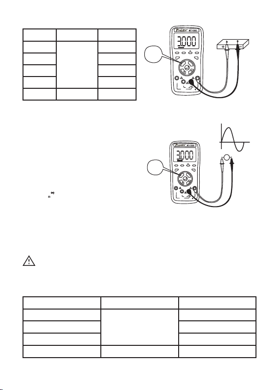
DC Voltage (DCV)
1. Press “AC/DC”, select automatic measurement of DC voltage., and respectively plug
in the red and black meter pens into the terminals of “VΩHz” and “COM”, as shown in
the following diagram.
2. The initial state of the meter is the DC voltage automatic measurement mode, which
shows the symbols of “DC” “AUTO” “APO”. Press “RANGE” is to select manual range
mode; Press “MAX/MIN” once to show the Max measurement value. Press “MAX/MIN”
again to show the Min measurement value. Press “MAX/MIN” over 2 seconds is to
cancel the measurement of the MAX/MIN value.
3. Touch the measuring point with the meter measuring pen and connect it in parallel to
the circuit being tested, and the polarity of the red meter pen wire and the tested volt-
age value are spontaneously displayed on the display.
Caution:
a) Voltages over DC1000V or AC750V cannot be tested.
b) When measuring high voltages, special precautions must be taken to avoid
electrical shock. When measurement is completed, immediately disconnect the meter
pen and the measured circuit.
c) In case “OL” is displayed for manual range mode, it indicated the range has been
exceeded and it is necessary to select higher range mode to complete this measure-
ment.
6
Page 8
Voltage
switch
DC
AUT
O
APO
MAX/MIN Hz/DUTY HOLD RANGE
AUTO POWER OFF
POWE
R
C
A
/
C
D
Ω
m
A
10A
mA
MAX
600mA
FUSED
A
10
10sec MAX
FUSED
V
REL/RS232
H
z
/
C
˚
/
F
˚
A
TEMP
VΩ Hz
COM
MAX
1000V DC
750V AC
CA
T ll
Range Accuracy Resolution
600mV
6V 1mV
60V 10mV
±(0.5%+4d)
0.1mV
600V 100mV
1000V ±(1.0%+4d) 1V
• Input impedance: 600mV range>60MΩ, the others are 10MΩ. Overload protection:
1000VDC or 750V alternative peak.
AC Voltage (ACV)
y
1. Circularly press the “AC/DC” key until
it selects the AC Voltage automatic
measurement mode. Meanwhile, the
symbol “AC”,“AUTO”,“APO” will appear
on the LCD. Respectively plug in the
red and black meter pens into the terminals
TEMP
of “
” and “com”. See the picture re below.
VΩ H
2. The initial state of the meter is automatic range,
z
which shows “AUTO” symbol. Press the “Range” key and switch it to manual range
mode. In the AC mode of automatic/manual range, the frequency/ duty cycle can be
measured by pressing “Hz/DUTY”. However, the frequency response now is low ,
which is suitable for the measurement of high voltage and low frequency in the envi-
ronment of magnetic eld interference such as 220V/50Hz-400Hz,380V/50Hz-400Hz.
Voltage
switch
DC
AUTO
APO
MAX/MIN Hz/DUTY HOLD RANGE
AUT
O POWER OF
POWER
C
A
/
C
D
Ω
m
A
10A
mA
MAX
600mA
FUSED
10A
10sec MAX
D
FUSE
V
F
REL/RS232
H
z
/
C
˚
/
F
˚
A
TEMP
VΩ Hz
COM
MAX
1000V DC
750V AC
T ll
CA
V~
Caution:
Voltages over DC1000V or AC750V cannot be tested. In case “OL” is displayed for
manual range mode, it indicated the range has been exceeded and it is necessary to
select higher range mode to complete this measurement.
Range Accuracy Resolution
6V
60V 10mV
±(0.8%+10d)
600V 100mV
750V ±(1.0%+6d) 1V
1mV
X
60Hz
7
Page 9
• Input impedance: 10MΩ.
• Overload protection: 1000VDC or 750V alternating peak.
• Display: Mean value response (calibrated with sine wave).
• Frequency response: (40-400)Hz.
• Duty Cycle Display: (0.1%-99.9%).
DC Current (DCA)
1. Press the “ mA “ button or “ A “ button.
Plug the black meter pen into the terminal of
“COM” and the red meter pen into the terminal
of “mA” or “10A”. See the picture below.
2. Circularly press the “ mA “ button or
“ A “ button. Select automatic DC 600mA
and 10A current to test. The “DC”,“AUTO”,
DC
V
AUTO
APO
MAX/MIN Hz/DUTY HOLD RANGE
mA
AUTO POWER OFF
R
POWE
REL/RS232
H
C
z
/
A
C
/
˚
C
/
F˚
D
Ω
m
A
A
TEMP
A
10
z
VΩ H
mA
COM
MAX
MAX
600mA
1000V DC
FUSED
10A
750V AC
10sec MAX
FUSED
CAT ll
“APO” symbols will appear on the LCD screen.
3. In case “OL” is displayed on the display, it indicates the current being measured has
exceed the current range, and please select higher ranges for measurements.
Caution:
a) At the 10A mode, current bigger than 10A
cannot be measured, and at mA mode,
the current bigger than 600 mA cannot be
measured. Otherwise this will lead to the
burning of the fuse or damage the instrument.
b) When the meter pen is plugged in the
input terminal of the current, it is strictly
A
switch
DC
AUTO
APO
MAX/MIN Hz/DUTY HOLD RANGE
AUTO POWER OFF
POWER
H
C
/
A
C
D
Ω
m
A
A
10
mA
MAX
600mA
FUSED
10A
10sec MAX
FUSED
V
REL/RS232
z
/
C
/
F
˚
˚
A
TEMP
z
VΩ H
COM
MAX
1000V DC
750V AC
CAT ll
prohibited to have the meter pen connected
in parallel on any circuits.
Range Accuracy Resolution
60mA
600mA 100μA
6A
10A 10mA
±(1.0%+10d)
±(1.2%+10d)
10μA
1mA
• The maximum input current: 10A (not exceeding 15s))
• Overload protection: 0.6A/250V fuse; 10A/250V fuse.
8
Page 10

AC Current (ACA)
1. Press the “ mA “ button or “ A “ button. Plug the black meter pen into the hole of
“COM” and the red meter pen into the hole of “mA ” or “10A”. See the picture below.
2. Circularly press the “ mA “ button or “ A “ button. Select automatic AC 600aA
and 10A current to test. The “AC”,“AUTO”,“APO” symbols will appear on the LCD
screen.
3. In case “OL” is displayed on the display, it indicates the current being measured has
exceed the current range, and please select higher ranges for measurements.
Caution:
a) At the 10A mode, current bigger than 10A cannot be measured, and at mA mode, the
current bigger than 600 mA cannot be measured. Otherwise this will lead to the burn-
ing of the fuse or damage the instrument.
b) When the meter penis plugged in the input terminal of the current, it is strictly prohib-
ited to have the meter pen connected in parallel on any circuits.
Range Accuracy Resolution
60mA
±(1.5%+10d)
600mA 100μA
6A
±(2.5%+15d)
10A 10mA
10μA
1mA
• The maximum input current: 10A (not exceeding 15s))
• Overload protection: 0.6A/250V fuse; 10A/250V fuse.
• Frequency response: 40~400Hz.
• Duty Cycle Display: (0.1%-99.9%).
mA
switch
A
switch
DC
AUTO
APO
MAX/MIN Hz/DUTY HOLD RANGE
AUTO POWER OFF
POWER
C
A
/
C
D
m
A
10A
mA
10A
10sec MAX
FUSED
DC
AUTO
APO
MAX/MIN Hz/DUTY HOLD RANGE
AUTO POWER OFF
POWER
H
C
/
A
C
D
Ω
m
A
10A
mA
MAX
600mA
FUSED
10A
10sec MAX
FUSED
V
REL/RS232
H
z
/
C
˚
/
F
˚
Ω
A
TEMP
VΩ Hz
COM
MAX
MAX
600mA
1000V DC
FUSED
C
750V A
T ll
CA
V
REL/RS232
z
/
C
/
F
˚
˚
A
TEMP
VΩ Hz
COM
MAX
1000V DC
750V AC
CAT ll
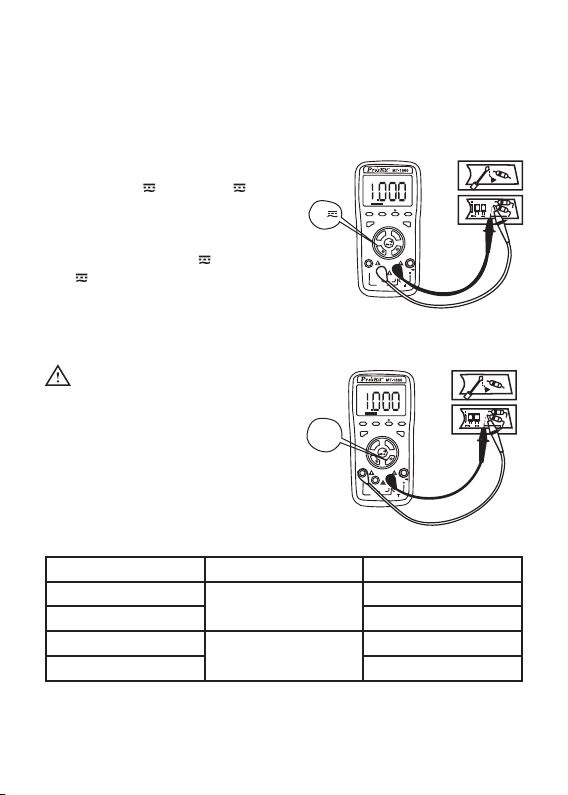
Resistance
1. Press “ Ω “ button, and respectively plug the red and black meter pens into the holes
TEMP
of “
”and “COM”.
VΩ H
z
2. Circularly press “ Ω “ button and select resistance measurement. Meanwhile, a cor-
9
Page 11

responding symbol will appear on the LCD screen. In automatic resistance measure-
ment mode, you could select manual measurement by pressing “Range”.
Caution:
a) When measuring the capacity, all the
powers within the tested circuits must
be disconnected and the capacitance
shall be sufciently discharged.
b) When measuring the resistance, any
occurrence of voltage may Lead to
inaccurate readings, and if the 250V
protection voltage is exceeded, it may
damage the meter or threaten the safety of the user.
c) When the range of 600Ω is in use, rst sort-circuit the meter pens and measure the
resistance of the lead wires and then deduct it in the actual measurement.
Range Accuracy Resolution
600Ω ±(0.8%+5d) 0.1Ω
6kΩ
60kΩ 10Ω
600kΩ 100Ω
±(0.8%+4d)
6MΩ 1kΩ
60MΩ ±(1.2%+10d) 10kΩ
• Open circuit voltage: 600mV.
• Overload protection: 250V DC or AC peak values.
resistance
switch
DC
AUTO
APO
MAX/MIN Hz/DUTY HOLD RANGE
POWER
10A
1Ω
m
10sec MAX
AUTO POWER OFF
A
/
C
D
A
mA
10A
FUSED
V
REL/RS232
H
C
z
/
C
˚/
F
˚
Ω
A
TEMP
VΩ Hz
COM
MAX
MAX
600mA
1000V DC
FUSED
750V AC
CAT ll
Diode and On-and-Off Test
1. Press “ Ω ” button and respectively plug the red and black pens into “
TEMP
VΩ H
z
”and
“ COM ”.
2. Circularly press “ Ω ” button to select the diode or buzzer measurement. In Diode
mode, LDC screen displays “ V “ and voltage symbol, and the buzzer symbol “ Ω “
is also displayed on the screen.
3. Connect the red meter pen to the positive of the diode, the black meter pen to the
negative of the diode.
Caution:
a) In case the diode is open circuit or the polarities are connected reversely, “OL” will
10
Page 12

be displayed on the screen.
b) When checking the diode, all the powers within the tested circuits must be discon-
nected and the capacitance shall be sufciently discharged.
c) When the measurement is completed, immediately disconnect the meter and the
measured circuit.
Range Display value Measurement condition
Diode forward voltage drop Forward DC current is about
If Buzzer emits a long sound and the
resistance of the two points is measured
as 30Ω
1.0mA, and backward voltage
is about 3.0V.
Open circuit voltage is about
1.2V
• Overload protection: 250V DC or AC peak value.
diode
switch
DC
AUTO
APO
MAX/MIN Hz/DUTY HOLD RANGE
AUTO POWER OFF
POWER
H
C
A
/
C
D
Ω
m
A
10A
mA
MAX
600m
A
FUSED
10
A
10sec MAX
FUSED
V
REL/RS232
z
/
C
˚/
F˚
A
TEMP
VΩ Hz
COM
MAX
1000V DC
750V AC
CAT ll
buzzer
switch
DC
AUTO
O
AP
MAX/MIN Hz/DUTY HOLD RANGE
AUTO POWER OFF
POWER
C
A
/
C
D
Ω
m
A
10A
mA
MAX
600mA
FUSED
10A
10sec MAX
FUSED
V
REL/RS232
H
z
/
C
˚/
F˚
A
TEMP
VΩ Hz
COM
MAX
1000V DC
750V AC
T ll
CA
Capacity (C)
1. Press “ Ω “ button and respectively plug in the red and black meter pens into
TEMP
“ VΩ H
” and “COM”.
z
2. Circularly press “ Ω “ button and select the automatic measurement range of
capacity. Meanwhile, the corresponding symbol will appear on the LCD screen. No
manual measurement range and analog bar will be displayed in Capacity mode
Caution:
a) When measuring the capacity, all the powers within the tested circuits must be discon-
nected and the capacitance shall be sufciently discharged
b) When measuring big capacitors, it takes a longer time, about 100uF per 15 seconds.
c) When the measurement is completed, immediately disconnect the meter and the
measured circuit.
11
Page 13

Range Accuracy Resolution
40nF ±(5.0%+30d) 10pF
400nF
4μF 1nF
±(3.5%+8d)
100pF
40μF 10nF
200μF ±(5.0%+10d) 100nF
• Overload protection: 250V DC or AC peak value.
capacitance
switch
DC
AUTO
APO
MAX/MIN Hz/DUTY HOLD RANGE
TO POWER OFF
AU
POWE
R
C
A
/
C
D
Ω
m
A
10A
mA
MAX
600mA
FUSED
10A
10sec MAX
FUSED
V
REL/RS232
H
z
/
C
˚/
F˚
A
TEMP
VΩ Hz
COM
MAX
1000V DC
750V AC
CAT ll
+ -
4.7µF
25V
Frequency (Hz)
1. Press “ Hz/˚C/˚F “ button to conduct frequency measurement.
Respectively plug in the meter pen into “ VΩHz ” and “ COM ”.
2. Have the testing end of the meter pen connected in parallel with the signal sources
to be measured and read the results from the display. (Note: No analog bar will
displayed in this mode)
3. When testing frequency, press “Hz/DUTY” once to conduct duty cycle measurement.
Press “Hz/DUTY” once more to enter the frequency status.
4. Read the current results from the display.
Caution:
a) Do not input signals higher than 60V, otherwise it may damage the instrument and
pose dangers to human safety.
b) After all the measurements are completed, it is necessary to disconnect the meter pen
and the tested circuit.
Range Accuracy Resolution
10Hz
0.001Hz
100Hz 0.01Hz
1000Hz 1Hz
10kHz 10Hz
±(0.3%+2d)
100kHz 100Hz
1MHz 1kHz
20MHz 10kHz
frequency
switch
DC
AUTO
APO
MAX/MIN Hz/DUTY HOLD RANGE
AUTO POWER OFF
POWER
H
C
A
/
C
D
Ω
m
A
10A
mA
MAX
600mA
FUSED
10A
10sec MAX
FUSED
z
/
C
A
COM
y
1KHz
V
REL/RS232
˚
/
F
˚
TEMP
VΩ H
z
MAX
1000V DC
AC
750V
CA
T ll
V~
X
12
Page 14

• Input sensitivity: 1.5V effective value. Overload protection: 250VDC or alternating peak
Temperature Measurement
1. Press “ Hz / ˚C /˚F “ button over 2 seconds, select temperature mode for celsius mea-
surement. Meanwhile, the temperature symbol will be displayed. Further press “Hz /
˚C /˚F “ , it will be displayed as Fahrenheit. The procedure repeats in the same order.
To exit from temperature measurement, press “Hz / ˚C /˚F “ button over 2 seconds.
2. Respectively plug the positive input end and negative insertion end of temperature
probe into the terminals of “
3. Put the induction end of temperature probe on the surface of the tested object.
TEMP
VΩ H
z
“ and “ COM”.
See the picture on the right.
4. Read the current testing results from the display.
Caution:
a) When the input end is open circuit,
it indicates normal temperature.
b) Do not change the temperature
sensor at random, otherwise the accuracy
of measurement can not be guaranteed.
c) Do not input voltage in temperature mode,
otherwise the meter may be damaged.
Range Accuracy Resolution
-20˚C~400˚C ±(1.0%+50d) 0.1˚C
400˚C~1000˚C ±(1.5%+15d) 1˚C
0˚F~1832˚F
±(1.0%+50d)<750˚F 0.1˚F
±(1.5%+15d)≥750˚F 1˚F
temperature
switch
DC
AUTO
APO
MAX/MIN Hz/DUTY
R
POWE
A
10
temperature
switch
˚F
V
E
HOLD RANG
AU
TO POWER OFF
REL/RS232
H
C
z
/
A
C
/
˚
C
/
F
D
˚
Ω
m
A
A
TEMP
VΩ Hz
mA
COM
MAX
MAX
600mA
1000V DC
FUSED
10A
750V AC
10sec MAX
FUSED
CAT ll
DC
V
AUTO
APO
MAX/MIN Hz/DUTY HOLD RANGE
AU
TO POWER OFF
R
POWE
REL/RS232
H
C
z
/
A
C
/
˚/
C
F
D
˚
Ω
m
A
A
TEMP
A
10
z
VΩ H
mA
COM
MAX
MAX
600m
A
1000V DC
FUSED
10
A
750V
AC
10sec MAX
FUSED
CAT ll
• K-Thermocouple (Nickel-chromium - nickel silicon) banana probe.
Communication Connection
1. Select setup to conduct installation according to the corresponding instrument models
indicated by the disk in the package.
2. Connect the instrument to computer by USB cable.
3. Press “RS232/REL” over 2 seconds and the “RS232/REL” symbol will be displayed
on screen.
4. Once the testing data is transmitted to computer, you could start recording, analyzing,
processing and printing the data. For more details, please kindly refer to instructions
in the software.
13
Page 15

Instrument Maintenance
This instrument is a sophisticated instrument and the user shall not modify the electric
circuit at will.
1. Cautions should be taken to water prevention, dust-prevention and fall prevention.
2. It shall not be stored in such environments as high temperature, high humidity and
strong electromagnetic eld.
3. Please use wet cloth and mild detergent to clean the exterior of the instrument and do
not use such strong solvents as abrasives and alcohol.
4. In case it is not used for a prolonged period of time, the battery shall be removed so as
to avoid the battery leakage from corroding the instrument.
5. Pay attention to the status of battery use, and when the LCD displays a ashing “ “
symbol, the battery shall be replaced.
The steps are as follows:
1. Loosen the screw on the back cover that secures the battery door and exit the battery
door.
2. Remove the 3V batteries and replace them with two new ones. Although a 3V battery
of any standard can be used, but in order to lengthen the service life, alkaline batteries
should be used.
3. Mount the battery door and tighten the screw;
4. Replacement of fuse: The steps are as the above. When replacing the fuse, please
use the fuse of the same size and type.
Precaution:
1. Do not connect DC or AC peak voltages higher than 1000V.
2. Don not measure voltage value on the current mode, resistance mode, diode mode
and buzzer mode.
3. When the battery has not been mounted properly or the back cover has not been
tightened, please do not use this meter.
4. Prior to the replacement of battery or fuse, please remove the measuring pen from the
measuring point and switch off the meter.
• This Instruction is subjected to change without any further notice.
• The content of this Instruction is considered correct, and in case readers nd any errors
and missing parts, please contact the manufacturer.
• The Company shall not be held liable for any accidents and hazards resulted from the
mal-operations by the user.
• The function elaborated by this Instruction shall not be taken as the reasons for using
the product for special purpose
14
Page 16

目 錄
概述 1
開箱檢查 2
安全注意事項 3
安全符號說明 5
儀錶面板及按鍵功能說明 6
其他功能 8
特性 9
直流電壓(DCV) 10
交流電壓(ACV) 11
直流電流(DCA) 12
交流電流(ACA) 13
電阻 14
二極體及通斷測試 15
電容(C) 16
頻率(Hz) 17
溫度測量 18
通迅連接 19
儀錶保養 20
15
Page 17

一.概述
MT-1860是一種新型的數位多用表,用按鍵觸發的方式代替傳統的機械旋鈕方式、顯示直
觀、操作方便、性能穩定、高可靠性、3 5/6數位多用表,儀錶採用33mm字高LCD顯示
器,可用來測量直流電壓、交流電壓、直流電流、交流電流、電阻、電容、頻率、溫度、二
極體及通斷測試,同時還有單位符號顯示、資料保持、最大最小、測量,自動/手動量程轉
換、自動斷電及報警功能。整機採用了一個能直接驅動LCD微處理器和雙積分A/D轉換積體
電路,一個提供高分辨力、高精度的數位顯示驅動,該表功能齊全,測量準確度高,使用
方便,是實驗室、工廠、無線電愛好者及家庭的理想工具。
二、開箱檢查
打開包裝箱取出儀錶,仔細檢查以下附件是否缺少或損壞,如有缺少或損壞請立即與經銷
商聯繫。
數字多用表 一台
使用說明書 一本
表筆 一付
溫度探頭( K型熱電偶 ) 一條
PC介面電攬 一根
軟體光碟 一張
防震套 一個
合格證 一張
皮盒 一個
三、安全注意事項
MT-1860符合IEC1010條款(國際電工委員會頒佈的安全標準)。使用污染等級Ⅱ的安全
要求進行設計和生產。
警 告:
為避免危及使用者的安全,在使用儀錶之前請仔細閱讀本使用手冊,並嚴格遵守安全警告資
訊和操作說明來使用本儀錶。
1. 在測量30V以上電壓,測量10mA以上電流,測量帶電感負載的交流電力線,測量電力波
動期間的交流電力線時, 謹防電擊。
2. 測量前,檢查測量功能是否與LCD上顯示相符,按鍵開關是否置觸發,要檢查表筆是否
可靠接觸,是否正確連接、是否絕緣良好等,以避免電擊。
3. 儀錶只有和所配備的表筆一起使用才符合安全標準要求。如表筆線破損時,必須更換上
同樣型號或者相同電氣規格的表筆線。
4. 不要使用其他未經確認或未認可的保險管來更換儀錶內部的保險管。只能換上同樣型
16
Page 18

號或相同規格的保險管。更換前,表筆必須離開被測量點,確保輸入端無任何信號。
5. 不要使用其他未經確認或未認可的電池來更換儀錶內的電池。只能換上同型號或相同
電氣規格的電池。更換前,表筆必須離開被測量點,確保輸入端無任何信號。
6. 在進行電氣測量時,身體切勿直接接觸大地,不要接觸可能存在地電勢裸露的金屬端
子、輸出口、引線夾等。通常使用乾燥的衣服、膠鞋、膠墊以及其他絕緣材料,保持你
的身體與大地絕緣。
7. 不要在高溫、高濕、易燃、易爆和強磁場環境中存放及使用。
8. 測量超過儀錶所允許的極限電壓值有可能損壞儀錶和危及使用者的安全。在儀錶面板
上標有儀錶所允許測量的極限電壓值,切勿測量超過此標準的安全值,請勿輸入超過規
定的極限值,以防電擊和損壞儀錶。
9. 當表筆線插入電流插座時切勿測量任何電壓以免損壞儀錶和危及使用者的安全。
10. 不要嘗試校準或維修儀錶。的確有需要時必須有專門培訓或認可的有資格專業人員才
能進行。
11. 在測量時,待測功能要求必須與LCD顯示一致,,請一定要先將表筆線與被測物件斷
開,確保輸入端沒任何信號輸入。嚴禁在測量進行中轉換功能/量程選擇開關。
12. 當LCD顯示“ ”時,請及時更換電池以確保測量精度。
13. 不允許表筆插在電流端子去測量電壓!
14. 請不要隨意改變儀錶線路,以免損壞儀錶和危及安全。
四、安全符號說明
警告! 電池欠壓
高壓!危險! 交直流
大地 符合歐洲工會指令
雙重絕緣 保險絲
17
Page 19

五、儀錶面板及按鍵功能說明
1. 儀錶型號
2. LCD屏顯示區。
3. 功能按鍵:用於選擇各種測量功能。
3-1.“HOLD”背光開關及讀數保持開關,
長按“HOLD”鍵,觸發時間大於2秒,
背光開啟,再觸發時間大於2秒,
背光關閉,或10秒鐘後背光自動關閉,
觸發時間小於2秒為資料保持的鎖定與解除,
按一次鎖定,再按一次解除。
3-2. Hz/DUTY: 頻率/占空比選擇鍵,在頻率
檔位元按此鍵可以在頻率和占空比之切換;
在交流電壓或交流電流檔位按此鍵可以在
電壓或/頻率/占空比之間切換。
3-3. MAX/MIN: 最大值/最小值,按下此功能,
進入MAX模式,此模式保持測量的最大值:再按此鍵進入MIN模式,此模式保持最小
值,進入MAX/MIN模式後,顯示器保持最大值或最小值。在此工作環境下無類比棒條
顯示和自動關機功能,按MAX/MIN鍵2秒後,退出MAX或MIN測量模式。
3-4. RANGE: 自動/手動量程切換,開機時預設為自動量程,按一下切換為手動量程,在
手動量程模式下,每按一下往上跳一檔,到最高檔時再按此鍵又跳到最低檔,依次輪
回。如按此鍵超過2秒則切換回到自動量程。頻率及電容檔沒有手動量程。
3-6. REL: 相對值測量,按一下此鍵為相對值測量,再按一次取消相對值測量,以此輪
回,如按此鍵超過2秒則切換到RS232,LCD屏上有RS232顯示,此時為RS232資
料輸出打開,如再按此鍵超過2秒則RS232在LCD屏上消失,此時關閉RS232資料輸
出,以此輪回。
4. “POWER”為電源開關。
5. 功能選擇按鍵。
TEMP
VΩ H
6. “
”輸入插孔:測量電壓、溫度、頻率、電阻、電容、二極體以及通斷測試的
z
正輸入端,插入紅表筆。
7. 10A電流輸入插孔:測量交直流電流10A檔的正輸入端,插入紅表筆。
8. mA輸入孔:測量交直流正輸入端。
9. COM輸入孔:負輸入端,插入黑表筆。
1
DC
2
3-1
AUTO
APO
3-2
3-3 3-4
MAX/MIN Hz/DUTY H
4
POWE
4
6
7
10A
8
9
V
OLD RANGE
TO POWER OFF
AU
R
C
A
/
C
D
Ω
m
A
mA
MAX
600mA
FUSED
10A
X
10sec MA
FUSED
3-5
REL/RS232
H
z
/
C
˚/
F
˚
A
TEMP
VΩ H
z
COM
MAX
1000V DC
750V AC
CAT ll
六 其他功能
1. 自動斷電
當儀錶停止使用15分鐘後,儀錶便自動斷電(關機),然後進入睡眠(關機)狀態,斷電
前一分鐘內置蜂鳴器會發出響聲,若要重新啟動電源(開機),請按電源開關鍵,若要取
18
Page 20

消自動關機,按“REL”鍵大於兩秒,有“RS232”符號出現,可取消自動關機,同時也
關閉“APO”符號。
七、特性
•一般特性
1-1. 顯示方式:液晶顯示
1-2. 最大顯示:5999、3 5/6位元自動極性顯示和單位顯示
1-3. 模擬條30次/秒,61段類比條顯示
1-4. 測量方式:雙積分式A/D轉換
1-5. 採樣速率:約每秒3次
1-6. 過量程顯示:顯示“OL”
1-7. 低電壓顯示: 約為 2.4V ,有 “ ”符號出現
1-8. 工作環境:0~40˚C,相對濕度<80%
1-9. 儲存環境:-10~50˚C,相對濕度<80%
1-10. 電 源:兩節1.5V電池(“AAA”電池)
1-11. 體積(尺寸):185mm×91mm×49mm(長×寬×高)
1-12. 重 量:約410g(包括電池)
•技術特性
2-1. 準確度:±(a%讀數+ d數位),保證準確度環境溫度23±5˚C,相對濕度<75%,
2-2. 校準保證期從出廠日起為一年。
八、直流電壓(DCV)
1. 觸發“AC/DC”,選擇直流電壓自動測量,將紅黑表筆分別插入“
和“COM”孔中,如下圖。
2. 儀錶的起始狀態為直流電壓自動測量模式,
顯示“DC”“AUTO”“APO”符號,按“
RANGE”為手動量程方式,按“MAX/MIN”
為當前最大測量值,再按“MAX/MIN”為當
前最小測量值,長按“MAX/MIN”大於兩秒
取消最大值與最小值測量。
3. 將測試表筆接觸測試點並聯到被測電路上,
紅色表筆線的極性和被測電壓值將同時顯示在
顯示幕幕上。
DCV
DC
AUTO
APO
MAX/MIN Hz/DUTY HOLD RANGE
AUTO POWER OFF
POWE
R
C
A
/
C
D
Ω
m
A
10A
mA
MAX
600mA
FUSED
10A
10sec MAX
FUSED
H
z
/
C
˚
/
F
A
COM
CAT ll
TEMP
VΩ H
V
REL/RS232
˚
TEMP
VΩ Hz
MAX
C
1000V D
750V AC
”
z
注 意:
a)不能測量高於DC1000V或AC750V的電壓。
b)在測量高壓時,特別注意避免觸電。在測試完後表筆立即與被測電路斷開。
19
Page 21

c)手動量程方式如LCD顯示“OL”,表明已經超過量程,須選擇更高的量
程檔位來完成此次測量。
量 程 準確度 分辨力
600mV
6V 1mV
60V 10mV
±(0.5%+4d)
0.1mV
600V 100mV
1000V ±(1.0%+4d) 1V
• 輸入阻抗:600mV量程>60MΩ,其餘為10MΩ。超載保護:1000V直流或750V交流峰
值。
九、交流電壓(ACV)
1. 迴圈觸發“AC/DC”鍵,直到選擇交流電壓自動測量檔,同時LCD屏上顯示“AC”,
“AUTO”,“APO”。將紅黑表筆分別插入“
2. 儀錶的起始狀態為自動量程,顯示“AUTO”符號,按“ RANGE“鍵,轉換為手動量
程方式。在自動或手動交流模式下按“Hz/DUTY”可測量頻率/占空比,但此時頻響低,
適用於磁場干擾環境下的高壓低頻測量,如220V/50Hz-400Hz,380V/50Hz-400Hz。
TEMP
”和“COM”孔中,如下圖。
VΩ H
z
注 意:
a) 不能測量高於DC1000V或AC750V的電壓。手動量程方式如LCD顯示“OL”,表明已
經超過量程,須選擇更高的量程檔位來完成此次測量。
量 程 準確度 分辨力
6V
60V 10mV
±(0.8%+10d)
1mV
600V 100mV
750V ±(1.0%+6d) 1V
•輸入阻抗:10MΩ。
•超載保護:1000V直流或750V交流峰值。
•顯 示: 平均值響應(以正弦波有效值校準)。
•頻率回應: (40-400)Hz.
•占空比顯示:(0.1%-99.9%)。
ACV
DC
AUTO
APO
MAX/MIN Hz/DUTY HOLD RANGE
AUTO POWER OFF
POWER
H
C
A
/
C
D
Ω
m
A
10A
mA
MAX
600mA
FUSED
10A
10sec MAX
FUSED
y
60Hz
V
REL/RS232
z
/
C
˚
/
F
˚
A
TEMP
VΩ Hz
COM
MAX
1000V DC
750V AC
T ll
CA
V~
X
20
Page 22

十、直流電流(DCA)
1. 觸發“ mA ”或“ A ”鍵,將黑表筆插入“COM”孔中,紅表筆插入“mA”
或“10A”孔中,如下圖。
2. 迴圈觸發“ mA ”或“ A ”鍵,選擇自動直流600mA及10A電流測量,LCD屏
上有“DC”、“AUTO”、“APO”符號顯示。
3. 如果顯示幕上顯示“OL”,表示被測量電流已超過當前量程,請選擇更高的量程來測
量。
注 意:
a) 在10A檔不能測量大於10A的電流,“mA”檔不能測量大於600mA的電流,否則會將保
險絲燒斷或損壞儀錶。
b) 當表筆插在電流輸入端時,嚴禁將表筆並聯在任何電路上。
mA
直流
DC
V
AUTO
APO
MAX/MI
z/DUTY HOLD RANG
N H
E
AUTO POWER OFF
POWER
REL/RS232
H
C
z
/
A
C
/
˚
C
/
F˚
D
Ω
m
A
A
TEMP
10A
VΩ Hz
mA
COM
MAX
MAX
600mA
C
1000V D
FUSED
10A
C
750V A
10sec MAX
FUSED
CAT ll
直流
DC
V
AUTO
APO
MAX/MIN Hz/DUTY HOLD RANGE
A
AUTO POWER OFF
POWER
REL/RS232
H
z
/
C
C
/
/
A
F
˚
C
D
˚
Ω
m
A
A
TEMP
A
10
VΩ Hz
mA
COM
MAX
MAX
600mA
1000V DC
FUSED
10A
750V AC
10sec MAX
FUSED
CAT ll
量 程 準確度 分辨力
60mA
600mA 100μA
6A
10A 10mA
±(1.0%+10d)
±(1.2%+10d)
10μA
1mA
•最大輸入電流:10A(不超過15秒)
•超載保護:0.6A/250V保險絲;10A/250V保險絲。
交流電流(ACA)
1. 觸發“mA ”或“A ”鍵,將黑表筆插入“COM”孔中,紅表筆插
入“mA”或“10A”孔中。
2. 迴圈觸發“ mA ”或“A ”鍵,選擇自動交流600mA及10A電流測量, LCD屏
上有“AC”、“AUTO”、“APO”符號顯示。
3. 如果顯示幕上顯示“OL”,表示被測量電流已超過當前量程,請選擇更高的量程來測
量。
21
Page 23

注 意:
a) 在10A檔不能測量大於10A的電流,“mA”檔不能測量大於600mA的電流,否則會將保
險絲燒斷或損壞儀錶。
b) 當表筆插在電流輸入端時,嚴禁將表筆並聯在任何電路上。
DC
V
AUTO
APO
mA
MAX/MIN Hz/DUTY HOLD RANGE
交流
O POWER OF
AUT
F
POWE
R
REL/RS232
H
C
z
/
A
C
/
˚
C
/
F
D
˚
Ω
m
A
A
TEMP
10A
VΩ Hz
mA
COM
MAX
MAX
A
600m
1000V DC
FUSED
A
10
C
750V A
10sec MAX
FUSED
CA
T ll
A
交流
DC
AUTO
APO
MAX/MIN Hz/DUTY HOLD RANGE
AUTO POWER OFF
POWER
C
A
/
C
D
Ω
m
A
10A
mA
MAX
600mA
FUSED
10A
10sec MAX
FUSED
V
REL/RS232
H
z
/
C
A
TEMP
VΩ Hz
COM
MAX
1000V D
C
750V AC
T ll
CA
量 程 準確度 分辨力
60mA
600mA 100μA
6A
10A 10mA
±(1.5%+10d)
±(2.5%+15d)
10μA
1mA
•最大輸入電流:10A(不超過15秒)
•超載保護:0.6A/250V保險絲;10A/250V保險絲。
•頻率回應:40-400Hz。占空比顯示:(0.1%-99.9%)。
十二、電阻(Ω)
1. 觸發“ Ω ”鍵,將紅黑表筆分別插入
TEMP
VΩ H
“
z
”和“COM”。
2. 迴圈觸發“ Ω ”鍵,選擇電阻測量,
同時LCD顯示幕上有相應的符號顯示,
在自動電阻檔測量狀態下, 按“RANGE”
可選擇手動測量。
電阻
DC
AUTO
APO
MAX/MIN Hz/DUTY HOLD RANGE
AUTO POWER OFF
POWER
C
A
/
C
D
Ω
m
A
A
10
mA
MAX
600mA
FUSED
10A
10sec MAX
FUSED
V
REL/RS232
H
z
/
C
˚/
F
˚
A
TEMP
VΩ Hz
COM
MAX
1000V DC
750V AC
CAT ll
注 意:
a) 測電阻時,必須先將被測電路內所有的電源關斷,並將所有的電容充分放電。
b) 在測量電阻時,任何電壓的出現都會引起測量讀數不准,如果超過250V保護電壓,則
有可能損壞和危及使用者的安全。
22
Page 24

c) 在使用600Ω量程時,應先將表筆短路,測得引線電阻,然後在實測中減去。
量 程 準確度 分辨力
600Ω ±(0.8%+5d) 0.1Ω
6kΩ
60kΩ 10Ω
600kΩ 100Ω
±(0.8%+4d)
1Ω
6MΩ 1kΩ
60MΩ ±(1.2%+10d) 10kΩ
•開路電壓:600mV。
•超載保護:250V直流或交流峰值。
DC
十三、二極體及通斷測試
1. 按“Ω ”鍵,將紅黑表筆分別插入
TEMP
VΩ H
“
z
”和“COM ”。
2. 迴圈觸發“ Ω ”鍵選擇二極體、
蜂鳴器檔測量。二極體檔時,LCD屏顯
示“ V ”及電壓符號,蜂鳴器有“ Ω ”
符號顯示。
二極管
AUTO
APO
MAX/MIN Hz/DUTY HOLD RANGE
AUTO POWER OFF
POWER
H
C
A
/
C
D
Ω
m
A
10A
mA
MAX
600mA
FUSED
10A
10sec MAX
FUSED
V
REL/RS232
z
/
C
˚/
F˚
A
TEMP
VΩ Hz
COM
MAX
1000V DC
750V AC
CAT ll
3. 紅色表筆接到二極體的正極,
黑色表筆接到二極體的負極。
注 意:
a) 如果二極體開路或極性接反時,顯示幕上
將顯示“OL”。
b) 檢查二極體時,必須先將被測線路內所有
的電源斷開,並將所有的電容充分放電。
c)在完成測量之後,要立即斷開表筆
與被測電路的連接。
蜂鳴器
DC
AUTO
APO
MAX/MIN Hz/DUTY
POWER
10
A
V
HOLD RANGE
TO POWER OFF
AU
REL/RS232
H
C
z
/
A
C
/
˚/
C
F˚
D
Ω
m
A
A
TEMP
VΩ Hz
mA
COM
MAX
MAX
600mA
1000V DC
FUSED
10A
750V AC
10sec MAX
FUSED
CAT ll
量 程 顯 示 值 測 試 條 件
二極體正向壓降 正向直流電流約1.0mA,反
向電壓約3.0V
峰鳴器發聲長響,測試兩
開路電壓約1.2V
點電阻約30Ω
超載保護:250V直流或交流峰值。
23
Page 25

十四、電容(C)
1. 按“ Ω ”鍵,將紅黑表筆分別插入“ VΩ H
TEMP
”和“COM”。
z
2. 迴圈觸發“ Ω ”鍵選擇電容的自動測量。同時LCD顯示幕上有相應的電容符號顯
示,電容檔無手動量程和類比棒條顯示。
注 意:
a) 在測電容時,必須先將被測線路內所有的電源斷開,並將所有的電容充分放電。
b) 在測量大電容時,需要較長的時間,在100uF時約15秒。
c) 在完成所有的測量後,要立即斷開表筆與被測電路的連接。
量 程 準確度 分辨力
電容
DC
AUTO
APO
MAX/MIN Hz/DUTY
POWE
10
40nF
400nF
4μF 1nF
±(5.0%+30d) 10pF
100pF
±(3.5%+8d)
40μF 10nF
200μF ±(5.0%+10d) 100nF
•超載保護:250V直流或交流峰值。
V
HOLD RANGE
AUTO POWER OFF
R
REL/RS232
H
C
z
/
A
C
/
˚/
C
F˚
D
Ω
m
A
A
TEMP
A
VΩ Hz
mA
COM
MAX
MAX
600m
A
1000V DC
FUSED
10A
750V AC
10sec MAX
FUSED
CA
T ll
+ -
4.7µF
25V
十五、頻率(Hz)
1. 觸發“ Hz/˚C /˚F ”鍵為頻率檔測量,將紅黑表筆分別插入“
TEMP
VΩ H
”和“COM”。
z
2. 將表筆線的測試端並聯到待測信號源上,從顯示幕上讀出結果(注意:該檔無類比棒
條顯示)。
3. 在進行頻率測量時,按一次“Hz/DUTY”鍵進入占空比測量狀態,再按一次“Hz/
DUTY”鍵進入頻率測量狀態。
4. 從顯示幕上讀出當前的結果。
注 意:
a) 不要輸入高於60V的信號,否則可能損壞儀錶並危及使用者安全。
b) 在完成所有的測量後,要立即斷開表筆與被測電路。
24
Page 26

量 程 準確度 分辨力
10Hz
0.001Hz
100Hz 0.01Hz
1000Hz 1Hz
10kHz 10Hz
±(0.3%+2d)
100kHz 100Hz
1MHz 1kHz
20MHz 10kHz
•輸入靈敏度:1.5V有效值。
•超載保護: 250V直流或交流峰值。
Hz測
量鍵
y
X
DC
V
AUTO
APO
N H
Y HOLD RANGE
MAX/MI
z/DUT
AUTO POWER OFF
POWER
REL/RS232
H
C
z
/
A
C
/
˚
C
/
F
D
˚
Ω
m
A
A
TEMP
10A
VΩ H
z
mA
COM
MAX
MAX
600mA
1000V DC
FUSED
10
A
AC
750V
10sec MA
X
FUSED
CA
T ll
1KHz
V~
十六、溫度測量
1. 長按“ Hz/˚C/˚F ”鍵大於兩秒,選擇溫度檔
攝氏度測量,同時有溫度符號顯示,再觸發
“ Hz/˚C/˚F ”為華氏度顯示,依次迴圈,
要退出溫度測量,長按“ Hz/˚C/˚F ”鍵大
於兩秒。
2. 將溫度探頭的正輸入端與負插入端分別插入
TEMP
“VΩ H
”和“COM”孔中。
z
溫度測
量鍵
DC
AUTO
APO
MAX/MIN Hz/DUTY
POWER
AUTO POWER OFF
/
C
D
m
A
10A
mA
10
10sec MAX
FUSED
3. 將溫度探頭的感應端置於被測物件的表面上,
如右圖的水中
4. 從顯示幕上讀出當前測量結果。
注 意:
溫度測量
鍵˚F
a) 當輸入端開路時,顯示常溫。
b) 請勿隨便更換溫度感測器,否則將不能保證測量的準確度。
c) 嚴禁在溫度檔輸入電壓,否則有損壞儀錶的危險!
量程 準確度 分辨力
-20˚C~400˚C ±(1.0%+50d) 0.1˚C
400˚C~1000˚C ±(1.5%+15d) 1˚C
0˚F~1832˚F
±(1.0%+50d)<750˚F 0.1˚F
±(1.5%+15d)≥750˚F 1˚F
K型熱電偶(鎳鉻-鎳硅)香蕉探頭。
25
V
HOLD RANG
E
REL/RS232
H
C
z
/
A
C
˚
/
F
˚
Ω
A
TEMP
VΩ H
z
COM
MAX
MAX
600m
A
1000V DC
FUSED
A
C
750V A
CA
T ll
DC
V
AUTO
APO
HOLD RANGE
MAX/MIN Hz/DUTY
AUTO POWER OFF
POWER
REL/RS232
H
C
z
/
A
C
/
˚/
C
F
D
˚
Ω
m
A
A
TEMP
10A
VΩ H
z
mA
COM
MAX
MAX
600m
A
1000V DC
FUSED
10
A
750V AC
10sec MAX
FUSED
CA
T ll
Page 27

十七、通訊連接
1. 按包裝所提供的光碟對應儀錶的型號,選擇setup.exe的文件安裝。
2. 將儀錶通過USB電腦介面線與電腦連接好。
3. 長按“RS232/REL”大於兩秒,螢幕上有“RS232”符號顯示。
4. 測量的資料傳輸到電腦,此時可以對資料進行記錄、分析、處理和列印等。詳細請參
考軟體中的說明
十八、儀錶保養
該儀錶是一台精密儀器,使用者不要隨意更改電路。
1. 請注意防水,防塵、防摔。
2. 不宜在高溫高濕、易燃易爆和強磁場的環境下存放、使用儀錶。
3. 請使用濕布和溫和的清潔劑清潔儀錶外表,不要使用研磨劑及酒精等烈性溶劑。
4. 如果長時間不使用,應取出電池,防止電池漏液腐蝕儀錶。
5. 注意電池使用情況,當LCD上出現“ ”符號閃爍時,應更換電池。
步驟如下:
a). 擰出後蓋上固定電池的螺絲,退出電池門;
b). 取下3V電池,換上兩個新的電池,雖然任何標準3V電池都可使用,但為加長使用時
間,最好使用鹼性電池。
c). 裝上電池門,上緊螺絲。
d). 保險絲更換:步驟同上。更換保險絲時,請使用規格、型號相同的保險絲。
注 意:
1. 不要將高於1000V直流或交流峰值電壓接入。
2. 不要在電流檔、電阻檔、二極體檔和蜂鳴器檔上去測量電壓值。
3. 在電池沒有裝好或後蓋沒有上緊時,請不要使用此表。
4. 在更換電池或保險絲前,請將測試表筆從測試點移開,並關機。
•本說明書如有改變,恕不另行通知
•本說明書的內容被認為是正確的,若用戶發現有錯誤、遺漏等,請與生產廠家聯繫。
•本公司不承擔由於用戶錯誤操作所引起的事故和危害。
•本說明書所講述的功能,不作為將產品用做特殊用途的理由。
26
Page 28

寶工實業股份有限公司
PROKIT’S INDUSTRIES CO., LTD.
http://www.prokits.com.tw
E-mail : pk@mail.prokits.com.tw
©2011 ProKit's Industries Co., LTD. All rights reserved. 2011001(T)
 Loading...