

Page 1
MT-1820
3 5/6 Dual Display DMM
w/USB Connector
User’s Manual
1st Edition, 2013
©2013 Copyright by Prokit’s Industries Co., Ltd.
Page 2

Index
General…………………………………………………………………. 2
Open Package Inspection…………………………………..……. 2
Safety Note………………………………………………………… 3
Safety Symbol Description…………………………………...4
Front Panel Description …………………………………...5
Property………………………………………………………………….7
DC Voltage (DCV) …………………………………………………7
AC Voltage (ACV) …………………………………………………8
DC Current (DCA) …………………………………………………9
AC Current (ACA) …………………………………………………11
Resistance …………………………………………………12
Diode and Continuity Test ……………………………………...14
Capacitance (C) …………………………………………………15
Frequency (Hz) ………………………………………………… 16
Transistor Test …………………………………………………18
Temperature Test …………………………………………………19
Other Function & Instrument Maintenance …………………… 20
Fault Elimination………………………………………………………22
1
Page 3

General
The instrument is a high performance, high accuracy, 3 5/6 dual
display DMM w/usb connector multimeter, it uses the LCD with
24mm high figure to make the reading clear, the display simple and
the operation convenient.
The instrument can measure DC and AC voltage, DC and AC
current, Resistance, Capacitance, Frequency, Duty Circle,
Transistor, Diode and Continuity test; And it also has the features of
Bar Graph, Unit Indication, Data Hold, Relative Value Measurement
(REL), USB Interface, AUTO/MANUAL range selection, Auto Power
Off and Alarm Buzzer. The instrument adopts the directly driven 4
digits microprocessor and dual-integral A/D converter, which
provide the high solution and high accuracy digital displaying driver.
Because of its outstanding features, it is an excellent tool and most
suitable for lab, factory, maintenance and repair users.
Open-package Inspection
Open the package box and take out the instrument, check the
following accessories carefully. If any accessory was lost or
damaged, please contact the manufactory at once.
• Digital Multimeter 1pc
• Operation Manual 1pc
• Test Lead 1set
• Temperature Cable 1pc
• USB Cable 1pc
• Software disc 1pc
• Transistor test accessory 1pc
2
Page 4

Safety Note
The instrument meets the standard of IEC1010 (safety standard
promulgated by the International Electrician Committee). Design
and manufacture complied with the standard of Pollution Degree
Warning
To avoid endangering the users safety, should read the operation
manual carefully before operation, and strictly obey the safety
warning information and operation description when use the
instrument.
1. Caution to avoid the electric shock when measuring the voltage
higher than 30V, the current higher than 10mA, AC Power Lines
with Inductive Load and the AC Power Lines during the period of
Electric Power Fluctuation.
2. Before measuring, should check if the function knob is set in the
correct range, make sure the test lead connects reliably, links up
correctly, and insulates properly to avoid the electric shock
3. It meets the requirements of the safety standard only to use the
instrument with the equipped test lead. If the test lead is broken,
should replace it by the same type and same electric specification
test lead.
4. Do not replace the inside fuse by the unconfirmed one. Only
replace it by the same type and specification fuse. Before
replacement, should keep the test lead off the tested point to make
sure there is no any signal at the input terminal.
5. Do not replace the inside battery by the unconfirmed one. Only
replace it by the same type and electric specification battery. Before
replacement, should keep the test lead off the tested point to make
sure there is no any signal at the input terminal.
6. When measuring electricity, do not connect the body with the
ground directly, and do not touch the possible exposed metal
terminal, output socket or lead clamp with ground potential. Usually
use the dry cloth, rubber overshoes, rubber cushion and other
insulated materials to keep the body isolated with the ground.
3
Page 5
7. Do not store and use the instrument in high humility, high
temperature, combustible, explosive and strong magnetic places.
8. It is possible to damage the instrument and endanger the safety
of the users when measuring the voltage over the range limit. The
allowed maximum voltage is printed on the front panel of the
instrument, do not input the range limit specified to avoid the
electric shock and instrument damage
9. Do not measure any voltage when connecting the test lead with
the current terminal to avoid damaging the instrument and
endangering the safety of the users.
10. Do not try to calibrate or repair the instrument, should operate it
by the specially trained or qualified professional people.
11. The function/range selection knob should be set in the correct
range when measuring. When switching the function/range
selection knob, keep the test lead off the tested object to make sure
there is no any signal at the input terminal. Do not switch the
function/range selection knob when measuring.
12. When LCD displays “
make sure the measuring accuracy.
13. Do not allow to measure the voltage when connecting the test
lead with the current terminal!
14. Do not try to modify the inner circuit at will to avoid damaging
the instrument and endangering the safety of the users.
”, please replace the battery in time to
Safety Symbol Description
Warning
High Voltage!
Dangerous!
GND
Dual Insulation
Low Battery
4
DCA
ACA
DCA & ACA
Meets the direction
of European IEC
Fuse
Page 6
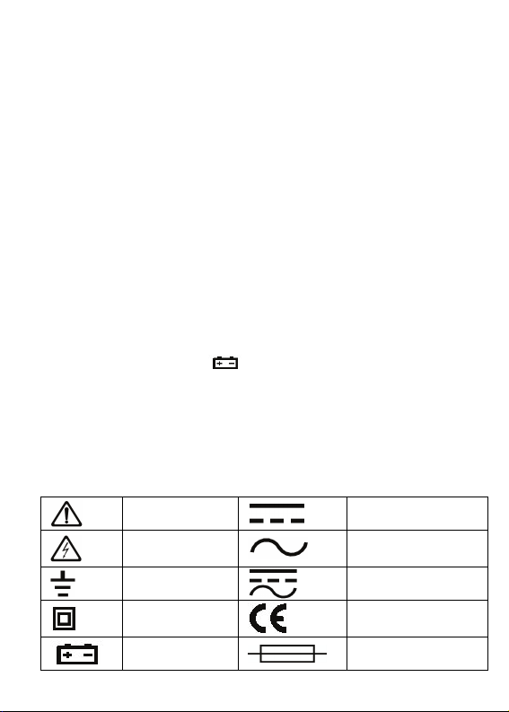
Front Panel Description
1. Instrument Model Number
2. LCD Display
3. RANGE: Auto Range/ Manual
Range switch, the default is set as
Auto Range mode when turning
on, press the button and switch to
Manual Range. At the Manual
Range mode, press the button
once, the range is switched to the
higher one, press the button again
to switch the range to the lowest
one when measuring the highest
range, the cycle is in proper order
from low to high. Keep pressing the button for 2 sec, return to
Auto Range mode. There is no Manual Range mode at
Frequency, hFE and Capacitance range.
4. HOLD: Date Hold button, press the button, the value is held on
LCD; Press the button again, exit the hold mode and get into the
normal measuring status. Press the button more than 2 seconds,
the back light will be light up, press again the backlight turns off
or automatically turns off after 10 seconds.
5. HZ/DUTY: Frequency/Duty Circle selection button, press the
button to switch between the Frequency and Duty Circle mode at
Frequency Range; Press the button to switch to Voltage or
Current/Frequency/Duty Circle model at AC Voltage or AC
Current Range.
6. MAX/MIN: Maximum, Minimum, press the button, the instrument
5
Page 7

gets into the MAX mode, the measuring maximum value will be
held at this mode; Press the button again to get into the MIN
mode, the measuring minimum value will be held at this mode. At
the MAX/MIN mode, the maximum or minimum value will be held
on LCD. Under this circumstance, there are no Bar Graph and
Auto Power Off function, hold pressing MAX/MIN button for 2
seconds, exit the MAX/MIN mode.
7. SELECT: function switch, press the button to switch the
measuring function.
8. RS232/REL: Relative Value Measurement, press the button to
the mode of Relative Value Measurement, press again to cancel
the Relative Value Measurement. Keep pressing the button more
than 2 seconds to switch to RS232 symbol appears on LCD, it
indicates the instrument is getting into the status of data
transmission. Keeping pressing the button more than 2 seconds,
RS232 symbol disappears, the data transmission is stopped.
9. Function/range selection knob: select the measuring function
and range.
10. 10A current input terminal: Measuring AC/DC 10A positive input
terminal, insert red test lead.
11. mA input terminal: Measuring AC/DC uA/mA and Temperature
positive input terminal. The hFE input terminal.
12. COM input terminal: Temperature negative input terminal,and
hFE input terminal, insert the black test lead.
13.
input terminal: measure Voltage, Frequency/Duty Circle,
Resistance, Capacitance, Diode and Continuity positive input
terminal, insert the red test lead
6
Page 8

Property
General Feature
1-1 Display: LCD
1-2 Max Display: 5999 (3 5/6) counts automatic polarity display and
unit display.
1-3 Measuring method: dual-integral A/D converter
1-4 Sampling rage: 3 times/second
1-5 Over range indication: display “OL”
1-6 Low battery indication: “
1-7 Operation environment: 0~40˚C relative humidity <80%
1-8 Storage environment: -10~50˚C relative humidity <80%
1-9 Power: 2pcs 1.5V batteries (AAA battery)
1-10 Dimension: 185mm x 92mm x 48mm
1-11 Weight: Approx. 390g (including batteries)
Technic Property
1. Accuracy: (a% × reading + digits) at 23 ± 5˚C , relative humidity
<75%.
2. One year calibration guarantee since the time dispatched from
the factory.
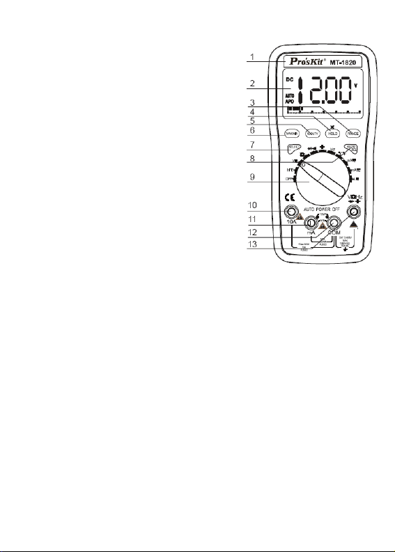
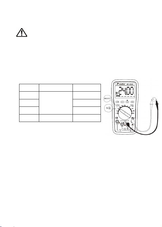
DC Voltage (DCV)
1. Turn the function/range selection knob to DCV/ACV. Insert the
red and black test lead separately to VΩHz and COM input terminal,
press “SELECT” button to switch to DCV measurement mode.
2. The instrument was preset as the Auto Range mode of DCV
measurement, display “AUTO” symbol on LCD, press “RANGE”
button to switch to the Manual Range mode.
3. Connect the test lead to the tested circuit in parallel, the polarity
of the red test lead and the tested voltage value will be displayed on
LCD simultaneously.
” appearance
7
Page 9
Note:
a) Do not measure the voltage higher than DC 1000V or AC 750V.
b) When measuring the high voltage, caution to avoid electric shock.
Cut the connection between the test lead and tested circuit at once
after measurement.
C) At the Manual Range mode, if “OL” is displayed on LCD, it
indicates the tested voltage value has exceeded the present range
limit, please select the higher range to complete the measurement
Range Accuracy Resolution
600mV 0.1mV
6V 1mV
60V 10mV
600V
1000V ±(1.0%+6d) 1V
Input impedance: >60MΩ at Range
600mV , 10MΩ at other range.
Overload protection: 1000V DC or 750V AC peak value.
±(0.5%+4d)
100mV
AC Voltage (ACV)
1. Turn the function/range selection knob to ACV/DCV, press
“SELECT” button to switch to ACV measurement mode. Insert the
red and black test lead separately to VΩHz and COM input terminal,
displayed as the following picture.
2. The instrument was preset as the Auto Range mode, displays
“AUTO” symbol on LCD, press “RANGE” button to switch to the
Manual Range mode. Press “Hz/DUTY” button to measure
Frequency/Duty Circle at the Auto Range or Manual Range mode.
But the frequency response is very low, at this time, it suits to
measure the circuit of high voltage and low frequency under the
circumstance of magnetic disturbance, such as
220V/50Hz-400Hz,380V/50Hz~400Hz.
3. Connect the test lead to the tested circuit in parallel,the polarity of
8
Page 10
the red test lead and the tested voltage value will be displayed on
LCD simultaneously
Note:
a) Do not measure the voltage higher than DC 1000V or AC 750V.
b) When measuring the high voltage, caution to avoid electric shock.
Cut the connection between the test lead and tested circuit at once
after measurement.
C) At the Manual Range mode, if “OL” is displayed on LCD, it
indicates the tested voltage value has exceeded the present range
limit, please select the higher range to complete the measurement
Range Accuracy Resolution
6V 1mV
60V 10mV
600V
750V ±(1.0%+10d) 1V
Input impedance: 10MΩ. Overload
protection : 1000V DC or 750V AC peak
value.
Frequency response: 40-400Hz. Indication: average value
response (RMS of sine wave).
Duty Circle indication (0.1%~99.9%)
±(0.8%+10d)
100mV
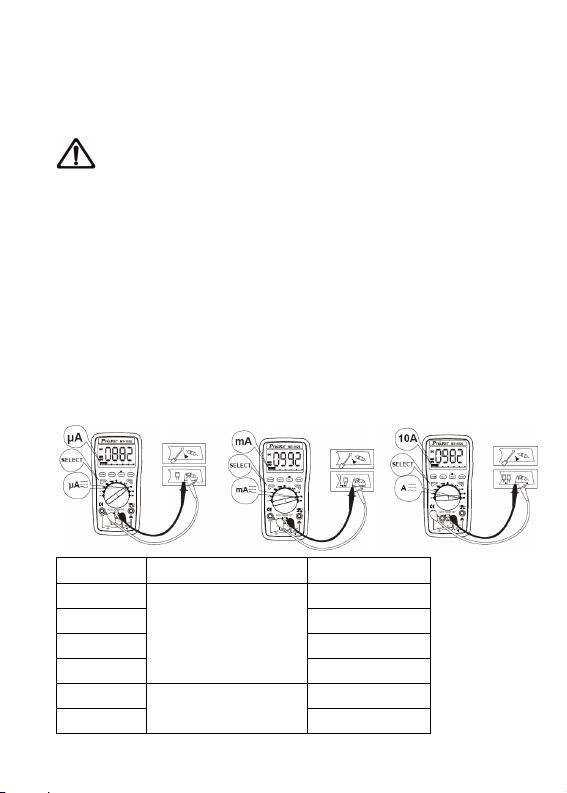
DC Current (DCA)
1. Insert the black test lead to “COM” input terminal and the red test
lead to “mA ”or “10A”, displayed as the picture.
2. Turn the function/range selection knob to current range, press
“SELECT”, switch to DC measurement mode, then connect the test
lead with the tested circuit in series, the polarity of the red test lead
and the tested current value will be displayed on LCD
simultaneously.
9
Page 11
3. At the Manual Range mode,if “OL” is displayed on LCD, it
indicates the test current value has
exceeded the present range limit, please select the higher range
to complete the measurement.
Note:
a) Do not measure the current higher than 10A at Range 10A and
higher than 6000uA at uA Range and higher than 600mA at mA
Range, otherwise the fuse will be burnt out or the instrument will be
damaged.
b) Do not connect the test lead to any circuit in parallel when the
test lead is inserted in the current input terminal, otherwise it is
possible to damage the instrument or endanger the safety of the
users. Cut the connection between the test lead and tested circuit at
once after measurement.
Range Accuracy Resolution
600uA 0.1μA
6000uA 1μA
60mA 10μA
600mA
6A 1mA
10A
±(1.0%+10d)
±(1.2%+10d)
100μA
10mA
10
Page 12

Max input current: 10A (less than 15 seconds).
Overload protection: 0.5A/250V fuse, 10A/250V fuse.
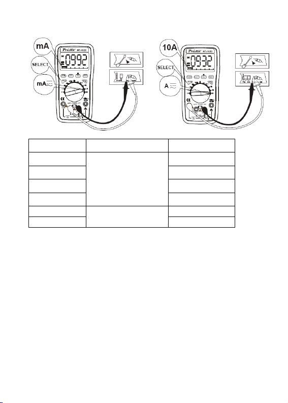
AC Current (ACA)
1. Insert the black test lead to “COM” input terminal and the red test
lead to “mA ”or “10A”input terminal,displayed as the picture.
2. Turn the function/range selection knob to current range, press
“SELECT”, switch to AC measurement mode, then connect the test
lead to the tested circuit in series, the polarity of
the red test lead and the tested current value will be displayed on
LCD simultaneously
3. At the Manual Range mode,if “OL” is displayed on LCD, it
indicates the tested current value has exceeded the present range
limit, please select the higher range to complete the measurement.
Note:
a) Do not measure the current higher than 10A at Range 10A and
higher than 6000uA at uA Range and higher than 600mA at mA
Range, otherwise the fuse will be burnt out or the instrument will be
damaged.
b) Do not connect the test lead to any circuit in parallel when the
test lead is inserted in the current input terminal, otherwise it is
possible to damage the instrument or endanger the safety of the
users. Cut the connection between the test lead and tested circuit at
once after measurement.
11
Page 13
Range Accuracy Resolution
600uA 0.1μA
6000uA 1μA
60mA 10μA
600mA
6A 1mA
10A
Max input current : 10A (less than 15 seconds). Frequency
response: 40-100Hz
Overload protection:0.5A/250V fuse, 10A/250V fuse. Duty Circle
Indication: (0.1%-99.9%)
±(1.5%+10d)
±(2.0%+15d)
100μA
10mA
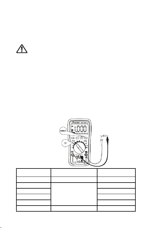
Resistance (Ω)
1. Turn the function/range selection knob to Ω, insert the red and
black test lead separately to VΩHz and COM input terminal.
2. Connect the test lead to the tested resistance in parallel, the
tested resistance value will be displayed on LCD
3. Auto Range mode is preset when turning on, press “RANGE”
button to switch to Manual Range mode.
12
Page 14
4. At the Manual Range mode,if “OL” is displayed on LCD, it
indicates the tested resistance
value has exceeded the present range limit, please select the
higher range to complete the measurement.
Note:
a) When measuring the in-circuit resistance, Make sure all the
power of the tested circuit has been turned off and all capacitors are
fully discharged.
b) It will cause the reading incorrect to input any voltage when
measuring the resistance. If the voltage exceeds 250V, over-range
protection voltage, it is possible to damage the instrument and
endanger the safety of the users.
c) At Range 600Ω, short-circuit the test lead to measure the wire
resistance, and then subtract it from the real measurement.
Range Accuracy Resolution
600Ω ±(0.8%+5d) 0.1Ω
6KΩ 1Ω
60KΩ 10Ω
600KΩ 100Ω
6MΩ
60MΩ ±(1.2%+10d) 10KΩ
±(0.8%+4d)
1KΩ
13
Page 15

Open circuit voltage: 400mV. Over range protection: 250V AC/DC
peak value.
Diode and Continuity Test
1. Turn the function/range selection knob to Range, Insert the
red and black test lead separately to VΩHz and COM input terminal.
Press “SELECT” button to choose the Buzzer or Diode
measurement function.
2. Connect the red test lead to the positive pole of the tested diode,
BLACK test lead to the negative pole.
4. Read the present test result from LCD. (Note: no Bar Graph
display at Diode Range)
Note:
a) If the diode is open circuit or the polarity is connected counter,
“OL” will be displayed on LCD.
b) When measuring the in-circuit diode, make sure all the power of
the tested circuit has been turned off and all capacitors are fully
discharged.
c) Cut the connection between the test lead and tested circuit at
once after measurement.
14
Page 16

Range Display Test Condition
Diode
Overload protection: 250V DC/AC peak value.
Forward
voltage drop
Buzzer sound
at less than
50Ω
Warning: Do not input the voltage at the range for safety.
Forward AC Current:1.0mA,
Counter Voltage: 3.0V
Open Voltage: 0.5V
Capacitance (C)
1.Turn the function/range selection knob to Capacitance Range.
Insert the red and black test lead separately to VΩHz and COM
input terminal.
2. Connect the test lead to the tested capacitor in parallel, the
tested capacitor value will be displayed on LCD.
3. If “OL” is displayed on LCD, it indicates the test capacitor value
has exceeded the present range limit.
Note:
a) When measuring the in-circuit capacitor, make sure all the power
of the tested circuit has been turned off and all capacitors are fully
discharged.(Note: no Bar Graph display at this range)
b) It requires longer testing time when measuring the large
capacitor, it takes about 15 seconds at Range 100uF.
c) Cut the connection between the test lead and tested circuit at
15
Page 17

once after measurement.
Range Accuracy Resolution
40nF ±(5.0%+30d) 10pF
400nF 100pF
4μF 1nF
40μF
200μF ±(5.0%+10d) 100nF
Overload protection: 250V DC/AC peak value
±(3.5%+8d)
10nF
WARNING: Do not input any voltage at this range for safety!
Frequency (Hz)
1. Turn the function/range selection knob to Hz Range. Insert the
red and black test lead separately to VΩHz and COM input
terminal.
2. Connect the test lead to the tested signal source in parallel, Read
the present test result from LCD. (Note: no Bar Graph display at this
range)
16
Page 18

3. When measuring Frequency, press “Hz/DUTY” button once to
get into the mode of DUTY measurement, and press “Hz/DUTY”
button again to return to the mode of Frequency measurement.
4. When measuring AC current or voltage, press “Hz/DUTY” button
to get into the mode of Frequency measurement, and press
“Hz/DUTY” button again to get into the mode of Duty Circle
measurement, and press the button third to return to the mode of
AC current or voltage measurement.
Note:
a) Do not input the signal
more than 60V. Otherwise it is
possible to damage the
instrument and endanger the
safety of the users.
b) Cut the connection
between the test lead and
tested circuit at once after
measurement.
Range Accuracy Resolution
100Hz 0.01Hz
1000Hz 1Hz
10kHz 10Hz
100kHz 100Hz
1MHz 1kHz
30MHz
Input sensitivity: 1.0V.
Overload protection: 250V DC/AC peak value.
Duty Circle Indication: (0.1%-99.9%)
±(0.5%+4d)
10kHz
17
Page 19

Transistor Test
1. Turn the function/range selection knob to “hFE” Range,
displayed as the right picture.
2. Insert the accessory of
Transistor test into the “mA ”
and “COM” input terminal,
displayed as the
picture.According to the model of
the tested transistor, insert the
accessory accordingly into the
terminal of “EBC” of “NPN” or
“PNP”.
4. Read the present test result
from LCD.
Note:
a) Do not input the current or voltage at the input terminal of “mA ”,
“COM” or transistor accessory, otherwise it is possible to damage
the instrument or endanger the safety of the users.
b) There are no Data Hold, MAX/MIN, Bar Graph function at
Transistor Test mode
Range Scope of Display Test Condition
hFE(NPN or
PNP)
0-1000
Temperature Test
1. Turn the function/range selection knob to Temperature Range.
2. Insert the two ends of the temperature sensor Into the “COM”
and “mA” input terminal, the
Base Current:1mA
VCE:2.1V
18
Page 20

positive end into the “mA” input terminal.
3. Connect the sensor of the temperature cable to the surface or
inside of the tested object,
read the present test result from LCD.
4. Press “SELECT” button to switch Fahrenheit or Centigrade
temperature measurement mode.
Note:
a) Without the signal input, LCD automatically displays the present
temperature.
b) Do not replace the temperature sensor at will. Otherwise the
accuracy can’t be assured.
c) Do not input the voltage at Temperature Range, caution to avoid
damaging the instrument.
Range Accuracy Resolution
-20℃ - 400℃ ±(1.0%+50d) 0.1℃
400℃ - 1000℃ ±(1.5%+15d) 1℃
0℉ - 750℉ ±(1.0%+50d) 0.1℉
750℉ - 1832℉ ±(1.5%+5d) 1℉
Overload protection: 0.5A/250V
19
Page 21

Other Functions and Instrument Maintenance
• Other Functions
1. Data Hold
Press “HOLD” button, the present value is held on LCD; Press the
button again, exit the hold mode and get in the normal measuring
status.
2. Auto Power Off
Stop working for 15 minutes, the instrument will auto power off, and
get into the sleeping mode. The buzzer inside will sound 5 times
within one minute before powering off, there is a long sound one
minute later and the instrument gets into the sleeping mode. Press
any key to restart the power.
3. Ress “REL/RS232”button to get into the Relative Value
Measurement mode, Keep holding “REL/RS232” button more than
2 seconds, RS232 symbol is displayed on LCD, it indicates it is the
status of the instrument connecting with PC, then connect the
instrument to PC by USB Cable, accessory of the instrument, and
then can transmit the measuring data to PC, it is convenient to
record, analyze, process and print the measuring results, etc.
Please refer the details to the description in the software.
4. Backlight function: if need to measured in the dark environment,
please press the "HOLD" button more than 2 seconds, then the
LCD can be light for help reading, about 10 seconds the light turn
off. If need to lighting again, press "HOLD" button for 2 seconds
again.
20
Page 22

Instrument Maintenance
This is a highly precise instrument, do not try to modify the inner
circuit at will.
1. Keep the instrument dry, and keep it away form dust and shock.
2. Do not store and use the instrument in high humility, high
temperature, combustible, explosive and strong magnetic places.
3. Clean the surface of the instrument with the damp cloth and
gentle detergent, do not use the strong solvent like the abrasive
cleaner and alcohol, etc.
4. Take out the batteries if do not use the instrument for a long time
to prevent the batteries from leaking the liquid to corrode the
instrument.
5. When LCD displays “
batteries as the following steps:
5-1. Loose the screw that fixes the batteries, and remove the
battery case.
5-2. Remove the spent 1.5V batteries, and replace them by two
same type new batteries. It is better to use alkaline batteries for
lengthening the usage time.
5-3. Fit on the battery case and tighten the screw.
5-4. The steps of replacing the fuse are same as the above. When
replacing the fuse, please use the same specification, same type of
fuse.
“ symbol, should replace the
Note:
1. Do not input the voltage more than 1000V DC/AC peak value.
2. Do not measure the voltage at the Current, Resistance, Diode
and Buzzer Range.
3. Do not use this instrument to measure before fixing the battery or
21
Page 23

tightening the bottom case
4. Please remove the test lead from the tested point and turn the
power off before replacing the battery or fuse.
FAULT ELIMINATION
If the instrument does not work properly, the below methods can
help you to solve the problems quickly. If the fault still can’t be
eliminated, please contact the maintenance center or the
distributors:
Fault Solution
Power off – turn on the power
No display
Hold Key- set a correct mode
Replace battery
symbol appearance
No current input
Error value
The instruction manual is subject to change without notice.
The contents in the instruction manual are considered to be correct, if the users find any
errors or pretermission, etc., please contact the manufacturer.
The manufacturer hereby will not be responsible for any accident and damage caused by
the improper operation.
The functions described in this instruction manual do not be the reason for special usage.
Replace battery
Replace fuse
Replace battery
22
Page 24

MT-1820
3 5/6 USB 連線型雙顯自動錶
目 錄
概述 ……………………………………………………………..24
開箱檢查 …………………………………………………………… 24
安全注意事項…………………………………………………24
安全符號說明 …………………………………………………26
儀錶面板及按鍵功能說明 ………………………………………… 26
其他功能…………………………………………………28
特性…………………………………………………….. 28
直流電壓(DCV) ………………………………………………… 29
交流電壓(ACV) ………………………………………………… 30
直流電流(DCA) ………………………………………………… 31
交流電流(ACA) …………………………………………………32
電阻…………………………………………………………………. 34
二極體及通斷測試 ………………………………………………… 35
電容(C) ……………………………………………………………..36
頻率(Hz) ……………………………………………………………..38
電晶體測量及溫度測量………………………………………… 39
溫度測量………………………………..……………………..40
通訊連接……………………………………………………………..41
儀錶保養…………………………………………………………….. 42
故障排除………………………………………………………….. 42
23
Page 25

一.概述
MT-1820 一種性能穩定、高可靠性 3 5/6 USB 連線型雙顯自動錶,儀
錶採用 24mm 字高 LCD 顯示器,讀數清晰,顯示直觀,操作方便,
可用來測量直流電壓、交流電壓、直流電流、交流電流、電阻、電容、
頻率、占空比、電晶體、二極體及通斷測試;同時還設計有 61 段類
比棒條顯示、單位符號顯示、資料保持、相對值測量(REL),帶USB
電腦介面,自動/手動量程轉換、自動斷電及報警功能。整機採用直接
驅動 LCD 的 4 位元微處理器和雙積分 A/D 轉換積體電路,提供高分
辨力、高精度的數位顯示驅動,該表功能齊全,測量準確度高,使用
方便,是實驗室、工廠、無線電愛好者及家庭的理想工具。
二、開箱檢查
打開包裝箱取出儀錶,仔細檢查以下附件是否缺少或損壞,如有缺少
或損壞請立即與經銷商聯繫。
•數字多用表 一台
•使用說明書 一本
•表棒 一副
•溫度測試線(K 型熱電偶) 一條
•USB 連接線 一條
•軟體光碟 一張
•電晶體測試座 一個
三、安全注意事項
MT-1820 符合IEC1010 條款(國際電工委員會頒佈的安全標準)。使
用污染等級 2 的安全要求進行設計和生產。
警 告:
24
Page 26

為避免危險及使用者的安全,在使用儀錶之前請仔細閱讀本使用手
冊,並嚴格遵守安全警告資訊和操作說明來使用本儀錶。
在測量 30V 以上電壓,測量 10mA 以上電流,測量帶電感負載的交
流電力線,測量電力波動期間的交流電力線時,謹防電擊。
2.測量前,檢查功能/量程選擇開關是否置於正確的檔位,要檢查表棒
是否可靠接觸,是否正確連接、是否絕緣良好等,以避免電擊。
3.儀錶只有和所配備的表棒一起使用才符合安全標準要求。如表棒線
破損時,必需更換上同樣型號或者相同電氣規格的表棒線。
4.不要使用其他未經確認或未認可的保險管來更換儀錶內部的保險
管,只能換上同樣型號或相同規格的保險管,更換前表棒必需離開被
測量點,確保輸入端無任何信號。
5.不要使用其他未經確認或未認可的電池來更換儀錶內的電池,只能
換上同型號或相同電氣規格的電池,更換前表棒必需離開被測量點,
確保輸入端無任何信號。
6.在進行電氣測量時,身體切勿直接接觸大地,不要接觸可能存在地
電勢裸露的金屬端子、輸出口、引線夾等。通常使用的乾燥的衣服、
膠鞋、膠墊以及其他絕緣材料,保持你的身體與大地絕緣。
7.不要在高溫、高濕、易燃、易爆和強磁場環境中存放及使用。
8.測量超過儀錶所允許的極限電壓值有可能損壞儀錶和危及操作人
員的安全。在儀錶面板上標有儀錶所允許測量的極限電壓值,切勿測
量超過此標準的安全,請勿輸入超過規定的極限值,以防電擊和損壞
儀錶。
9.當表棒線插入電流插座時切勿測量任何電壓以免損壞儀錶和危及
操作人員的安全。
10.不要嘗試校準或維修儀錶。有需要時必須有專門培訓或認可的有
資格專業人員才能進行。
11. 在測量時功能/量程選擇開關必需置於正確的量程檔位,在轉換功
能/量程選擇開關時,請一定要先將表棒線與被測物件斷開,確保輸
入端沒任何信號輸入。嚴禁在測量進行中轉換功能/量程選擇開關。
25
Page 27

12.當 LCD 顯示“
13.不允許表棒插在電流端子去測量電壓!
14.請不要隨意改變儀錶線路,以免損壞儀錶和危及安全。
”時,請及時更換電池以確保測量精度。
四、安全符號說明
警告!
高壓!危險!
大地
雙重絕緣
電池欠壓
直流
交流
交直流
符合歐洲工會指令
保險絲
五、儀錶面板及按鍵功能說明
1. 儀錶型號
2. 61 段類比棒條 LCD 屏顯示。
3. RANGE:自動/手動量程切換,開機時預設為自動量程,按一下
切換為手動量程,在手動量程模式下,每按一下往上跳一檔,到
最高檔時再按此鍵又跳到最低檔,依次循環。如按此鍵超過 2
秒則切換回到自動量程。頻率、fHE 及電容檔沒有手動量程功能。
4. HOLD : 讀數保持,按此鍵顯示值被鎖定,再按此鍵解除鎖定狀
態。
26
Page 28

5. Hz/DUTY: 頻率/占空比選擇鍵,
在頻率檔按此鍵可以切換頻率或
占空比功能;在交流電壓或交流電
流檔位時,按此鍵可以在電壓或電
流/頻率/占空比之間作切換。
6. MAX/MIN : 最大值/最小值顯示,
按下此功能鍵,進入 MAX 模式保
持測量的最大值:再按一次進入
MIN 模式保持測量的最小值,在此
工作環境下無類比棒條顯示和自
動關機功能,按 MAX/MIN 鍵 2 秒
後,退出 MAX 或 MIN 測量測試。
7. SELECT : 按鍵開關,用於選擇各
種測量功能切換。
8. RS232/REL:相對值測量,按一
下此鍵為相對值測量,再按一次取消相對值測量,以此循環,如
按此鍵超過2 秒則切換到資料傳輸PC 模式,LCD 屏上有RS232
顯示,此時電錶資料可輸出至 PC,如再按此鍵超過2 秒則RS232
在 LCD 屏上消失,此時關閉 RS232 資料輸出。
9. 功能/量程選擇開關 : 用於選擇各種測量功能和量程。
10. 10A 電流輸入插孔:測量交直流電流 10A 檔的正輸入端,插入
紅表棒。
11. mA 輸入孔:測量交直流微安、毫安培和溫度檔的正輸入端,以
及 hFE 測量端。
12. COM 輸入孔:負輸入端,溫度檔的負輸入端, 以及 hFE 測量端,
插入黑表棒。
13.
輸入插孔:測量電壓、頻率/占空比、電阻、電容、二極
體以及通斷測試的正輸入端,插入紅表棒 。
27
Page 29

六、其他功能
1.自動斷電
當儀錶停止使用 15 分鐘後,儀錶便自動斷電(關機),然後進入睡眠
(關機)狀態,斷電前一分鐘內置蜂鳴器會發出 5 聲提示,一分鐘後
長響一聲進入休眠(關機)狀態,若要重新啟動電源(開機),請按
任意鍵或撥動功能/量程選擇開關,均可重新開機。
2. 按“RS232/REL”鍵,為相對值測量,常按“RS232/REL”鍵,大於兩
秒,顯示幕上有 RS232 顯示,此時儀錶可與電腦連接,利用所附的
USB 連接線連接儀錶及電腦,可將所測量的資料進行記錄、分析、
處理和列印。詳細請參考軟體中的說明。
3. 背光照明功能: 若需要在昏暗環境下進行測量,請按下”HOLD”鍵
2 秒, 背光照明開啟,持續大約 10 秒後關閉. 若需要繼續照明,再次
按〞HOLD〞鍵 2 秒,開啟照明。
七、特性
一般特性
• 顯示方式:液晶顯示
• 最大顯示:5999、3 5/6 位元自動極性顯示和單位顯示
• 測量方式:雙積分式 A/D 轉換
• 採樣速率:約每秒 3 次
• 過量程顯示:顯示“OL”
•低電壓顯示:“
•工作環境:0~40℃,相對濕度<80%
•儲存環境:-10~50℃,相對濕度<80%
•電 源:兩節 1.5V 電池(“AAA”電池)
•體積(尺寸):185mm x 92mm x 48mm(長×寬×高)
•重 量:約 390g(包括電池)
”符號出現
28
Page 30

技術特性
•準確度:±(讀數的% + d 位數),保證準確度環境溫度 23±5℃,相
對濕度<75%,
•校準保證期從出廠日起為一年。
八、直流電壓(DCV)
1. 將功能/量程開關旋至交/直流電壓,紅黑表棒分別插入“VΩHz”和
“COM”孔中。
2. 儀錶的起始狀態為自動量程直流電壓模式,LCD 顯示“AUTO”符
號,按” RANGE“鍵,可轉換為手動量程模式。
3. 將表棒接觸測試點並聯到被測電路上,紅色表棒線的極性和被測
電壓值將同時顯示在 LCD 營幕上。
注 意:
a) 不能測量高於 DC1000V 或 AC750V 的電壓。
b) 在測量高壓時,特別注意避免觸電。在測試完後立即斷開表棒與
被測電路。
c) 手動量程模式下,如營幕上顯示“OL”,則被測電路已經超過所選
量程,請選擇更高的量程檔位來完成此次測量。
量 程 準確度 分辨率
600mV 0.1mV
6V 1mV
60V 10mV
600V
1000V ±(1.0%+6d) 1V
±(0.5%+4d)
100mV
29
Page 31

輸入阻抗:600mV 量程>60MΩ,其餘為 10MΩ。
超載保護:1000V 直流或 750V 交流峰值。
九、交流電壓(ACV)
1.將功能/量程開關旋至交/直流電壓,按”SELECT”選擇交流電壓,將
紅黑表棒分別插入“VΩHz”和“COM”。
2.儀錶的起始狀態為直流電壓模式,按”SELECT”鍵可切換為交流電
壓模式,LCD 初始為自動量程顯示“AUTO”符號,按“RANGE“鍵,可
轉換為手動量程模式。
按下“Hz/DUTY”鍵可測量頻率/占空比測量,但此時頻率回應較低,適
用於磁場干擾環境下的高壓低頻測量,如 220V/50Hz-400Hz,
380V/50Hz~400Hz。
3.將表棒接觸測試點並聯到被測電路上,紅色表棒線的極性和被測電
壓值將同時顯示在營幕上。
注 意:
a) 不能測量高於 DC1000V 或
AC750V 的電壓。
b) 在測量高壓時,要特別注意避免
觸電,並在測試完後表棒與被測電路
立即斷開。
c) 手動量程模式下,如營幕上顯示
“OL”,則被測電路已經超過所選量
程,請選擇更高的量程檔位來完成此
次測量。
30
Page 32

量 程 準確度 分辨率
6V 1mV
60V 10mV
600V
750V ±(1.0%+10d) 1V
輸入阻抗: 10MΩ。超載保護:1000V 直流或 750V 交流峰值。
頻率回應: 40~400Hz,顯示: 平均值回應(以正弦波有效值校準)。
占空比顯示:(0.1%-99.9%)。
±(0.8%+10d)
100mV
十、直流電流(DCA)
1.將黑表棒插入“COM”孔中,紅表棒插入“mA ”或“10A”孔中,如下圖
所示。
2.將功能/量程開關轉至所需電流檔,LCD 顯示“AUTO”符號,初始值
均設定為直流測量方式,
按“RANGE“鍵,可轉換為手動量程模式。
3.將表棒接觸測試點串聯到被測電路上,被測電流值及紅表棒點的電
流極性將同時顯示在螢幕上。
4.手動量程模式下,如螢幕上顯示“OL”,表示被測量電流已超過所
選,請選擇更高的量程來測量。
注 意:
a)在 10A 檔不能測量大於 10A 的電流,“uA”檔不能測量大於6000uA
的電流,“mA”檔不能測量大於 600mA 的電流,否則會將保險絲燒斷
或損壞儀錶。
b)當表棒插在電流輸入端時,嚴禁將表筆並聯在任何電路上,否則有
可能損壞儀錶和危及使用者安全,在完成所有得測量後,要立即斷開
表棒與被測電路。
31
Page 33

量 程 準確度 分辨率
60OuA 0.1μA
60O0uA 1μA
60mA 10μA
600mA
6A 1mA
10A
最大輸入電流:10A(不超過 15 秒)
超載保護:0.5A/250V 保險絲;10A/250V 保險絲。
±(1.0%+10d)
±(1.2%+10d)
100μA
10mA
十一、交流電流(ACA)
1.將黑表棒插入“COM”孔中,紅表筆插入“mA ”或“10A”孔中,如右圖
所示。
2.將功能/量程開關轉至所需電流檔,按“SELECT”鍵,選擇交流測量
方式,將表棒接觸測試點串聯到被測電路上,被測電流值及紅表筆點
的電流極性將同時顯示在螢幕上 。
3.在手動量測模式下,如果顯示幕上顯示“OL”,表示被測量電流已超
過當前量程,請選擇更高的量程來測量。
32
Page 34

注 意:
a) 在10A 檔不能測量大於 10A 的電流,“uA”檔不能測量大於6000uA
的電流,“mA”檔不能測量大於 600mA 的電流。
b)當表棒插在電流輸入端時,嚴禁將表棒並聯在任何電路上,否則有
可能損壞儀錶和危及使用者安全,在完成所有得測量後,要立即斷開
表棒與被測電路。
量 程 準確度 分辨率
600uA 0.1μA
6000uA 1μA
60mA 10μA
600mA
6A 1mA
10A
最大輸入電流:10A(不超過 15 秒)。
超載保護:0.5A/250V 保險絲;10A/250V 保險絲。
頻率回應: 40~100Hz。
占空比顯示:(0.1%~99.9%)
±(1.5%+10d
±(2.0%+15d)
100μA
10mA
33
Page 35

十二、電阻(Ω)
1.將功能/量程開關旋至“Ω”檔,將紅黑表棒分別放入“VΩHz”和
“COM”。
2.將表棒的測試端並聯到被測量電阻上,被測電阻值會顯示在營幕
上。
3.開機預設為自動量程,LCD 顯示“AUTO”符號,按“RANGE”鍵選擇
手動量程模式。
4.在手動量程模式下,如果營幕上顯示“OL”表明已經超過當前量程,
請選擇更高的的量程來完成。
注 意:
a) 測電阻時,必須先將被測電路內所有的電源關斷,並將所有的電
容充分放電。
b) 在測量電阻時,任何電壓的出現都會引起測量讀數不準,如果超
過 250V 保護電壓,則有可能損壞和危及使用者的安全。
c) 在使用600Ω 量程時,應先將表棒短路測得引線電阻,然後在實測
中減去引線電阻值。
34
Page 36

量 程 準確度 分辨率
600Ω ±(0.8%+5d) 0.1Ω
6kΩ 1Ω
60kΩ 10Ω
600kΩ 100Ω
6MΩ
60MΩ ±(1.2%+10d) 10kΩ
開路電壓:400mV。
超載保護:250V 直流或交流峰值。
±(0.8%+4d)
1kΩ
十三、二極體及通斷測試
將功能/量程選擇開關旋到“ ”檔。
2. 將紅、黑色表棒分別插入“VΩHz”和“COM”輸入端,再按“SELECT”
選擇二極體或通斷測量。
3.將紅色表棒接到二極體的正極,黑色表筆接到二極體的負極。
4.從營幕上讀出結果。(注:二極體檔無類比棒條顯示)。
注 意:
a) 如果二極體開路或極性接反時,顯示幕上將顯示“OL”。
b) 檢查二極體時,必須先將被測線路內所有的電源斷開,並將所有
的電容充分放電。
c) 在完成測量之後,要立即斷開表筆與被測電路的連接。
35
Page 37

量 程
超載保護:250V 直流或交流峰值。
顯 示 值 測 試 條 件
正向直流電流約
二極體正向壓降
峰鳴器發聲長響,測試二點
電阻約 50Ω
警 告:為了安全在此量程禁止輸入電壓值!
1.0mA ,反向電壓約
3.0V
開路電壓約 0.5V
十四、電容(C)
1.將功能開/量程開關旋到電容檔。將紅黑表棒分別插入“VΩHz”和
“COM”輸入端。
2.將表棒的測試端並聯到被測電容上,被測電容值將顯示在營幕上。
3.如果營幕上顯示“OL”,則表示被測電容值已超過當前量程。
36
Page 38

注 意:
a) 在測電容時,必須先將被測線路內所有的電源斷開,並將所有的
電容充分放電。注意:該檔無類比棒條顯示)
b) 當測量大電容時,需要較長的時間,在 100uF 時約 15 秒。
C) 完成所有的測量後,要立即斷開表棒與被測電路的連接。
量 程 準確度 分辨率
40nF ±(5.0%+30d) 10pF
400nF 100pF
4μF 1nF
40μF
200μF ±(5.0%+10d) 100nF
超載保護:250V 直流或交流峰值。
警 告:為了安全在此量程禁止輸入電壓值!
±(3.5%+8d)
37
10nF
Page 39

十五、頻率(Hz)
1. 將功能/量程開關旋到“Hz”檔。
將紅黑表棒分別插入“VΩHz”和
“COM”輸入端。
2. 將表棒的測試端並聯到待測信
號源上,從營幕上讀出結果(注
意:該檔無類比棒條顯示)。
3. 在進行頻率測量時,按一次
“Hz/DUTY”鍵進入占空比測量狀
態,再按一 次 “Hz/DUTY”鍵進入頻
率測量狀態。
4. 當功能/量程開關旋到交流電流/交流電壓檔測量時,按“Hz/DUTY”
鍵進入頻率測量狀態,再按一次“Hz/DUTY”鍵進入占空比測量狀態,
第三次按“Hz/DUTY”鍵返回到原測量狀態。
注 意:
不要輸入高於 60V 的信號,否則可能損壞儀錶並危及人身
a)
安全。
b) 在完成所有的測量後,要立即斷開表棒與被測電路
量 程 準確度 分辨率
100Hz 0.01Hz
1000Hz 1Hz
10kHz 10Hz
100kHz 100Hz
1MHz 1kHz
30MHz
±(0.5%+4d)
10kHz
38
。
Page 40

輸入靈敏度:1.0V。
超載保護:250V 直流或交流峰值。
占空比顯示:(0.1%~99.9%)。
十六、電晶體測量
1. 將功能/量程開關旋到“hFE”檔如右圖。
2. 將電晶體附件如圖插入“mA ”與“COM”孔中。
3. 根據被測電晶體的型號,插入電晶體附件所對應的:“NPN”或
“PNP”的“E B C ”孔中。
4. 從營幕上讀出結果。
注 意:
a) 嚴禁在“mA ”與“COM”及電晶體附件孔輸入電流或電壓,否則有可
能損壞儀錶和危及使用者安全。
b) 在電晶體測試功能下無讀數保持、最大值、最小值、類比棒條顯
示功能。
39
Page 41

量 程 顯 示 範 圍 測 試 條 件
hFE(NPN 或 PNP) 0-1000
基極電流約 1mA VCE
約 2.1V
十七、溫度測量
1.將功能/量程選擇開關旋到溫度檔。
2.將溫度探頭的輸入端插入“COM”,正端插入“mA”中,將溫度探頭的
感應端置於被測物件的表面上,如下圖的水中。
3.從營幕上讀出測量結果,按“SELECT”選擇華氏度,再按“SELECT”
可選擇攝氏度。
注 意:
a)當輸入端開路時,顯示常溫。
b)請勿隨意更換溫度測試線,否則將不能保證測量的準確度。
c)嚴禁在溫度檔輸入電壓,否則有損壞儀錶的危險!
40
Page 42

量程 準確度 分辨率
-20℃-400℃ ±(1.0%+50d) 0.1℃
400℃-1000℃ ±(1.5%+15d) 1℃
0℉-750℉ ±(1.0%+50d) 0.1℉
750℉-1832℉ ±(1.5%+5d) 1℉
K 型熱電偶(鎳鉻-鎳硅)香蕉探頭。
警 告:為了安全在此量程禁止輸入電壓值!
十八、通訊連接
1.按包裝所提供的光碟對應儀錶的型號,選擇 setup 的文件安裝。
2.將儀錶通過 USB 連接線與電腦連接好。
3.長按“RS232/REL”兩秒以上,螢幕上出現 RS232 顯示。
4.測量的資料傳輸到電腦,此時可以對資料進行記錄、分析、處理和
列印等。
詳細請參考軟體中的說明。
十九、儀錶保養
該儀錶是一台精密儀器,使用者不要隨意更改電路。
1.請遠離有水氣及灰塵之處。請勿重摔。
2.請勿在高溫高濕、易燃易爆和強磁場的環境下存放、使用儀錶。
3.請使用濕布和溫和的清潔劑清潔儀錶外表,勿使用研磨劑及酒精等
烈性溶劑。
4.如果長時間不使用,應取出電池,防止電池漏液腐蝕儀錶。
5.請注意電池使用情況,當 LCD 顯示出“
電池。
”符號閃爍時,應更換
41
Page 43

步驟如下:
a.取出後蓋上固定電池的螺絲,取下電池蓋。
b.取下 2 個 1.5V 電池,換上兩個新的電池,雖然任何標準 1.5V 電池
都可使用,但為加長使用時間,最好使用鹼性電池;
c.裝上電池蓋,鎖緊螺絲。
d.保險絲更換:步驟同上。更換保險絲時,請使用規格、型號相同的
保險絲。
二十、故障排除
如果您的儀錶不能正常工作,下面的方法可以幫助您快速解決一般問
題。如故障仍無法排除,請與維修中心或經銷商聯繫。
故障現象
沒顯示
符號出現
電流沒輸入
顯示誤差大
注 意:
1.不要將高於 1000V 直流或交流峰值電壓接入。
2.不要在電流檔、電阻檔、二極體檔和蜂鳴器檔測量電壓值。
3.在電池沒有裝好或後蓋沒有上緊時,請不要使用此表。
4.在更換電池或保險絲前,請將測試表筆從測試點移開,並關機。
本說明書如有改變,恕不另行通知。
本說明書的內容被認為是正確的,若用戶發現有錯誤、遺漏等,請與生產廠家聯繫。
本公司不承擔由於用戶錯誤操作所引起的事故和危害。
本說明書所講述的功能,不作為將產品用做特殊用途的理由。
檢查部位及方法
電源未接通
保持開關
換電池
換電池
換保險絲
換電池
42
Page 44

43
 Loading...