

Page 1
MT-1505
Automatic Pocket Meter
User’s Manual
st
1
Edition, 2012
©2012 Copyright by Prokit’s Industries Co., Ltd.
Page 2
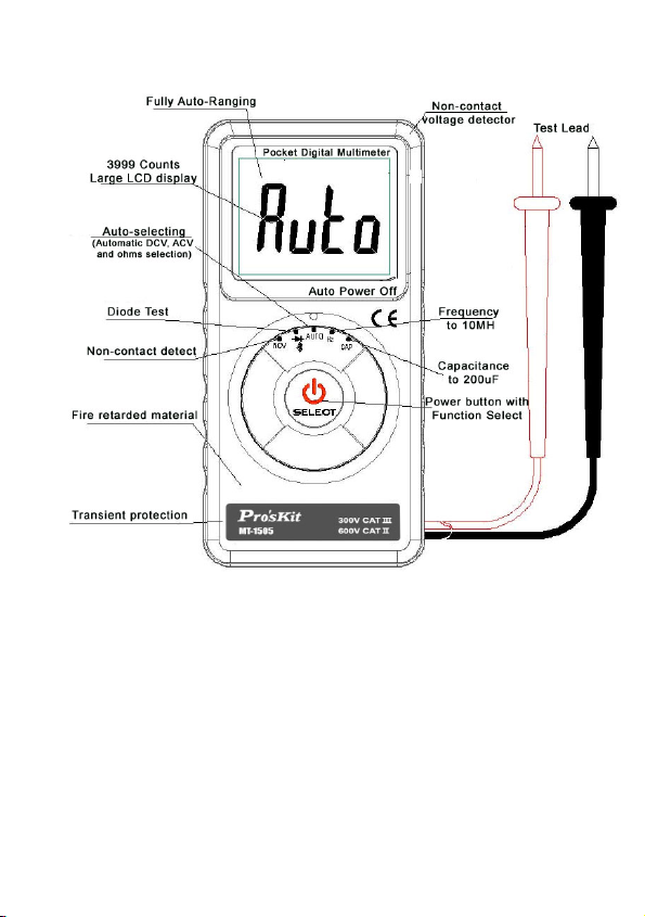
Front panel description
Introduction
This unique meter has a full complement of features in a
compact package only 3/8 inch deep and weighing less than 3
oz. The essential shirt-pocket size meter for portability .Model
MT-1505 is fully auto-ranging and has an oversized,
easy-to-read digital display. It offers the Auto-Select feature
that guides the meter to display AC volts, DC volts or
resistance based on what you are measuring. This meter is
fully rated to CAT III levels. The meter MT-1505 includes
measurement extras such as non-contact voltage detector of
1
Page 3

AC voltages, capacitance, frequency, diode and continuity plus
safety extras such as transient protection to 4 kV and overload
protection to either 600 V.
Safety Information
The MT-1505
EN61010-1:2001; CAT II 450 V, CAT III 300 V, class 2 and
pollution deg. 2.
This instrument is EN61010-1 certified for Installation
Category II (600V). It may only be used to make
measurements on energy limited circuits within equipment
and not directly connected to mains.
This instrument is EN61010-1 certified for Installation
Category III (300 V). It is recommended for use with local
level power distribution, appliances, portable equipment,
etc., where only smaller transient over-voltages may occur,
and not for primary supply lines, overhead lines and cable
systems.
Do not exceed the maximum overload limits per function
(see specifications), the limits marked on the instrument
itself. Never apply more than 600 between the test lead and
earth ground.
Inspect the DMM, test leads and accessories before every
use. Do not use any damaged part.
Never ground yourself when taking measurements. Do not
touch exposed circuit elements or test probe tips.
Do not operate the instrument in an explosive atmosphere.
Remove test leads from circuit before opening the case.
Always measure current in series with the load – NEVER
ACROSS a voltage source.
Automatic Pocket Meter is certified for
2
Page 4

Turning the Meter On and Off
Press the Power button for approximately 3 seconds to turn
the meter on.
To turn the meter off, press the Power button until the
display goes blank.
Making Measurements
All measurements described in this manual use the Red test
lead for positive (+) polarity and Black test lead for Ground
reference (-) unless otherwise specified
Auto-Select Mode
The Auto-Select feature automatically selects measurement
function of V dc, V ac, or resistance based on the input via
the test leads.
With no input, the meter displays Auto when it is ready.
With no voltage signal but a resistance below 40Mis
present, the meter displays the resistance value, this
function is auto-ranging
When a signal above the threshold of 0.6 V dc or 1.6V ac
up to the rated 600 V is present, the meter displays the
appropriate voltage value in dc or ac, whichever larger in
peak magnitude, this function is auto-ranging
The Auto-Select test With High input impedance: 10M
which ensure the Best accuracy.
Overload-Alert Feature
When above rated 600 V is present, the meter displays OL
with a warning beep tone. Disconnect the test leads from the
signal immediately to avoid hazards.
3
Page 5

Continuity & diode
With Auto on the LCD, switch to Continuity function. The meter
will show a symbol of diode display, then press the power
button momentarily 1 times to enter into continuity function with
a symbol of speaker. A continuous beep tone indicates a
closed circuit.
Continuity is used for checking wiring connections and
operation of switches.
Frequency
With Auto on the LCD, switch to frequency function, the meter
displays Hz when it is ready. This function is auto-ranging.
Capacitance
With Auto on the LCD, switch to capacitance function, the
meter displays nF when it is ready. This function is
auto-ranging.
Electric Field EF-Detection, Non-Contact Voltage
When Auto displayed on the LCD, switch to select the NCV
function. The meter displays EF. Signal strength is indicated as
a series of bar graph segments on the display and variable
beep tones. See the specifications later in this manual for a
complete description of the bar graph indicators.
An antenna is located at the top right corner of the meter,
which detects , electric field surrounding current-carrying
conductors. It is ideal for tracing live wiring connections,
locating wiring breakage and to distinguish between live or
earth connections.
4
Page 6

-Contact EF-Detection
Probe
F
or more precise indication of live
wires, such as distinguishing
between live and ground sockets,
use the V ac manual function
selection for direct contact voltage
measurements.
Product Maintenance
Maintenance
Do not attempt to repair this meter. It contains no user
serviceable parts. Repair or servicing should only be
performed by qualified personnel. Cleaning periodically wipe
the case with a damp cloth and mild detergent; do not use
abrasives or solvents. If the meter is not to be used for periods
of longer than 60 days, remove the battery and store it
separately
Troubleshooting
If the instrument fails to operate, check battery, leads, and
replace battery as necessary. Double-check operating
procedure as described earlier in this manual.
5
Page 7

Battery Replacement
If the meter starts up with persistent resetting display or with
low battery icon turns on, replace the battery. The meter uses
one 3 V coin battery IEC-CR2032.
To replace the battery, turn off the meter.
Disconnect the test leads from live circuits.
Loosen the screw on the case bottom.
Lift the end of the case bottom nearest the input test leads
until it unsnaps from the case top.
Replace the battery cover and tighten the screw. Recycle
the battery using approved methods.
Replace the battery. Observe battery polarities with
positive (+) faces up (towards the case bottom). Replace
the case bottom, and ensure that the snap on the case top
(near the LCD side) is engaged.
Replace and tighten the screw.
To avoid electrical shock, disconnect test leads from live
circuits before opening the case. Do not operate with open
case.
Specifications
(1) General Specifications
Display and Update Rate: 3-3/4 digits 3999 counts;
Updates 3 per second nominal
Operating Temperature: 0 °C - 40 °C
Operating Relative Humidity: Maximum 80% R.H.
up to 31 °C, decreasing linearly to 50% R.H. at 40 °C
Altitude: Operation below 2000 m
Storage Temperature: -20 °C ~ 60 °C, < 80% R.H.
(with battery removed)
Temperature Coefficient: Nominal 0.15 x (specified
accuracy)/ °C @ (0 °C ~ 18 °C or 28 °C ~ 40 °C), or
otherwise specified
6
Page 8

Sensing: Average sensing
Overload Protection: 600V dc and V ac rms
Low Battery: Below approx. 2.4 V
Power Supply: 3 V standard button battery x 1
(IEC-CR2032)
Power Consumption (typical): 1.2 mA
APO Consumption (typical): 2.0 A
APO Timing: Idle for 10 minutes
Dimension / Weight: L115 mm x W 57 mm x H 12
mm / Approx. 75gm
(2) Special Features Auto-Select (Automatic V and Ω
selection) and Electric Field Detection
Safety: Meets IEC61010-1(2001),CAT II 600 V and CAT III
300V, Pollution Degree 2, Class 2
E.M.C. Meets EN61326 (2006), EN61000- 3-2 (2000), and
EN61000-3-3 (1995+A1:2001). CE Marking. However,
electrical noise or intense electromagnetic fields in the
vicinity of the equipment may disturb the measurement
circuit.
Measuring instruments will also respond to unwanted
signals that may be present within the measurement circuit.
Users should exercise care and take appropriate
precautions to avoid misleading results when making
measurements in the presence of electronic interference.
(3) Electrical Specifications (Accuracy @ 23 °C +/- 5 °C and
< 75% R.H.)
7
Page 9

Auto-select
DC Voltage
Range Resolution Accuracy
4V 1mV
40V 10mV
400V 100mV
600V 1V ±(0.8%rd+5d)
Input Impedance: 10 M, Max Input:600V DC
AC Voltage
Range Resolution Accuracy
4V 1mV
40V 10mV
400V 100mV
600V 1V ±(1.2%rd+4d)
Range Accuracy: 40 Hz – 1K Hz, Input Impedance: 10 M,
Max Input: 600V AC
Resistance
Range Resolution Accuracy
400 0.1
4K 1
40K 10
400K 100
±(0.7%rd+4d)
±(0.8%rd+4d)
±(0.8%rd+2d)
8
Page 10

4M 1K
40M 10K ±(2.0%rd+5d)
Max Input: 250V DC/AC
Capacitance
Range Resolution Accuracy
40nF 10pF
400nF 0.1nF
4uF 1nF
40uF 10nF
200uF 100nF
1) Accuracy below 40 nF is not specified
2) Top range. Updates > 1 minute on large values
3) Specified with battery voltage above 2.8 V (half full battery).
Accuracy decreases gradually to 12% at low battery
warning voltage of approx. 2.4 V.
4) Max Input: 250V DC/AC
Frequency
Range Resolution Accuracy
40Hz 0.01Hz ±(1.0%rd+5d)
400Hz 0.1Hz
4KHz 1Hz
40KHz 10Hz
400KHz 100Hz
±(4.5%rd+6d)
±(0.5%rd+5d)
9
Page 11

4MHz 1KHz
10MHz 10KHz ±(1.5%rd+5d)
Max Input: 250V DC/AC
EF Detection
Indication: Bar graph segments & audible beep tones
proportional to field strength Detection Frequency: 50/60 Hz
Detection Antenna: Top right corner of the meter
Typical Voltage
15V-55V -
30V-85V --
55V-145V ---
ABOVE120V ----
Audible Continuity Tester
Resolution:<100
Open Circuit Voltage: 0.5 V DC typical
Max Input:250V DC/AC
Diode Test
Range: 0.1-2V
Resolution: 1mV
Bar Graph
Indication
10
Page 12

MT-1505 智能口袋型電錶
使用說明書
為了確保人身安全和防止損壞儀錶,使用者在使用之前必須仔
細閱讀本說手冊中的安全注意事項。
1. 接通儀錶電源時顯示 符號說明電池工作電壓低應及
時更換電池。
2. 檢查表筆,絕緣應完好無損,無斷線、脫頭和銅線裸露現
象。
3. 檢查儀錶殼體,應無破裂損壞現象。
4. 按測量需要將檔位元開關置於正確位置。
5. 表筆接入被測電路時應先接黑表筆,表筆與被測電路分離
時應先斷開紅表筆。
6. 當改變功能或檔位時任何一根表筆均要與被測電路斷開。
7. 為避免損壞儀錶,不要輸入超每個功能檔位所規定的最大
值。
8. 在測量高電壓時,應謹慎小心避免觸電,特別是不要接觸
被測電路並保持一定距離,以確保人身安全。
9. 當使用儀錶進行測量時,絕對不要打開後蓋,以免有觸電
危險。
10. 在打開後蓋更換電池前,應將表筆離開被測電路,並關斷
電源。
11. 在進行電流測量時,應確保儀錶是串接在被測回路中。
12. 當你的儀錶或手是濕的時候請勿使用儀錶進行測量。
13. 為避免電擊。切勿使用已經損壞或不能進行正常操作的儀
錶。
11
Page 13

14. 雖然有自動關機功能,但測量完畢後,還是要即刻關斷電
源。
15. 不要改動儀錶內部電路,以免損壞儀錶及安全。
16. 應避免在直射陽光、高溫、高濕、易燃易爆及蒸汽和粉塵
大的環境中使用或存放。
一、特點
此卡片表是擁有自動測量功能(ACV、DCV、OHM)專利技術
的智慧數位電錶。採用大螢幕LCD 4000位元顯示。可用來測量
交直流電壓,電阻,電容,頻率,二極體,通斷等。具有自動
選擇,自動檔位,自動關機及全功能符號顯示等功能。該儀錶
具有結構精巧,操作容易,攜帶方便等優點,是電氣測量的理
想工具,該產品具有以下特點:
安全設計符合IEC1010國際標準。全系列產品通過CE國際安
全認證。
殼體採用ABS阻燃材料,安全更有保證。
智慧自動選擇測量(ACV、DCV、OHM), 10分鐘自動關機
功能
全功能、檔位元超載保護,保護電壓250V有效值。
高內阻保證最小的測量誤差(10 MΩ)液晶顯示字高
18mm。
二、一般特性
2.1:安全規範:IEC1010- Ⅱ級
2.2:最大顯示:3999
2.3:採樣速率:每秒3次
2.4:過量程顯示:顯示OL,並有蜂鳴器聲音提示
2.5:自動負極性:“ 指示
2.6:低電壓指示:顯示符號“ "
2.7:自動關機:開機10分鐘後自動切斷電源,重複開機按鈕操
作可開機
12
Page 14

2.8:工作環境:0-40℃,相對濕度<75%
2.9:儲存環境:溫度-10-50℃,相對濕度<75%
2.10:電源:3V鈕扣電池一顆。型式:CR2032,功耗:約2mW
2.11: 外形尺寸:114.8mm X 56.9mm X 11.6mm
2.12:重量:約75g(包括電池和表筆)
2.13:附件:透明蓋,使用說明書,彩盒包裝。
三、使用方法
3-1:直流電壓(DCV)
量程 解析度 準確度
4V 1mV
40V 10mV
400V 100mV
600V 1V ±(0.8%rd+5d)
輸入阻抗10MΩ,最大輸入電壓600V DC或AC(有效值)。
當輸入的測量電壓高於36V安全電壓時,高壓警示符號
“ OL "會出現,提示安全操作。
警告:為避免觸電或損壞儀錶,請不要嘗試測量高於600V DC
的電壓。
1-1:按壓儀錶中心的矽橡膠按鍵3秒以上開機。
1-2:將功能選擇開關旋至AUTO的位置,
1-3:用紅、黑表筆分別接觸到被測電源的兩端。
1-4:此時液晶顯示幕顯示出被測信號的數值、單位、和極性等,
如紅、黑測棒和被測電源的正負極性接反,則液晶顯示幕
的極性指示標記“ "會出現。此時表示被測電源與
表筆的指示的極性相反,調換表筆即可。
3-2:交流電壓(ACV)
量程 解析度 準確度
4V 1mV ±(0.8%rd+4d)
13
±(0.7%rd+4d)
Page 15

40V 10mV
400V 100mV
600V 1V ±(1.2%rd+4d)
輸入阻抗10MΩ,最大輸入電壓600V DC或AC(有效值)。
頻率範圍:40Hz-1KHz. 回應:平均值(正弦波有效值)
當輸入的測量電壓高於36V安全電壓時,高壓警示符號
“ OL "會出現,提示安全操作。
2-1:按壓儀錶中心的矽橡膠按鍵3秒以上開機。
2-2:將功能選擇開關旋至AUTO的位置
2-3:用紅、黑表筆分別接觸到被測電源的兩端。
2-4:此時液晶顯示幕顯示出被測信號的數值、單位、和極性等。
3-3:電阻(OHM)
檔位 解析度 準確度
400Ω 0.1Ω
4KΩ 1Ω
40KΩ 10Ω
400KΩ 100Ω
4MΩ 1KΩ
40MΩ 10KΩ ±(2.0%rd+5d)
開路電壓約為0.5V,超載保護:250V DC 或 AC(有效值)
3-1:按壓儀錶中心的矽橡膠按鍵3秒以上開機。
3-2:將功能選擇開關旋至AUTO的位置
3-3:用紅、黑表筆分別接觸到被測電阻的兩端。
3-4:此時液晶顯示幕顯示出被測電阻的數值、單位等。
3-4:電容(CAP)
檔位 解析度 準確度
40nF 10pF
400nF 0.1nF
±(0.8%rd+2d)
±(4.5%rd+6d)
14
Page 16

4uF 1nF
40uF 10nF
200uF 100nF
超載保護:250V DC 或 AC(有效值)
4-1:按壓儀錶中心的矽橡膠按鍵3秒以上開機。
4-2:將功能選擇開關旋至CAP的位置.
4-3:用紅、黑表筆分別接觸到被測電容的兩端。
4-4:此時液晶顯示幕顯示出被測電容的數值、單位等。
3-5:頻率(FREQ)
檔位 解析度 準確度
40Hz 0.01Hz ±(1.0%rd+5d)
400Hz 0.1Hz
4KHz 1Hz
40KHz 10Hz
400KHz 100Hz
4MHz 1KHz
10MHz 10KHz ±(1.5%rd+5d)
輸入電壓範圍:0.5V-10V AC(有效值)(隨著被測量的頻率增
大,輸入電壓也應隨之增大)。
超載保護:250V DC 或 AC (有效值)
頻率回應:0-10MHz
5-1:按壓儀錶中心的矽橡膠按鍵3秒以上開機。
5-2:將功能選擇開關旋至Hz的位置,
5-3:用紅、黑表筆分別接觸到被測頻率的兩端。
5-4:此時液晶顯示幕顯示出被測頻率的數值、單位等。
±(0.5%rd+5d)
15
Page 17

3-6:二極體測試
量程 解析度 功能
Diode 1mV 顯示近似二極體正向
電壓值
正向直流電流約為1mA,反向直流電壓約為0.5V
超載保護:250V DC 或 AC (有效值)
6-1:按壓儀錶中心的矽橡膠按鍵3秒以上開機。
6-2:將功能選擇開關旋至二極體的位置,
6-3:用紅、黑表筆分別接觸到被測二極體的兩端。
6-4:此時液晶顯示幕顯示出被測二極體的數值、單位等。如顯
示OL,則說明二極體和表筆接反,調換表筆即可。
3-7:通斷測試
量程 功能
Beep 如果被測線路電阻小於100Ω,儀錶內置蜂
鳴器將發聲
開路電壓約為0.5V
超載保護:250V DC 或 AC (有效值)
7-1:按壓儀錶中心的矽橡膠按鍵3秒以上開機。
7-2:將功能選擇開關旋至通斷的位置,顯示幕將顯示二極體符
號,快速按下電源鍵,進入到通斷測試,此時顯示幕顯示蜂鳴
器符號。
7-3:用紅、黑表筆分別接觸到被測器件的兩端。
7-4:如果被測線路電阻小於100歐姆,則內置蜂鳴器會發聲。
16
Page 18

3-8:非接觸電壓檢測
檔位 功能
NCV 如果被測線路有交流電壓存在,儀錶內置
8-1:按壓儀錶中心的矽橡膠按鍵3秒以上開機。
8-2:將功能選擇開關旋至NCV的位置,這時,手持儀錶,用儀
錶的右上端靠近被測源,如被測源的信號幅度大於15伏的峰
值,則第一條模擬指示會上移到液晶中間位置。
8-3:具體的測試顯示靈敏度和電壓幅度的對應關係,請參照下
表。
檢測範圍 類比指示顯示
15V-55V 30V-85V - 55V-145V - - ABOVE120V - - - -
蜂鳴器將發聲
17
Page 19

四、保養
4-1:更換電池
在打開底殼之前,應將表筆從測量電路移開,以避免電擊危險。
4-1-1:如果“ "符號出現,表明應該更換鈕扣電池(CR2032).
4-1-2:旋開底殼的4顆緊固螺絲,取下後殼。
4-1-3:將舊電池移開,更換新的電池(注意更換相同規格的電
池)
4-1-4:將底殼按原樣裝回。並緊好4顆固定螺絲。
4-2:更換表筆
更換表筆時,必須更換同樣的或相同等級的表筆,表筆必須完
好。表筆的等級:600V,1A。
4-2-1:如果表筆絕緣層破環,如導線的金屬絲裸露,必須更換
表筆。
4-2-2:旋開底殼的4顆緊固螺絲,取下後殼。
4-2-3:更換舊表筆。
4-2-4:然後剝好導線並焊接在原來的位置。
4-2-5:將底殼按原樣裝回。並緊好4顆固定螺絲。
18
Page 20

19
 Loading...