

Page 1

MT-1503
SMART Multimeter
Instruction Sheet
Page 2

Read First: Safety Information
To ensure that the tester is used safely, follow these instructions:
Do not use the DMM if the tester or test leads appear damaged or if you suspect that the
DMM is not operating properly.
Disconnect the live test lead before disconnecting the common test lead.
When using the test leads, keep your fingers behind the finger guards on the test leads.
Do not apply more than 600V rms between a DMM terminal and earth ground.
Disconnect the test leads from the object circuit before measuring the voltage. The DMM
enters scan mode automatically. Then connect the test leads to the voltage. Do not connect
the test leads to the circuit first and then switch it on before the circuit is powered. If so, the
DMM will go to the resistance measure function first when it’s powered, and it’s easy to be
damaged or operated incorrectly when the power is suddenly switched on.
Use caution when working with voltages above 60V dc or 30V AC rms. Such voltages pose a
shock hazard.
The user is cautioned that failure to use this equipment in accordance with the manufacturer’s
instruction may be detrimental to the operation of this equipment and may impair any
1
Page 3

safeguards within this equipment.
1. Automatic Selection
Insert the red test lead to the “V/OHM” jack, and the black test lead to the “COM” jack.
When turned on, the DMM powers up in SCAN mode.”SCAn” will appear in the LCD. Test the object by 2 test
leads, you’ll get the tested AC, DC voltages or resistance.
The DMM automatically selects the appropriate measurement mode and range.
Without exterior voltage, the DMM shifts to resistance measure mode to measure it when the resistance in the
input terminals is below 40Mohm.
Input DC voltage between +0.7V and +600V on the input terminals, or between -0.12V and -600V, or even AC
voltage between 3V and 600V (frequency between 40 Hz and 400Hz), then the DMM enters the corresponding
measure mode for DC voltage or AC voltage.
In DC and AC voltage modes, the DMM has high input impedance (10MΩ).
If the test leads are disconnected from the “V/OHM” jack and then connected to the “A” jack, it can be used as
a current meter. DMM enters its current measure mode automatically when the flowing current exceeds the
limited value(5mA).
2
Page 4

Resistance measurement
Refer to Automatic Selection.
Without exterior voltage, the DMM shifts to resistance measure mode when the resistance in the input terminal is
below 40MΩ.
The tested resistance will be shown with figures, accompanying corresponding units Ω,kΩ or MΩ. In resistance
measure mode, do not impose voltage on the test resistance or it may be damaged or operated incorrectly.
DC and AC Voltage measurement
Refer to Automatic Selection. When the Volts DC is above +0.7V or -0.12V, Volts AC is above 3Vrms, the DMM enters
volt measure mode automatically. The LCD will indicate the voltage with DC or AC and its shown with figures in the
corresponding units V or mV.
Change the test leads for the contacting point of the tested circuit if you want to test the DC voltage below 0.7V, you
can get the voltage of as low as 0.12V.
Warning
When AC and DC voltage are simultaneously contained, the DMM will only show the voltage which has larger
virtual value (DC or AC)
Continuously press SELECT key to the stable status of measuring DC or AC voltage, the above valve
3
Page 5

value will not exist any more. It begins at 0V to measure the voltage range.
DC and AC Current measurement
Refer to Automatic Selection.
When the current is above 5mA, the DMM enters current measure mode automatically. The LCD will indicate the
current with DC or AC and its shown with figures in the corresponding units A or mA
Warning
To avoid damage to the meter or injury if the fuse blows, never attempt an in-circuit current measurement where
the open-circuit potential to earth is greater than 250V. To avoid damage to the meter, check the meter’s fuses
before proceeding. Never place the probes in parallel with a circuit or component when the leads are plugged into
the current terminals.
2. Button Definition
Due to the fact this meter only contains 3 buttons, usually SELECT, MAX/MIN and HOLD are chosen to be set.. If
necessary, such keys as MAX/MIN can be shifted to others like Hz/DUTY.
①①①①. SELECT BUTTON
4
Page 6

In auto selection status, “Just one key selects the measurement function” mode happens if this key is pressed when
“SCAn” appears in the LCD. Continuously press this key,
the specific measure mode, DCV, ACV, OHM, Diode, Continuity, Capacity, SCAN can be selected in turn. “SCAn”
appearing in the LCD means it returns to auto selection mode.
DMM will exit the status of auto selection and then enter
②②②②. HOLD BUTTON
a. Hold button is the reading hold button that acts with trigger. The function is to hold the display of reading. To
press the button, the display value will be locked and kept unchanged. To press the button again, the locked
status will be erased and enter the normal measurement status.
b. In auto selection mode, the button has no effect on them.
③③③③. MAX/MIN BUTTON
a. Press MAX/MIN button to enter MAX mode, it keeps the maximum measured value all along; press it once
more, it then enters MIN mode and keeps the minimum measured value. Press it the third time, it return to
the above cycle.
b. It automatically enters manual range after entering MAX/MIN mode, and REL△, HOLD, RANGE and
SELECT will not effect under this mode.
c. It automatically saves the maximum or minimum value upon entering MAX/MIN mode.
5
Page 7

d. Auto power-off functions are cancelled after entering MAX/MIN mode.
e. Press and hold MAX/MIN button more than 2 seconds, it exits out MAX/MIN mode.
f. In auto selection mode, the button has no effect on them.
3. Just one button selects the measurement function
“Just one button selects the measurement function” mode happens if SELECT button is pressed when “SCAn”
appears in the LCD. Continuously press this button, DMM will exit the status of auto selection and then enter the
specific measure mode, DCV, ACV, OHM, Diode, Contynuity, Capacity, SCAN can be selected in turn.
DC and AC Voltage measurement
a. Connect the black test lead to "COM" socket and red test leads to the "VΩHz" socket.
b. Press SELECT button to “DCV” or “ACV” position.
c. Connect the probes across the source or load under measurement.
Resistance measurement and Diode, Continuity Test
6
Page 8

a. Connect the black test lead to "COM" socket and red test leads to the "VΩHz" socket.
b. Press SELECT button to “
c. Connect the probes across circuit to be tested.
d. Caution: Ensure that the circuit to be tested is "dead". (no live voltage present)
Ω” or “ ” , ” ” position.
Capacitance measurement
a. Before testing, discharge the capacitor by shorting its leads together. Use caution in handing capacitors
because they may have a charge on them of considerable power before discharging.
b. Connect the black test lead to "COM" socket and red test leads to the "VΩHz" socket.
c. Press SELECT button to “nF” position.
d. If “REL” button is equipped, press “REL” button, you can use the relative function to eliminate the zero
error. If not equipped, you will otherwise need to subtract the zero error when measuring small
capacitance.
e. Connect the probes across capacitor to be tested.
Note: When testing 1000µF capacitor, note that there will be approx. 15 sec time lag.
7
Page 9

Other Functions
①①①①. Beeper Function
a. When the key is pressed, the beeper beeps one short sound.
b. Beeper will keep 5 sounds for warning in 1 minute before auto power off, and beep 1 sound before power
off.
c. In auto selection mode, it effects and sounds only while pressing SELECT key with “SCAn” on the LCD.
②②②②. Auto Power-OFF
a. If the buttons of the meter have no action within certain time, the system will be power off automatically
(sleep mode). It’s 10 minutes to auto power off. In auto power-off status, pressing the function key or
enable the function switch, the meter will “Auto Power-On” (Operation Mode).
b. To press and hold any button to power on, auto power-off function will be disabled.
Maintenance
Clean the case with a damp cloth and detergent. Do not use abrasives or solvents.
Battery and Fuse Replacement
8
Page 10
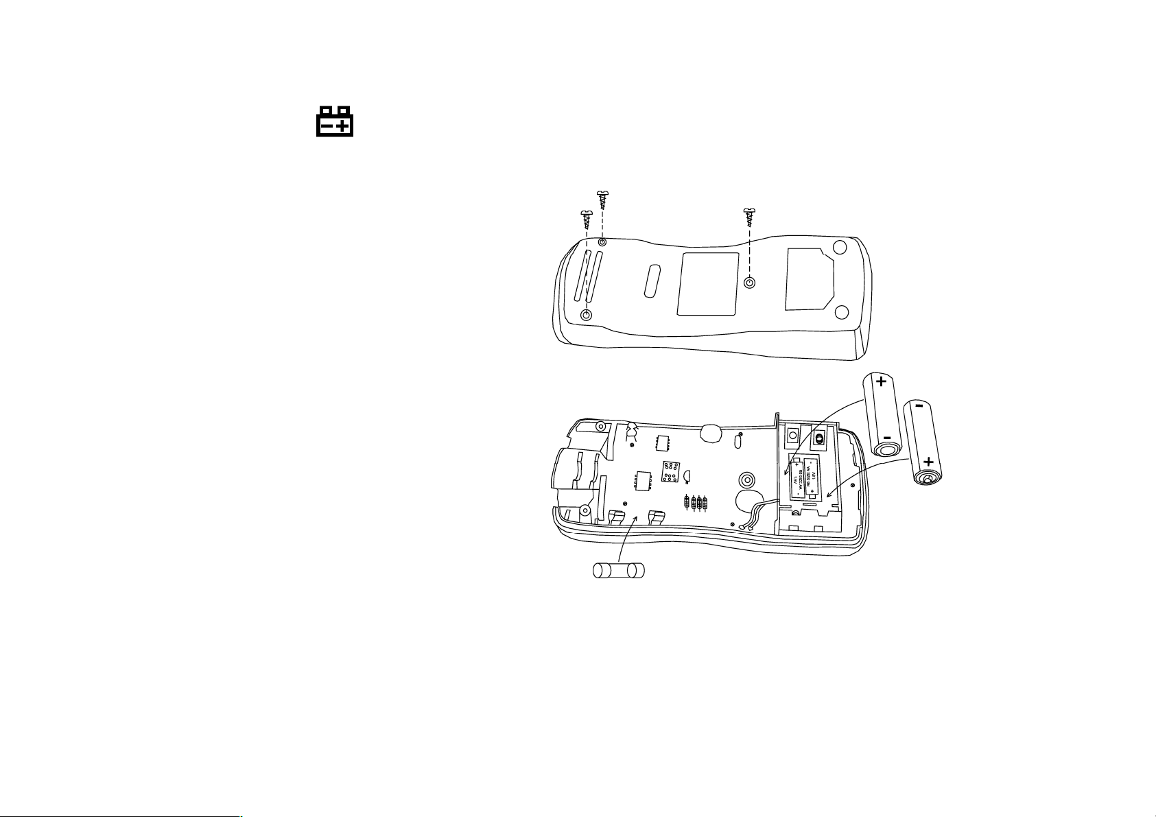
If the battery is weak, a " " symbol will appear on
the left of the display. It means that the battery should be replaced.
FUSE
10A /250V Fast Blow
Battery: 1.5V AA 2 pieces
or equivalent
Fuse 10A/250V Fast Blow
9
Page 11

Service and Parts
This DMM should be serviced only by a qualified service technician.
Specifications
Maximum Voltage: Between any Terminal and Earth Ground 600 V rms.
Display: 3 3/4-digits, 4000 counts, updates 3/sec.
Overload Indication: “OL” show on right up of the LCD.
Use environment: Temperature 32 to104°F (0°C to 40°C), humidity< 85% RH.
Storage environment : Temperature -4 to140°F (-20°C to 60°C), humidity< 95%RH,
Altitude: Operating under 2000m, Storage under 10,000m
Battery Type: Alkaline 1.5V AA 2 pieces or equivalent
Size (HxWxL): 3.36 cm (D) x 7.82 cm (W) x 15.8 cm (H) (1.32 in x 3.08 in x 6.22 in).
Weight: 290g (10 oz).
Safety standards: ( ETL / LVD ) . The meter is up to the standards of IEC1010 Pollution Degree 2,
Overvoltage Category Ⅲ. Rated 600Vac CATIII, Rated 1000Vdc CATII.
Accuracy is ± (% of reading + number in last digit) at 23 ± 5°C, <75% RH.
Temperature Coefficient: 0.1 %/°C
10
Page 12

At Smart Mode
Function Range Resolution Accuracy
ACV
DC V
4.000V
40.00V
400.0V
500V
±4.000 V
±40.00 V
±400.0 V
±500 V
400.0 Ω
4.000 kΩ
1 mV
10 mV
0.1 V
1 V
1 mV
10 mV
0.1 V
1 V
0.1 Ω
1 Ω
±(0.8% +3)
± (0.8% +3)
± (0.8% +3)
± (1.2% +3)
± (0.5% +3)
± (0.5% +3)
± (0.5% +3)
± (0.8% +3)
± (1% +5)
± (1% +3)
Ω
40.00 kΩ
400.0 kΩ
4.000 MΩ
10 Ω
0.1 k Ω
1 kΩ
± (1% +3)
± (1% +3)
± (1% +3)
11
Page 13

40.00 MΩ 10 kΩ ± (2% +3)
AC A
(50 to 400Hz)
DC A
Input maximum: 600Vrms
Current Measurement Overload Protection: 10A/250V Fuse.
005.0~400.0mA
4.000A
005.0~400.0mA
4.000A
At 3 Buttons Selecting Mode
Function Range Resolution Accuracy
400.0mV
4.000V
AC V
40.00V
(40 to 400Hz)
400.0V
0.1mA
1mA
0.1mA
1mA
0.1 mV
1 mV
10m V
0.1 V
± (2.5% +5)
± (2.5% +5)
± (2% +5)
± (2% +5)
±(1.2% +3)
± (0.8% +3)
± (0.8% +3)
± (0.8% +3)
500V
12
1V
± (1.2% +3)
Page 14

±400.0 mV
0.1 mV
± (0.5% +3)
DC V
Ω
AC A
(40 to 400Hz)
±4.000 V
±40.00 V
±400.0 V
±500 V
400.0 Ω
4.000 kΩ
40.00 kΩ
400.0 kΩ
4.000 MΩ
40.00 MΩ
005.0~400.0mA
4.000A
1 mV
10 mV
0.1 V
1 V
0.1 Ω
1 Ω
10 Ω
0.1 k Ω
1 kΩ
10 kΩ
0.1mA
1mA
± (0.5% +3)
± (0.5% +3)
± (0.5% +3)
± (0.8% +3)
± (1% +5)
± (1% +3)
± (1% +3)
± (1% +3)
± (1% +3)
± (2% +3)
± (2.5% +5)
± (2.5% +5)
005.0~400.0mA
DC A
4.000A
Capacity 40nF~40µF 10pF ± (3% +5)
0.1mA
1mA
± (2% +5)
± (2% +5)
13
Page 15

Continuity Less than 100Ω Approx.
Diode Test voltage : Approx. 2.8V
Input maximum: 600Vrms
400µF~4000µF 0.1µF ± (20% +5)
14
Page 16

15
 Loading...