

Page 1
MT-1280
3 1/2 Digital Multimeter
User’s Manual
st
1
Edition, 2013
©2013 Copyright by Prokit’s Industries Co., Ltd.
Page 2
ARIZE
SUMM
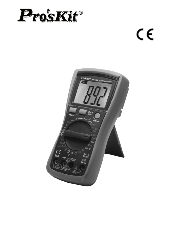
The meter is a stable multimeter with 26mm LCD display,
driven by battery. It’s widely used on measuring DCV, ACV,
DCA, ACA, resistance, capacitance, diode, transistor,
continuity test and temperature. Ideal for lab, factory and
family use.
SAFETY NOTE
The meter meets the standards of IEC1010. Read the
operation manual carefully before operation.
1. Do not input limit over-ranged.
2. The voltage below 36V is safety. To avoid electric shock,
check whether the test leads are connected correctly,
whether the insulation is good when measuring over
36DCV or 25ACV.
3. Remove the test leads when changing function and
range.
4. To select correct function and range, beware of error
operation.
5. Do not operate the meter if battery case and back cover is
not fixed.
6. Do not input voltage when measuring resistance.
7. Remove test leads from test point and turn off the power
before replacing battery and fuse.
8. SAFETY SYMBOLS
“
” indispensably refer to the manual, “ ” GND ,
“ " Double Insulation, “ ” low battery。
CHARACTERISTIC
1. GENERAL
1-1. Displaying: LCD displaying.
1-2. Max. displaying: 1999 (3 1/2digit) auto polarity indication.
1-3. Measuring method: dual slope A/D conversion.
1-4. Sampling rate: approx. 3 times/second.
1-5. Overrange indication: the LCD displays"1" or "-1".
1-6. Low battery indication:"
1-7. Operation environment: (0~40)˚C, R.H.<80% .
1
" appears.
Page 3
1-8. Power: 9V×1(NEDA1604/6F22 or equivalent model)
not included.
1-9. Size: 182×90×46mm
1-10. Weight: approx. 320g (Without Battery).
2. TECHNICAL CHARACTERISTIC
2-1. Accuracy: ±(a%×rdg+d) at (23±5°C)<R.H.<75%
2-2. TECHNICAL DATA
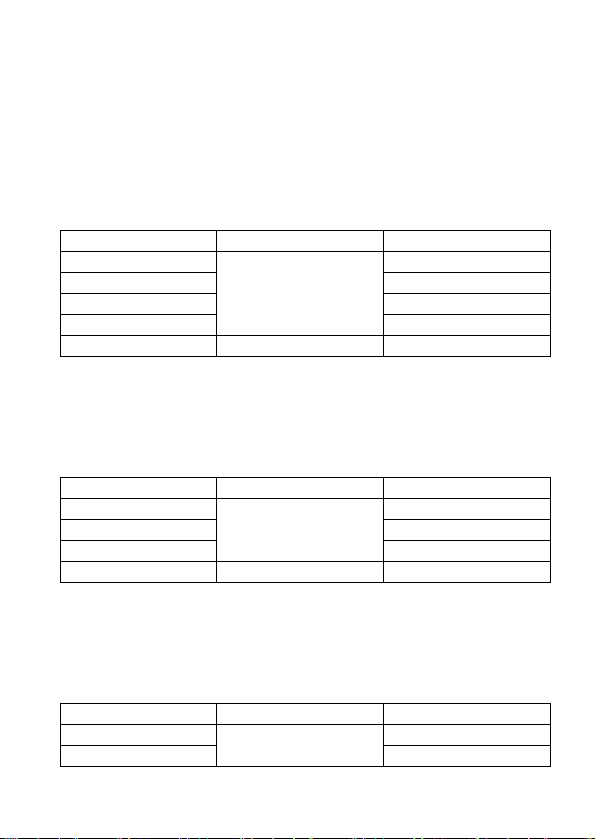
2-2-1. DCV
RANGE ACCURACY RESOLUTION
200mV 100uV
2V 1mV
20V 10mV
200V
1000V ±(0.8%+10d) 1V
• Input resistance: 10MΩ for all ranges.
• Overload protection: 250V DV or AC peak value at 200mV
range.
• 1000V DC or AC peak value at other ranges.
2-2-2. ACV
RANGE ACCURACY RESOLUTION
2V 1mV
20V 10mV
200V
750V ±(1.2%+10d) 1V
• Input resistance: 10MΩ
• Overload protection: 1000V DC or AC peak value
• Frequency response: (40~200)Hz
• Display: sine wave RMS (mean value response)
2-2-3.DCA
RANGE ACCURACY RESOLUTION
200uA 0.1uA
20mA
2
±(0.5%+3d)
±(0.8%+5d)
±(0.8%+10d)
100mV
100mV
10uA
Page 4
200mA ±(1.2%+
20A ±(2.0%+5d) 10mA
• Max. input volt drop: 200mV
• Max. input current: 20A (the test time should be in 10
seconds)
• 0.2A/250V Self-resettable fuse; 20A/250V fast-blown fuse
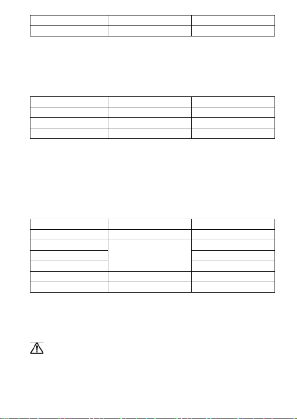
2-2-4.ACA
RANGE ACCURACY RESOLUTION
20mA ±(1.0%+5d) 10uA
200mA ±(2.0%+5d) 100uA
20A ±(3.0%+10d) 10mA
• Max. measuring volt drop: 200mV
• Max. input current: 20A (the test time should be in 10
seconds)
• 0.2A/250V Self-resettable fuse ; 20A/250V fast-blown fuse
• Frequency response: (40~200)Hz
• Display: sine wave RMS (mean value response)
2-2-5. RESISTANCE(Ω)
RANGE ACCURACY RESOLUTION
200Ω ±(0.8%+5d) 0.1Ω
2kΩ 1Ω
20kΩ 10Ω
200kΩ
20MΩ ±(1.0%+25d) 10kΩ
200MΩ ±(5.0%+10d) 100kΩ
• Open voltage: less than 0.7V
• Overload protection: 250V DC and AC peak value
NOTE: at 200Ω range, the test leads should be short-circuit,
and measure the down-lead resistance, then, subtract from
the real measuring.
WARNING: DO NOT input any voltage at resistance
range for safety!
2-2-6. CAPACITANCE (C)
3
±(0.8%+3d)
8d) 100uA
100Ω
Page 5
RANGE ACCURA
20nF 10pF
20uF
200uF
• Overload protection: 36V DC or AC peak value
WARNING: DO NOT input any voltage at this range for
safety!
2-2-7.TEMPERATURE(˚C)
RANGE ACCURACY RESOLUTION
(-20~1000)˚C < 400˚C±(1.0%+5d)
• Sensor: K-type thermocouple with banana plug
WARNING: DO NOT input any voltage at this range for
safety!
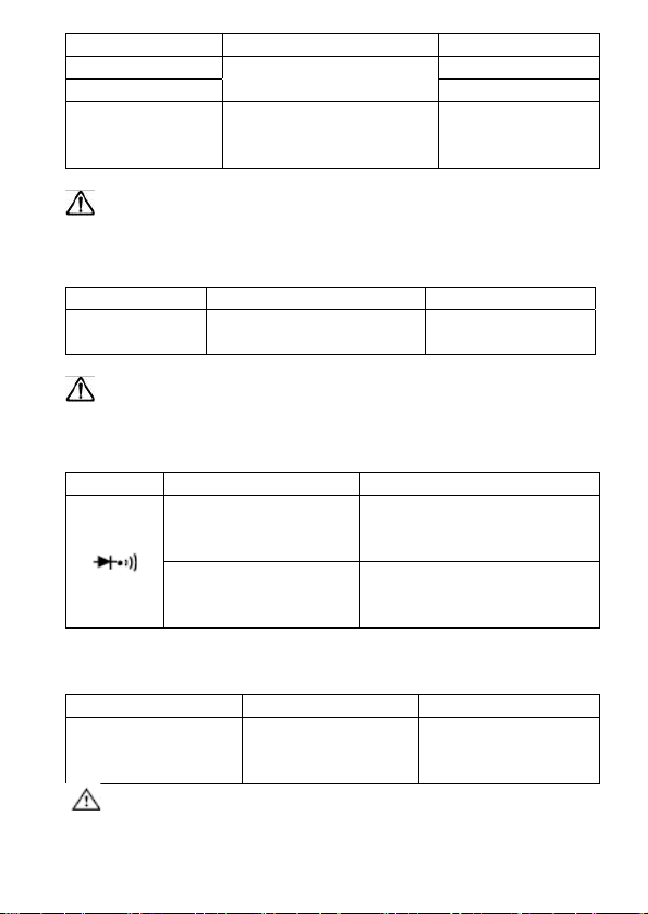
2-2-8.DIODE AND CONTINUITY TEST
Range Displaying value Test condition
• Overload protection: 250V DC or AC peak value
2-2-9. Triode hFE test
Range Displaying value Test condition
hFE NPN or PNP 0~1000 Basic current is
WARNING: DO NOT input any voltage at this range for
safety!
4
±(5.0%+20d)
>100uF (only for
reference)
≥ 400˚C±(1.5%+15d)
Positive voltage
drop of diode
Buzzer sounds , the
resistance is less
than (70±20)Ω
CY RESOLUTION
±(2.5%+20d)
The positive DC current
is approx. 1mA, negative
voltage is approx. 3V
open voltage is approx.
3V
10nF
100nF
1˚C
approx.10uA,Vce
is approx.3V
Page 6
ATION
OPER
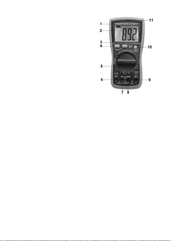
3.1 Front panel description
1. Mode
2. LCD display
3. Back light switch
4. Power switch
5. Range knob
6. 20A current jack
7. Less than 200mA current,
8. COM: capacitance,
9.
10. Hold switch
11. LED indicator light
3.2 DCV MEASUREMENT
1. Insert the black test lead to " COM " jack, the red one to
2. Set the range knob to a proper DCV range, connect the
NOTE:
1. If the measured voltage is unsure beforehand, should set
2. If LCD displays "1", it means overrange, should set the
3.3 ACV MEASUREMENT
1. Insert the black test lead to "COM " jack, the red one to
2. Set the range knob to a proper ACV range, connect the
5
l
Capacitance ,Temperature
“+”, HFE jack
temperature“-”, hFE test
accessory, diode,
continuity jack
Volt, resistance, diode and continuity jack
V/Ω jack.
test leads across to the circuit under tested, the polarity
and voltage of the point which red lead connect will
display on LCD.
the range knob to the highest range, then, switch to a
proper range according to the displayed value.
range knob to a higher range.
V/Ω jack.
Page 7

NOTE:
1. If the measured voltage is unsure beforehand, should set
the range knob to the highest range, then, switch to a
proper range according to the displayed value.
2. If LCD displays "1", it means overrange, should set the
range knob to a higher range.
3.4 DCA MEASUREMENT
1. Insert the black test lead to "COM " jack and the red one
to "mA" jack(max. 200mA) ,or insert the red one to "20A"
jack(max. 20A).
2. Set the range knob to a proper DCA range, connect the
test leads across to the circuit under tested, the current
value and polarity of the point which red lead connect will
display on LCD.
NOTE:
1. If the measured current is unsure beforehand, should set
the range knob to a higher range, then, switch to a proper
range according to the displayed value.
2. If LCD displays "1" , it means overrange, should set the
range knob to a higher range.
3. Max. input current is 200mA or 20A (subject to where red
lead insert), excessive current will blow the fuse. Be
careful when measuring. Continuously measuring large
current may heat the circuit, affect the accuracy, eve
damage the meter.
3.5 ACA MEASUREMENT
1. Insert the black test lead to "COM" jack and the red one to
"mA" jack(max. 200mA), or insert the red one to "20A"
jack (max. 20A).
2. Set the range knob to a proper ACA range; connect the
test leads across to the circuit under tested.
NOTE:
1. If the measured current range is unsure beforehand,
should set the range knob to the highest range, then set
6
Page 8

to a proper range according to the displayed value.
2. If LCD displays "1", it means overrange, should set the
range knob to a higher range.
3. Max. input current is 200mA or 20A (subject to where the
red lead insert to), excessive current will blow the fuse. Be
careful when measuring. Continuously measuring large
current may heat the circuit, affect the accuracy, even
damage the meter.
3.6 RESISTANCE MEASUREMENT
1. Insert the black test lead to "COM" jack and the red one to
"V/Ω" jack.
2. Set the range knob to a proper resistance range, connect
the test leads across to the resistance under measured.
NOTE:
1. If the resistance value being measured exceeds the max
value of the range selected, LCD displays "1", thus,
should set the range knob to a higher range. When the
resistance is over 1MΩ, the meter may take a few
seconds to stabilize. This is normal for high resistance
readings.
2. When input terminal is in open circuit, overload displays.
3. When measuring in-line resistance, be sure that power is
off and all capacitors are released completely.
3.7 CAPACITANCE MEASUREMENT
1. Insert the red test lead to " mA" terminal and the black one
to " COM " jack.
2. Set the range knob to a proper capacitance range,
connect the test leads to the capacitor under measured
(note: the polarity of red test lead is"+").
NOTE:
1. If the capacitance range under measured is unsure
beforehand, should set the range knob to the highest
range, then, set to a proper range according to the
displayed value.
2. If LCD displays "1" , it means overrange, should set the
7
Page 9

e knob to a higher range.
rang
3. Before measuring, LCD display might not be zero, the
residual reading will be decreased gradually and could be
disregarded.
4. When measuring large capacitance, if creeps seriously or
break capacitance, LCD will display some instability
value.
5. Discharge all capacitors completely before capacitance
measurement to avoid damage.
6. UNIT: 1uF =1000nF 1nF=1000pF
3.8 DIODE AND CONTINUITY TEST
1. Insert the black test lead to "COM" terminal and the red
one to "V/Ω" jack ( Note: the polarity of red test lead is"+").
2. Set the range knob to "
leads to the diode under measured, reading is the
approximation of the diode positive volt drop.
3. Connect the test leads to two points of the measured
circuit, if buzzer sounds, the resistance is lower than
approx. (70±20)Ω.
3.9 TEMPERATURE MEASUREMENT
Insert the cathode of thermocouple’s cold end to " COM" jack
and anode to " mA" terminal, put the working end on or in the
tested object, temperature value can be read on LCD in
Celsius.
3.10 TRIODE hFE
1. Set the range knob to hFE.
2. Insert the test accessory into “COM” and “mA” terminal.
3. Verify the type of the transistor is NPN or PNP, insert the
emitter, basic and collector to the proper jack on test
accessory.
3.11 AUTO POWER OFF
Stop working around 15 minutes, the instrument will auto off
and get into the sleeping mode. To restart the meter, press
8
" range, connect the test
Page 10

wer” button twice for back to working status.
“po
MAINTENANCE
It’s a precision meter, DO NOT try to verify the circuit
1. Beware of waterproof, dustproof and shockproof.
2. Do not operate and store the meter in the circumstance of
high temperature, high humidity, and flammability,
explosive and strong magnetic field.
3. Use the damp cloth and soft solvent to clean the meter, do
not use abrasive and alcohol.
4. If do not operate it for a long time, should take out the
battery.
4-1. When LCD displays "
battery as below:
4-1-1. Remove the battery compartment screws and pull
out the battery compartment.
4-1-2. Take out the battery and replace a new one. It’s
better to use alkalescency battery for long time
use.
4-1-3. Fix the battery case
" symbol, should replace the
If the meter does not work properly, check
the meter as following:
CONDITIONS WAY TO SOLVE
NO DISPLAYING Power is off
Replace battery
SYMBOL DISPLAYS Replace battery
NO CURRENT INPUT Replace fuse
VALUE ERROR Replace battery
9
Page 11

MT-1280 3 1/2 數位電錶
使用說明書
一、概述
MT-1280 儀錶是一種性能穩定、用電池驅動的高可靠性數位萬
用表。儀錶採用 26mm 字高 LCD 顯示器,讀數清晰、更加方便
使用。
此系列儀錶可用來測量直流電壓和交流電壓、直流電流和交流電
流、電阻、電容、二極體、三極管、通斷測試、溫度等參數。整
機以雙積分 A/D 轉換為核心,是一台性能優越的工具儀錶,是
實驗室、工廠及家庭理想工具。
二、安全事項
該系列儀錶在設計上符合 IEC1010 條款(國際電工委員會頒佈的
安全標準),在使用之前,請先認真閱讀說明書。
1. 各量程測量時,禁止輸入超過量程的極限值。
2. 36V 以下的電壓為安全電壓,在測高於 36V 直流、25V 交流
電壓時,要檢查錶棒是否可靠接觸,是否正確連接、是否絕
緣良好等,以避免電擊。
3. 換功能和量程時,錶棒應離開測試點。
4. 選擇正確的功能和量程,謹防誤操作,該系列儀錶雖然有全
量程保護功能,但為了安全起見,仍請您多加注意。
5. 在電池沒有裝好和後蓋沒有上緊時,請不要使用此表進行測
試工作。
6. 測量電阻時,請勿輸入電壓值。
7. 在更換電池或保險絲前,請將測試錶棒從測試點移開,並關
閉電源開關。
8. 安全符號說明:
“
"操作者必須參閱說明書“ "接地,“ "雙絕緣,
“ "低電壓符號。
10
Page 12

、特性
三
1. 一般特性
1-1. 顯示方式:LCD 液晶顯示
1-2. 最大顯示:1999(3 1/2 位)自動極性顯示
1-3. 測量方式:雙積分式 A/D 轉換
1-4. 採樣速率:約每秒鐘 3 次
1-5. 超量程顯示:最高位顯“1"或“-1"
1-6. 低電壓顯示:“
1-7. 工作環境:(0~40)℃,相對濕度<80%
1-8. 電源:一只 9V 電池(NEDA1604/6F22 或同等型號)
(不含電池)
1-9. 體積(尺寸):182×90×46mm (長×寬×高)
1-10. 重量:約 320g(不含電池)
1-11. 附件:使用說明書一本、外包裝盒、錶棒一副、K 型熱電偶
一支、電晶體/電容測試座。
2. 技術特性
2-1. 準確度:±(a%×讀數+字數),保證準確度環境溫度:
(23±5)°C,相對濕度<75%。
2-2. 測試功能︰直流電壓 DCV、 交流電壓 ACV.、直流電流
DCA、交流電流 ACA、電阻 Ω、二極體/通斷、電容 C、
溫度 °C、三極管 hFE
2-3.技術指標
2-3-1.直流電壓(DCV)
量程 準確度 分辨力
200mV 100uV
2V 1mV
20V 10mV
200V
1000V ±(0.8%+10d) 1V
‧輸入阻抗:所有量程為 10MΩ
‧超載保護:200mV 量程為 250V 直流或交流峰值;其餘為 1000V
直流或交流峰值。
11
"符號出現
±(0.5%+3d)
100mV
Page 13

2-3-2.交流電壓(ACV)
量程 準確度 分辨力
2V 1mV
20V 10mV
200V
750V ±(1.2%+10d) 1V
‧輸入阻抗:10MΩ
‧超載保護:1000V 直流或交流峰值;
‧頻率回應:40~200Hz
‧顯 示:正弦波有效值(平均值響應)。
2-3-3.直流電流(DCA)
量程 準確度 分辨力
200uA 0.1uA
20mA
200mA ±(1.2%+8d) 100uA
20A ±(2.0%+5d) 10mA
‧最大輸入壓降:200mV
‧最大輸入電流:20A(測試時間不超過 10 秒)
‧0.2A/250V 自恢復保險絲;20A/250V 速熔保險絲。
2-3-4.交流電流(ACA)
量程 準確度 分辨力
20mA ±(1.0%+5d) 10uA
200mA ±(2.0%+5d) 100uA
20A ±(3.0%+10d) 10mA
‧最大測量壓降:200mV
‧最大輸入電流:20A(測試時間不超過 10 秒)
‧頻率回應:(40~200)Hz
‧顯 示: 正弦波有效值(平均值響應)。
‧0.2A/250V 自恢復保險絲;20A/250V 速熔保險絲。
±(0.8%+5d)
±(0.8%+10d)
100mV
10uA
12
Page 14

電阻(Ω)
2-3-5.
量程 準確度 分辨力
200Ω ±(0.8%+5d) 0.1Ω
2kΩ 1Ω
20kΩ 10Ω
200kΩ
±(0.8%+3d)
100Ω
20MΩ ±(1.0%+25d) 10kΩ
200MΩ ±(5.0%+10d) 100kΩ
‧開路電壓:小於 0.7V
‧超載保護:250V 直流和交流峰值;
‧注意事項:在使用 200Ω 量程時,應先將錶棒短路,測得引線
電阻,然後在實測中減去;
警 告:為了安全在電阻量程禁止輸入電壓值!
2-3-6.電容(C)
量程 準確度 分辨力
20nF 10pF
20uF
200uF
±(2.5%+20d)
±(5.0%+20d)
>100uF(僅供參考)
10nF
100nF
超載保護:36V 直流或交流峰值。
警 告:為了安全在此量程禁止輸入電壓值!
2-3-7.溫度(℃)
量程 準確度 分辨力
(-20~1000)˚C < 400˚C±(1.0%+5d)
1˚C
≥ 400˚C±(1.5%+15d)
‧感測器:K 型熱電偶(鎳鉻—鎳硅)香蕉插頭。
警 告:為了安全在此量程禁止輸入電壓值!
2-3-8.二極體及通斷測試
量程 顯示值 測試條件
二極體正向壓降 正向直流電流約1mA, 反
蜂鳴器發聲長響,測 開路電壓約 3V
向電壓約 3V
13
Page 15

試兩
點阻值小於
試兩 點阻值小於
(70±20)Ω
(70±20)Ω
超載保護:250V 直流或交流峰值
2-3-9.晶體三極管 hFE 參數測試
量程 顯示值 測試條件
hFE NPN 或 PNP 0~1000 基礎電流約 10uA,
Vce 約為 3V
警 告:為了安全在此量程禁止輸入電壓值!
四、使用方法
操作面牌說明
1. 產品型號
2. 液晶顯示面板
3. 背光照明按鍵
4. 電源開關按鍵
5. 旋鈕開關:選擇測量功能及量程
6. 20A 電流測試插座
7. 小於 200mA 電流測試, 電容, 溫
度“+", 電晶體測試插座
8. 公共端: 電壓、電阻、電容、溫
度“-"負極, 電晶體,通斷及二
極體測試插座
9. 電壓、電阻、通斷及二極體測試
插座
10. 數據保持按鍵
11. LED 指示燈
直流電壓測量
1. 將黑錶棒插入“COM"插座,紅錶棒插入“V/Ω"插座;
2. 將量程開關轉至相應的 DCV 量程上,然後將測試錶棒跨接
在被測電路上,紅錶棒所接的該點電壓與極性顯示在螢幕
上。
注意:
1. 如果事先對被測電壓範圍沒有概念,應將量程開關轉到最高
的檔位元,然後根據顯示值轉至相應檔位上;
1414
Page 16

2. 如螢幕顯“1",表明已超過量程範圍,須將量程開關轉至
較高檔位元上。
交流電
壓測量
1. 將黑錶棒插入“COM"插座,紅錶棒插入“V/Ω"插座;
2. 將量程開關轉至相應的 ACV 量程上,然後將測試錶棒跨接
在被測電路上。
注意:
1. 如果事先對被測電壓範圍沒有概念,應將量程開關轉到最高
的檔位元,然後根據顯示值轉至相應檔位上。
2. 如螢幕顯“1",表明已超過量程範圍,須將量程開關轉至
較高檔位上。
直流電流測量
1. 將黑錶棒插入“COM"插座,紅錶棒插入“mA"插座中(最
大為 200mA),或紅錶棒插入“20A"插座中(最大為 20A)
2. 將量程開關轉至相應 DCA 檔位上,然後將儀錶的錶棒串聯
接入被測電路中,被測電流值及紅色錶棒點的電流極性將同
時顯示在螢幕上。
注意:
1. 如果事先對被測電流範圍沒有概念,應將量程開關轉至較高
檔位,然後按顯示值轉至相應檔上 。
2. 如螢幕顯“1",表明已超過量程範圍,須將量程開關轉至
較高檔位上 。
3. 持續量測大電流可能會造成產品損壞。
交流電流測量
1. 將黑錶棒插入“COM"插座,紅錶棒插入“mA"插座中(最
大為 200mA),或紅錶棒插入“20A"插座中(最大為 20A)
2. 將量程開關轉至相應 ACA 檔位上,然後將儀錶的錶棒串聯
接入被測電路中。
注意:
1. 如果事先對被測電流範圍沒有概念,應將量程開關轉到最高
的檔位,然後按顯示值轉至相應檔上。
2. 如螢幕顯“1",表明已超過量程範圍,須將量程開關轉至
較高的檔位上。
3. 持續量測大電流可能會造成產品損壞。
15
Page 17

電
阻測量
1. 將黑錶棒插入“COM"插座,紅錶棒插入“V/Ω"插座;
2. 將量程開關轉至相應的電阻量程上,然後將兩錶棒跨接在被
測電阻上。
注意:
1. 如果電阻值超過所選的量程值,則會顯“1",這時應將開
關轉至較高檔位上;當測量電阻值超過 1MΩ 以上時,讀數
需幾秒時間才能穩定,這在測量高電阻時是正常的。
2. 當輸入端開路時,則顯示超載情形。
3. 測量線上電阻時,要確認被測電路所有電源已關斷及所有電
容都已完全放電時,才可進行。
電容測量
1. 將紅錶棒插入“mA"插座,黑錶棒插入“COM"插座;
2. 將量程開關轉至相應之電容量程上,錶棒對應極性(注意紅
錶棒極性為“+"極)接入被測電容。
注意:
1. 如果事先對被測電容範圍沒有概念,應將量程開關轉到最高
的檔位;然後根據顯示值轉至相應檔位上。
2. 如螢幕顯“1",表明已超過量程範圍,須將量程開關轉至
較高的檔位上。
3. 在測試電容前,螢幕顯示值可能尚未回到零,殘留讀數會逐
漸減小,但可以不予理會,它不會影響測量的準確度;
4. 大電容檔測量嚴重漏電或擊穿電容時,將顯示一些數值且不
穩定。
5. 請在測試電容容量之前,必須對電容應充分地放電,以防止
損壞儀錶。
6. 單位:1uF =1000nF 1nF=1000pF
二極體及通斷測試
1. 將黑錶棒插入“COM"插座,紅錶棒入“V/Ω"插座(注
意紅表筆極性為“+"極)。
2. 將量程開關轉至“
體,讀數為二極體正向壓降的近似值 。
3. 將錶棒連接到待測線路的兩點,如果兩點之間電阻值低於約
(70±20)Ω,則內置蜂鳴器發聲
16
"檔,並將錶棒連接到待測試二極
Page 18

溫
度測量
測量溫度時,將熱電偶感測器的冷端(自由端)負極插入
“COM"插座,正極插入“mA"插座中,熱電偶的工作端(測
溫端)置於待測物上面或內部,可直接從螢幕上讀取溫度值,讀
數為攝氏度。
三極管 hFE
1. 將量程開關置於 hFE 檔;
2. 將電晶體測試座插入“COM"和“mA"插座.
3. 確定所測電晶體為 NPN 或 PNP 型,將發射極、基極、集電
極分別插入測試附件上相應的插孔。
自動關機
當儀錶靜置 15 分鐘後,儀錶便自動斷電進入休眠狀態;若要
重新啟動電源,再按兩次“POWER"鍵,就可重新接通電源。
五、儀錶保養
該系列儀錶是一台精密儀器,使用者不要隨意更改電路。
1. 請注意防水、防塵、防摔;
2. 不宜在高溫高濕、易燃易爆和強磁場的環境下存放、使用儀
錶;
3. 請使用濕布和溫和的清潔劑清潔儀錶外表,不要使用研磨劑
及酒精等烈性溶劑;
4. 如果長時間不使用,應取出電池,防止電池漏液腐蝕儀錶;
4-1. 注意 9V 電池使用情況,當螢幕顯示出“
更換電池,步驟如下:
A) 卸下電池盒固定螺絲,退出電池盒;
B) 取下 9V 電池,換上一個新的電池,雖然任何標準9V 電
池都可使用,但為加長使用時間,最好使用鹼性電池;
C) 裝上電池門。
"符號時,應
17
Page 19

障排除
六、故
如果您的儀錶不能正常工作,下面的方法可以幫助您快速解決一
般問題。如果故障仍排除不了,請與維修中心或經銷商聯繫。
故障現象 檢 查 部 位 及 方 法
沒顯示 電源未接通
換電池
換保險絲
符號出現 換電池
顯示誤差大 換電池
‧本說明書如有改變,恕不通知;
‧本說明書的內容被認為是正確的,若用戶發現有錯誤、遺漏
等,請與生產廠家聯繫。
‧本公司不承擔由於用戶錯誤操作所引起的事故和危害。
‧本說明書所講述的功能,不作為將產品用做特殊用途的理由。
18
Page 20

19
 Loading...