

Page 1
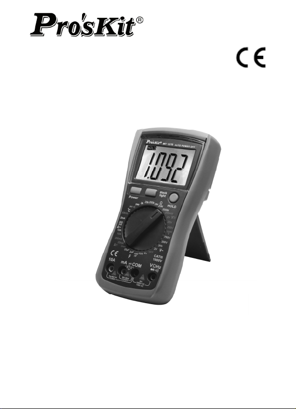
MT-1270
3 1/2 Digital Multimeter
User’s Manual
st
1
Edition, 2013
©2013 Copyright by Prokit’s Industries Co., Ltd.
Page 2

Genera
l
This instrument is a high performance and accuracy digital
multimeter driven by 9V battery. It uses the LCD with 26mm high
figure to make the reading clear and the operation more
convenient.
This instrument can measure DC and AC Voltage, DC and AC
Current, Resistance, Capacitance, Frequency, Diode, Transistor,
Continuity, Temperature, etc. It is an excellent instrument with the
dual-integral A/D converter as core, mostly suitable for lab, factory,
maintenance and repair users.
Safety Note
This instrument meets the standard of IEC1010 (safety standard
promulgated by International Electrician Committee), please read
the safety notes carefully before operation.
1. Do not input the value over the range limit when measuring
each range.
2. The safety voltage is below 36V, please make sure the test
leads connect reliably, link up correctly, isolate properly to
avoid electric shock when measuring the voltage higher than
36V DC or 25V AC.
3. Please make sure the test leads off the tested point when
converting the function and range.
4. Please select the correct function and range to avoid the fault
operation. Even through the instrument has full protection
function; please pay high attention when measuring for safety.
5. Do not operate the instrument before the battery is fixed on
properly and battery compartment is screwed tightly.
6. Do not input the voltage when measuring the resistance.
7. Please make sure the test leads off the tested point and the
power is turned off before replacing the battery or fuse.
Safety Note Description:
” indispensably refer to the manual, “ ” GND ,
“
“ ” Double Insulation, “ ” low battery。
1
Page 3
Property
1. General Properly
1-1. Display: LCD
1-2. Max display: 1999 (3 1/2 digit) automatic polarity display.
1-3. Measuring method: dual-integral A/D converter
1-4. Sampling Rage: approx. 3 times / sec.
1-5. Overrange display: LCD displays “1” or “-1”
1-6. Low battery display: “
1-7. Operation environment: (0~40)℃,Relative humidity: <80%
1-8. Power: a 9V battery (NEDA1604/6F22 or equivalent)
1-9. Dimension: 182 x 90 x 46 mm
1-10. Weight: approx. 320g (Not including 9V battery)
1-11. Accessory: user manual, CAT III test leads, temperature
Technical Property
2-1.Accuracy: ±(a% x reading + digits) at (23±5)℃, relative
2-2.Functions: DC and AC Voltage, DC and AC Current,
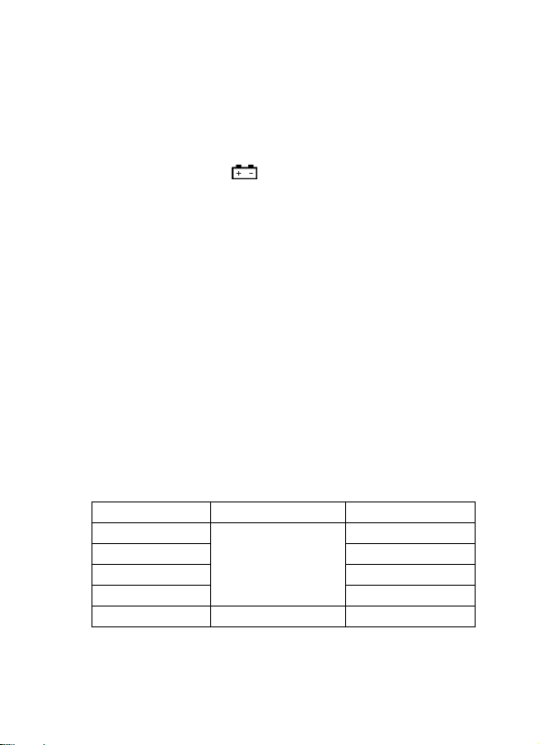
2-3-1.(DCV)
Input Impedance: 10 MΩ at all the ranges.
Overload protection: 250V DC or AC peak value at Range
200mV, 1000V DC or AC peak value at other Ranges.
”symbol appearance
probe, test socket
humidity <75%, one year calibration guarantee since the time
dispatched form the manufactory.
Resistance, Capacitance, Frequency, Diode, Transistor,
Continuity, Temperature, Backlight, Auto power off, Overload
protection, Low battery indication
Range Accuracy Resolution
200mV 100uV
2V 1mV
20V 10mV
200V
1000V ±(0.8%+10d) 1V
±(0.5%+3d)
100mV
2
Page 4
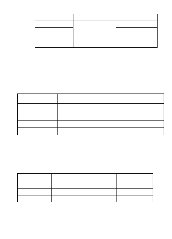
2-3-2.(ACV)
Range Accuracy Resolution
2V 1mV
20V 10mV
200V
750V ±(1.2%+10d) 1V
Input Impedance: 10 MΩ at all the ranges.
Overload protection: 1000V DC or AC peak value.
Frequency Response: (40~200)Hz at the Range below 20V
(40~100)Hz at the Range 200V~750V
Display: average value response (RMS of sine wave)
2-3-3.(DCA)
Range Accuracy Resolution
2mA 1uA
20mA
200mA ±(1.2%+8d) 100uA
10A ±(2.0%+5d) 10mA
Max input voltage drop: 200mV
Max input current: 10A (less than 10 seconds)
Overload protection: 0.2A/250V self-resettable fuse, 10A/250V
fast-blown fuse
2-3-4.(ACA)
Range Accuracy Resolution
20mA ±(1.0%+15d) 10uA
200mA ±(2.0%+5d) 100uA
10A ±(3.0%+10d) 10mA
Max measurement voltage drop: 200mV
Max input current: 10A (less than 10 seconds)
Overload protection: 0.2A/250V self-resettable fuse, 10A/250V
±(0.8%+5d)
100mV
±(0.8%+10d)
10uA
3
Page 5
fast-blo
wn fuse
Frequency response: (40~200)Hz
Display: average value response (RMS of sine wave)
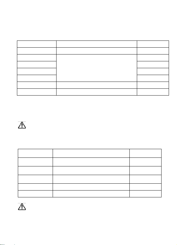
2-3-5.(Ω)
Range Accuracy Resolution
200Ω ±(0.8%+5d) 0.1Ω
2kΩ 1Ω
20kΩ 10Ω
200kΩ 100Ω
2MΩ
20MΩ ±(1.0%+25d) 10kΩ
200MΩ ±(5.0%+30d) 100kΩ
Open circuit voltage: less than 0.7V
Overload protection: 250V DC and AC peak value.
Note: At Range 200Ω, short-circuit the test lead to test the wire
resistance, and then subtract it from the real measurement.
WARNING: DO NOT input any voltage at resistance
range for safety!
2-3-6.(C)
Range Accuracy Resolution
2nF ±(2.5%+20d) 1pF
20nF ±(2.5%+20d) 10pF
200nF ±(2.5%+20d) 100pF
2uF ±(2.5%+20d) 1nF
20uF ±(5.0%+10d) 10nF
• Overload protection: 36V DC or AC peak value
WARNING: DO NOT input any voltage at this range for
safety!
±(0.8%+3d)
1kΩ
4
Page 6
2-3-7.(f)
Range Accurac
y Resolution
20kHz ±(3.0%+18d) 10Hz
Input sensitivity: 1V RMS value
Overload protection: 250V DC or AC peak value (less than 15
seconds)
2-3-8.(℃)
Range
Accuracy
Accuracy
Resolution
(-20~400)℃ ±(1.0%+5d) 1℃
(400~1000)℃ ±(1.5%+15d) 1℃
Sensor: K Type Thermocouple, banana plug
WARNING: DO NOT input any voltage at this range for
safety!
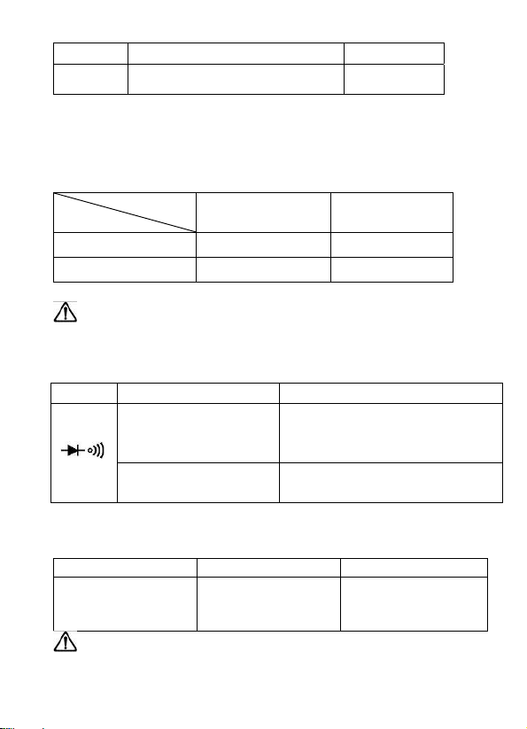
2-3-9.Diode and Continuity Test
Range Description Test Condition
Forward voltage
drop of diode
Buzzer sound at
less than(70±20)Ω
Forward DC Current approx.
1mA,Counter Voltage
approx. 3V
Open-circuit voltage approx.
3V
Overload protection: 250V DC or AC peak value.
2-2-10. Triode hFE test
Range Displaying value Test condition
hFE NPN or PNP 0~1000 Basic current is
approx.10uA,Vce
is approx.3V
WARNING: DO NOT input any voltage at this range for
safety!
5
Page 7
Ope
ration Method
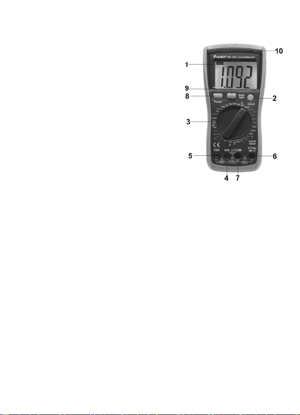
1. Front Panel Description
1. LCD: Display the measuring
value
HOLD Key: Press the key,
2.
the present measuring value
is held on LCD, and appear
“Hold” symbol, press the key
again, disappear “Hold”
symbol, and exist the Date
Hold function
3. Range Knob: Switch the
measuring function and
range
4. Less than 200mA
current ,Capacitance ,Tempe
+” ,HFE measuring terminal
rature“
5. 10A current measuring terminal
6. Voltage, Resistance, and diode, Continuity, Frequency
measuring terminal
7. In common terminal, Capacitance, Temperature“
-”, HFE,
Frequency measuring terminal
8. Power switch: Power on/off
9. Backlight switch
10. LED indicator light
2. DCV Measurement
1. Insert the black lead into the “COM” terminal, and the red
lead into “V/Ω/Hz” the terminal
2. Tern the range knob to the DCV Range, then connect the
test leads cross the tested circuit, the voltage and polarity
of the tested point connected by the red test lead are
displayed on LCD.
Note:
1
. If the tested voltage is unknown beforehand, should turn
6
Page 8

2. If LCD displays “1”, it indicates overload, should turn the
knob to the higher range.
3. ACV Measurement
1. Insert the black lead into “COM” terminal, and the red lead
into “V/Ω/Hz” terminal, turn the knob to the ACV range,
then connect the test leads across the tested circuit.
Note:
1. If the tested voltage is unknown beforehand, should turn
the knob to the highest range, and then turn to the relative
range according to the value displayed on LCD.
2. If LCD displays “1”, it indicates overload, should turn the
knob to the higher range.
4. DCA Measurement
1. Insert the black lead into “COM” terminal, and red lead into
“mA” terminal (Max 200mA) or red lead into “10A”
terminal(Max 10A)
2. Tern the knob to the DCA Range, then connect the test
leads into the tested circuit in series, the tested current
value and polarity of the red lead will be displayed on LCD
simultaneously.
Note:
1. If the tested current is unknown beforehand, should turn
the knob to the highest range, and then turn to the relative
range according to the value displayed on LCD
2. If LCD displays “1”, it indicates overload, should turn the
knob to the higher range.
3
. The max input current is 200mA or 10A, it depends on the
location the red lead is inserted. When measuring 10A,
note it will affect the accuracy of measurement and
damage the instrument to continuously measure large
current to make the circuit heat
7
Page 9

5. ACA Measurement
1. Insert the black lead into “COM” terminal, and red lead into
“mA” terminal (max 200 mA), or red lead into “10A” terminal
(max 10A)
2. Tern the knob to the ACA Range, then connect the test
leads into the tested circuit in series.
Note:
1. If the tested current is unknown beforehand, should turn
the knob to the highest range, and then turn to the relative
range according to the value displayed on LCD.
2. If LCD displays “1”, it indicates overload, should turn the
knob to the higher range
3. The max input current is 200mA or 10A, it depends on the
location the red lead is inserted. When measuring 10A,
note it will affect the accuracy of measurement and
damage the instrument to continuously measure large
current to make the circuit heat
6. Resistance Measurement
1. Insert the black lead into “COM” terminal, and red lead into
“V/Ω/Hz” terminal
2. Turn the knob to the Resistance Range, then connect the
test leads across the tested circuit
Note:
1. If the tested value exceeds the range selected, LCD
displays “1”, should turn the knob to higher range; When
the tested value exceeds 1MΩ, it is normal to take several
seconds to make the reading stable.
2. When the input terminal is open circuit, LCD displays the
status of overload.
3. When measuring in-circuit resistance, to make sure the
power of the tested circuit has been turned off and all the
capacitors has been discharged completely.
8
Page 10

7. Capacitance Measurement
1. Insert the red lead into “mA” terminal, and black lead into
“COM” terminal
2. Turn the knob to the Capacitance Range, then connect the
test leads across the tested capacitance (note the polarity
of the red lead is positive)
Note:
1. If the tested capacitor is unknown beforehand, should turn
the knob to the highest range,
2. and then turn to the relative range according to the value
displayed on LCD
3. If LCD displays “1”, it indicates overload, should turn the
knob to the higher range
4. Before measuring capacitor, it is possible the display on
LCD doesn’t return to zero, the reading on LCD will
gradually approach zero, please ignore it, it doesn’t affect
the accuracy of measurement.
5. When severe creepage or capacitor breakdown measured
at large capacitance range, LCD will display some value
unstably.
6. Before measuring capacitor, should completely discharge
the capacitor to avoid damaging the instrument.
7. 1uF =1000nF 1nF=1000pF
8. Frequency Measurement
1. Insert the leads or shield cable into “COM” and “V/Ω/Hz”
terminals.
2. Turn the knob to the Frequency Range, then connect the
test leads or cable across the signal source or tested load.
3. When input more 10Vrms, reading is available, but it is
possible to be out of specification.
4. In noisy environment, it is preferable to use shield cable
when measuring small signal
5
. Caution to avoid touching the high voltage circuit when
9
Page 11

measuri
6. Do not input more than 250V DC or AC peak value to avoid
damaging the instrument.
9. .Diode and Continuity Test
1. Insert the black lead into “COM” terminal, and red lead into
“V/Ω/Hz” terminal (Note: the polarity of red lead is positive)
2. Turn the knob to the “
leads across the tested diode, the reading is the
approximation of the diode forward voltage drop.
3. Connect the test leads to the two points of the tested circuit,
if the value of resistance between the two points is less
than (70±20)Ω, the buzzer inside sounds
10. Temperature Measurement
When measuring Temperature, input the negative pole of
the thermocouple sensor into “COM” terminal, and positive
pole into “mA” terminal, connect the working side of the
thermocouple to the surface or inside of the tested subject,
to read the Fahrenheit temperature from LCD directly.
11. TRIODE hFE
1. Set the range knob to hFE.
2. Insert the test accessory into “COM” and “mA” terminal.
3. Verify the type of the transistor is NPN or PNP, insert the
12. Data Hold
Press the HOLD key, the present data is held on LCD.
13. Auto Power Off
Stop working around 15 minutes, the instrument will auto
off and get into the sleeping mode.
ng the high voltage circuit.
” Range, then connect the test
emitter, basic and collector to the proper jack on test
accessory.
10
Page 12

Maintenance
T
his is a high precise instrument; do not try to modify the inner
circuit at will.
1. Keep the instrument dry, and keep it away from dust and
shock
2. Do not store and use the instrument in high humility, high
temperature, combustible, explosive and strong magnetic
places.
3. Clean the instrument with the damp cloth and gentle
detergent, do not use the strong solvent like the abrasive
cleaner and alcohol, etc.
4. Take out the battery if not use the instrument for a long time
to prevent the battery leaking and the liquid to corrode the
instrument.
4-1. Note the status of the battery consumption, when LCD
displays “
the following steps:
4-1-1.Open the battery compartment
4-1-2.Remove the 9V battery, and replace it by same
4-1-3. Fit on the battery compartment
“symbol, should replace the batteries as
type new battery. It is better to use alkaline
batteries for longer service time.
11
Page 13

F
AULT ELIMINATION
If the instrument does not work properly, the below methods can
help you to solve the problems quickly. If the fault still can’t be
eliminated, please contact the maintenance center or the
distributors:
Fault Solution
Power off –pls turn on the power
No display
symbol
appearance
No current input Replace fuse
Error value Replace battery
1. The user manual is subject to change without notice
2. The contents in the user’s manual are considered to be
correct, if the user find any error or pretermissions, etc.,
please contact the manufacturer.
3. The manufacturer hereby will not be responsible for any
accident and damage caused by the improper operation.
4. The functions described in this instruction manual do not be
the reason for special usage.
Hold Key-pls set a correct mode
Replace battery
Replace battery
12
Page 14

MT-1270 3 1/2 數位電錶
使用說明書
一、概述
該系列儀錶是一種性能穩定、用電池驅動的高可靠性數位萬用表。
儀錶採用 26mm 字高 LCD 顯示器,讀數清晰、更加方便使用。
此系列儀錶可用來測量直流電壓和交流電壓、直流電流和交流電
流、電阻、電容、頻率、二極體、三極管、通斷測試、溫度等參數。
整機以雙積分 A/D 轉換為核心,是一台性能優越的工具儀錶,是實
驗室、工廠、無線電愛好者及家庭理想工具。
二、安全事項
1. 該系列儀錶在設計上符合 IEC1010 條款(國際電工委員會頒佈
的安全標準),在使用之前,請先閱讀安全注意事項。
2. 各量程測量時,禁止輸入超過量程的極限值;36V 以下的電壓
為安全電壓,在測高於 36V 直流、25V 交流電壓時,要檢查錶
棒是否可靠接觸,是否正確連接、是否絕緣良好,以避免電擊。
3. 換功能和量程時,錶棒應離開測試點。
4. 選擇正確的功能和量程,謹防誤操作,該系列儀錶雖然有全量
程保護功能,但為了安全起見,仍請您多加注意。
5. 在電池沒有裝好和後蓋沒有上緊時,請不要使用此表進行測試
工作。
6. 測量電阻時,請勿輸入電壓值。
7. 在更換電池或保險絲前,請將測試錶棒從測試點移開,並關閉
電源開關;
8. 安全符號說明:
"操作者必須參閱說明書“ "接地,“ "雙絕緣,
“
“ "低電壓符號。
13
Page 15

三、
特性
1.一般特性
1-1.顯示方式:LCD 液晶顯示;
1-2.最大顯示:1999(3 1/2 位元)自動極性顯示;
1-3.測量方式:雙積分式 A/D 轉換;
1-4.採樣速率:約每秒鐘 3 次;
1-5.超量程顯示:最高位顯“1"或“-1";
1-6.低電壓顯示:“
"符號出現;
1-7.工作環境:(0~40)℃,相對濕度<80% ;
1-8.電源:9V 電池(NEDA1604/6F22 或同等型號);
1-9.體積(尺寸):182 x 90 x 46 (長×寬×高);
1-10.重量:約 320 g(不含 9V 電池);
1-11.附件:使用說明書一本,CATIII 錶棒一付、溫度探棒一付。
電晶體/電容測試座
2.技術特性
2-1.準確度:±(a%×讀數+字數),保證準確度環境溫度:(23±5)℃,相
對濕度<75%。
2-2.功能︰ 直流電壓和交流電壓、直流電流和交流電流、電阻、電
容、頻率、二極體、三極管、通斷測試、溫度,自動關機,背
光照明,過流、過壓保護,低電池電力指示
2-3-1.直流電壓(DCV)
準確度
量程
準確度
分辨力
200mV 100uV
2V 1mV
20V 10mV
200V
±(0.5%+3d)
100mV
1000V ±(0.8%+10d) 1V
輸入阻抗:所有量程為 10MΩ;
超載保護:200mV 量程為 250V 直流或交流峰值;
其餘為 1000V 直流或交流峰值。
14
Page 16

2-3-2.交流電壓(ACV)
準確度
量程
2V 1mV
20V 10mV
±(0.8%+5d)
200V
準確度
分辨力
100mV
750V ±(1.2%+10d) 1V
輸入阻抗:所有量程為 10MΩ;
超載保護:1000V 直流或交流峰值;
頻率回應:20V 以下量程:(40~200)Hz,
200V~750V 量程:(40~100)Hz;
顯 示:正弦波有效值(平均值回應)。
2-3-3.直流電流(DCA)
準確度
量程
2mA 1uA
±(0.8%+10d)
20mA
200mA
10A
±(1.2%+8d)
±(2.0%+5d)
準確度
分辨力
10uA
100uA
10mA
最大輸入壓降:200mV;
最大輸入電流:10A(測試時間不超過 10 秒);
超載保護:0.2A/250V 自恢復保險絲,10A/250V 速熔保險絲。
2-3-4.交流電流(ACA)
準確度
準確度
分辨力
量程
20mA ±(1.0%+15d) 10uA
200mA ±(2.0%+5d) 100uA
10A ±(3.0%+10d) 10mA
最大測量壓降:200mV;
最大輸入電流:10A(測試時間不超過 10 秒);
15
Page 17

超載保護:0.2
A/250V 自恢復保險絲,10A/250V 速熔保險絲;
頻率回應:(40~200)Hz;
顯 示:正弦波有效值(平均值回應)。
2-3-5.電阻(Ω)
準確度
量程
準確度
分辨力
200Ω ±(0.8%+5d) 0.1Ω
2kΩ 1Ω
20kΩ 10Ω
200kΩ 100Ω
2MΩ
±(0.8%+3d)
1kΩ
20MΩ ±(1.0%+25d) 10kΩ
200MΩ ±(5.0%+30d) 100kΩ
開路電壓:小於 0.7V;
超載保護:250V 直流和交流峰值;
注意事項:在使用 200Ω 量程時,應先將錶棒短路,測得引線電
阻,然後在實測中減去;
警 告:為了安全在電阻量程禁止輸入電壓值!
2-3-6.電容(C)
量程
準確度
準確度
分辨力
2nF ±(2.5%+20d) 1 pF
20nF ±(2.5%+20d) 10pF
200nF ±(2.5%+20d) 100pF
2uF ±(2.5%+20d) 1nF
20uF ±(5.0%+10d) 10nF
超載保護:36V 直流或交流峰值。
警 告:為了安全在此量程禁止輸入電壓值!
16
Page 18

2-3-7.頻率(freq)
量 程 准 確 度 分辨力
20kHz ±(3.0%+18d) 10Hz
輸入靈敏度:1V 有效值;
超載保護:250V 直流或交流峰值(不超過 15 秒)。
2-3-8.溫度(℃)
準確度
量程
準確度
分辨力
(-20~400)℃ ±(1.0%+5d) 1℃
(400~1000)℃ ±(1.5%+15d) 1℃
感測器:K 型熱電偶(鎳鉻—鎳矽)香蕉插頭。
警 告:為了安全在此量程禁止輸入電壓值!
2-3-9.二極體及通斷測試
量程 顯示值 測試條件
二極體正向壓降
蜂鳴器發聲長響,測試兩點
阻值小於(70±20)Ω
正向直流電流約
1mA,反向電壓約 3V
開路電壓約 3V
超載保護:250V 直流或交流峰值;
警 告:為了安全在此量程禁止輸入電壓值!
2-3-10.晶體三極管 hFE 參數測試
量程 顯示值 測試條件
hFE NPN 或 PNP 0~1000 基礎電流約 10uA,
Vce 約為 3V
警 告:為了安全在此量程禁止輸入電壓值!
17
Page 19

四、使
用方法
(一).操作面牌說明
1. 液晶顯示器:顯示儀錶測量的數值
2. HOLD 保持開關:按下此功能,
儀錶當前所測數值保持在螢幕上
並出現“Hold"符號,再次按下
開關彈起,“Hold"符號消失, 退
出保持功能狀態
3. 旋鈕開關:用
量程
4. 小 於 200mA 電流測試, 溫度
“+", 電容,電晶體測試插座
5. 10A 電流測試插座
6. 電壓、電阻、
體測試插座
7. 公共地, 溫度“-",頻率, 電容,
電晶體, 二極體, 通斷測試插座
8. POWER 電源開關:開啟關閉電源
9. 背光照明開關︰開啟關閉背光照明功能
10. LED 指示燈
(二).直流電壓測量
1. 將黑錶棒插入“COM"插座,紅錶棒插入 “V/Ω/Hz"插座
2. 將量程開關轉至相應的 DCV 量程上,然後將測試錶棒跨接在
被測電路上,紅錶棒所接的該點電壓與極性顯示在螢幕上。
注意:
1. 如果事先對被測電壓範圍沒有概念,應將量程開關轉到最高
的檔位元,然後根據顯示值轉至相應檔位上;
2. 如螢幕顯“1",表明已超過量程範圍,須將量程開關轉至較
高檔位元上。
(三).交流電壓測量
1. 將黑錶棒插入“COM"插座,紅錶棒插入“V/Ω/Hz"插座;
2. 將量程開關轉至相應的 ACV 量程上,然後將測試錶棒跨接在
被測電路上。
於改變測量功能及
頻率、通斷、二極
18
Page 20

注意:
1. 如果事先對被測電壓範圍沒有概念,應將量程開關轉到最高
的檔位元,然後根據顯示值轉至相應檔位上。
2. 如螢幕顯“1",表明已超過量程範圍,須將量程開關轉至較
高檔位元上。
(四).直流電流測量
1. 將黑錶棒插入“COM"插座,紅錶棒插入“mA"插座中(最
大為 200mA),或紅錶棒插入“10A"插座中(最大為 10A);
2. 將量程開關轉至相應 DCA 檔位上,然後將儀錶的錶棒串聯接
入被測電路中,被測電流值及紅色錶棒點的電流極性將同時
顯示在螢幕上。
注意:
1. 如果事先對被測電流範圍沒有概念,應將量程開關轉至較高
檔位元,然後按顯示值轉至相應檔上;
2. 如螢幕顯“1",表明已超過量程範圍,須將量程開關轉至較
高檔位元上;
3. 最大輸入電流為 200mA 或者 10A(視紅錶棒插入位置而定),
在測量 10A 時要注意,連續測量大電流將會使電路發熱,影
響測量精度甚至損壞儀錶。
(五).交流電流測量
1. 將黑錶棒插入“COM"插座,紅錶棒插入“mA"插座中(最
大為 200mA),或紅錶棒插入“10A"插座中(最大為 10A);
2. 將量程開關轉至相應 ACA 檔位上,然後將儀錶的錶棒串聯接
入被測電路中。
注意:
1. 如果事先對被測電流範圍沒有概念,應將量程開關轉到最高
的檔位元,然後按顯示值轉至相應檔上;
2. 如螢幕顯“1",表明已超過量程範圍,須將量程開關轉至較
高的檔位上;
3. 最大輸入電流為 200mA 或者 10A(視紅錶棒插入位置而定),
在測量 10A 時要注意,連續測量大電流將會使電路發熱,影
響測量精度甚至損壞儀錶。
19
Page 21

(六).電阻測量
1. 將黑錶棒插入“COM"插座,紅錶棒插入“V/Ω/Hz"插座;
2. 將量程開關轉至相應的電阻量程上,然後將兩錶棒跨接在被
測電阻上。
注意:
1. 如果電阻值超過所選的量程值,則會顯“1",這時應將開關
轉至較高檔位元上;當測量電阻值超過 1MΩ 以上時,讀數
需幾秒時間才能穩定,這在測量高電阻時是正常的;
2. 當輸入端開路時,則顯示超載情形;
3. 測量線上電阻時,要確認被測電路所有電源已關斷及所有電
容都已完全放電才可進行。
(七).電容測量
1. 將紅錶棒插入“mA"插座,黑錶棒插入“COM"插座;
2. 將量程開關轉至相應之電容量程上,錶棒對應極性(注意紅
錶棒極性為“+"極)接入被測電容。
注意:
1. 如果事先對被測電容範圍沒有概念,應將量程開關轉到最高
的檔位;然後根據顯示值轉至相應檔位上;
2. 如螢幕顯“1",表明已超過量程範圍,須將量程開關轉至較
高的檔位上;
3. 在測試電容前,螢幕顯示值可能尚未回到零,殘留讀數會逐
漸減小,但可以不予理會,它不會影響測量的準確度;
4. 大電容檔測量嚴重漏電或擊穿電容時,將顯示一些數值且不
穩定;
5. 請在測試電容容量之前,必須對電容應充分地放電,以防止
損壞儀錶。
6. 單位: 1uF =1000nF 1nF=1000pF
20
Page 22

(八)
.頻率測量
1. 將錶棒或遮罩電纜接入“COM"和“V/Ω/Hz"輸入端;
2. 將量程開關轉到頻率檔上,將錶棒或電纜接在信號源或被測
負載上。
注意:
1. 輸入超過 10Vrms 時,可以讀數,但可能超差;
2. 在雜訊環境下,測量小信號時最好使用遮罩電纜;
3. 在測量高電壓電路時,千萬不要觸及高壓電路;
4. 禁止輸入超過 250V 直流或交流峰值的電壓值,以免損壞儀
錶。
(九).二極體及通斷測試
1. 將黑錶棒插入“COM"插座,紅錶棒插入“V/Ω/Hz"插座
(注意紅錶棒極性為“+"極);
2. 將量程開關轉至“
體,讀數為二極體正向壓降的近似值;
3. 將錶棒連接到待測線路的兩點,如果內置蜂鳴器發聲,則兩
點之間電阻值低於約(70±20)Ω。
(十).溫度測量
測量溫度時,將熱電偶感測器的冷端(自由端)負極插入
“COM"插座,正極插入“mA"插座中,熱電偶的工作端(測
溫端)置於待測物上面或內部,可直接從螢幕上讀取溫度值,
讀數為攝氏度。
(十一).三極管 hFE
1.將量程開關置於 hFE 檔;
2.將電晶體測試座插入“COM"和“mA"插座.
3.確定所測電晶體為 NPN 或 PNP 型,將發射極、基極、集電
極分別插入測試附件上相應的插孔。
(十二).資料保持
按下保持開關,當前資料就會保持在螢幕上。
(十三).自動斷電
當儀錶靜置 15 分鐘後,儀錶便自動斷電進入休眠狀態;若要
重新啟動電源,再按兩次“POWER"鍵,就可重新接通電源。
"檔,並將錶棒連接到待測試二極
21
Page 23

五、儀
錶保養
該系列儀錶是一台精密儀器,使用者不要隨意更改電路。
1. 請注意防水、防塵、防摔;
2. 不宜在高溫高濕、易燃易爆和強磁場的環境下存放、使用儀
錶;
3. 請使用濕布和溫和的清潔劑清潔儀錶外表,不要使用研磨劑
及酒精等烈性溶劑;
4. 如果長時間不使用,應取出電池,防止電池漏液腐蝕儀錶;
4-1.注意 9V電池使用情況,當 LCD 顯示出“
應更換電池,步驟如下:
4-1-1.打開電池盒;
4-1-2.取下 9V 電池,換上一個新的電池,雖然任何標準 9V
電池都可使用,但為加長使用時間建議使用鹼性電池
4-1-3.裝回電池盒。
六、故障排除
如果您的儀錶不能正常工作,下面的方法可以幫助您快速解決一
般問題。如果故障仍排除不了,請與維修中心或經銷商聯繫。
故障現象 檢 查 部 位 及 方 法
電源未接通;
沒顯示
符號出現 換電池。
電流沒輸入 換保險絲。
顯示誤差大 換電池。
本說明書如有改變,恕不通知;
本說明書的內容被認為是正確的,若用戶發現有錯誤、遺漏等,
請與生產廠家聯繫;
本公司不承擔由於用戶錯誤操作所引起的事故和危害;
本說明書所講述的功能,不作為將產品用做特殊用途的理由。
保持開關;
換電池。
"符號時,
22
Page 24

23
 Loading...