

Page 1
8PK-ST1520
Digital Earth Resistance Tester
Users Manual
Page 2

Index
1.INTRODUCTION ............................
2.SAFETY NOTES.............................
3.FATURES........................................
4.SPECIFICATIONS..............................
5.LAYOUT...........................................
6.MEASURING METHODS.................
7.MAINTENANCE................................
Page
1
2
3
4
5
6-7
8
1.INTRODUCTION
This meter has been designed and tested
according to CE safety requirements for Electronic
Measuring Apparatus, EN61010-1 and other safety
standards. Follow all warnings to ensure safe
operation.
●Application:
Earth Resistance Tester is used to measure the
ohms(Ω) of an earth grounding installation for
buildings (residential, office, labs, hospitals),
computer server rooms, military installations,
cellular sites, radio and cable towers, etc. It is
used to determine if the earth (or ground) is a
good conductor of electricity.
1
Page 3

●Purpose of Earth Grounding:
(1)Avoid human and animal electrical shock.
(2)Avoid unnecessary property and equipment
damage.
(3)Prevent fire or explosion.
(4)Integrate electrical signal to attain proper
operation or measuring purpose.
(5)Provide a means of dissipation for power
surges caused by lightning strikes, static charges,
and other types of electrical interference.
2.SAFETY NOTES
●Read the following safety information carefully
before attempting to operate or service the meter.
●Use the meter only as specified in this manual.
otherwise, the protection provided by this meter
may be impaired.
●Rated environmental conditions:
(1) Indoor Use.
(2) Installation Category III.
(3) Pollution Degree 2.
(4) Altitude up to 2000 meter.
(5) Relative humidity 80% max.
(6) Ambient temperature 0~40°C.
●Observe the International Electrical Symbols
listed Below:
2
Page 4

Meter is protected throughout by
double insulation or reinforced
insulation
Warning! Risk of electric shock.
Caution! Refer to this manual
before using the Meter.
3.FEATURES
●Capable of measuring earth voltage.
●2mA measuring current permits earth resistance
tests without tripping earth leakage current
breakers in the circuit under test.
●Battery operated.
●Auto power off function. The timer operates auto-
matically about 3~6 minutes when the "PUSH
BUTTON SWITCH" and "TIMER ON BUTTON"
are pressed at the same time to keep the tester
power on.
●Data hold function.
●Small and light weight.
●Designed to meet EN61010-1 CAT III 200V.
3
Page 5

4. SPECIFICATIONS
Measurement Ranges Earth Resistance
0-20Ω/0-200Ω/0-2000Ω
Earth Voltage
0-200V AC (40-500Hz)
Accuracy Earth Resistance
± ( 2% rdg+2dgt ) or ± 0.1Ω.
which is greater.
Earth Voltage
± ( 1% rdg+2dgt )
Earth Resistance
Resolution
Measurement System Earth resistance by constant
Low Battery Indication "B" symbol appears on the display
Data Hold Indication "DH" symbol appears on the
Over Range
Indication
Open Circuit
Indication
Display LCD 3½ digit (2000 counts)
Power Source 1.5V(AA)×6.
Dimensions 163(L)×100(W)×50(D)mm
Weight 480g approx. (battery included)
Accessories Test leads (AL-36:red-15m yellow-
0-20Ω(0.01Ω)
0-200Ω(0.1Ω)
0-2000Ω(1Ω)
current
inverter 820Hz approx. 2mA.
display
"1"(SMD)
LED will be unlit
10m green-5m)
Auxiliary earth bars.
Heavy-duty case
Instruction manual
Batteries
4
Page 6

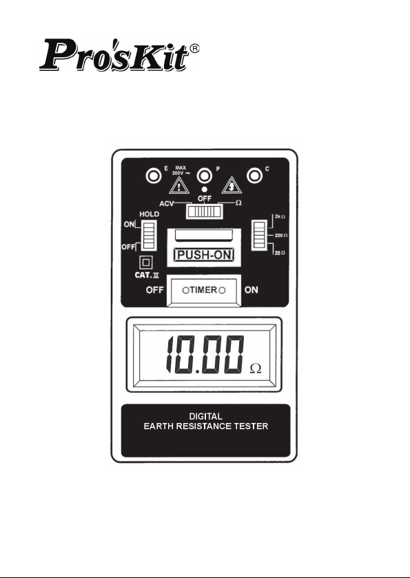
5.LAYOUT
(1) "E", "P", "C" Terminal
(2) Operation Indicator
(3) Data Hold Switch
(4) Timer Off Button
(5) LCD Display
(6) Function Switch
(7) Ohm Range Switch
(8) Pushbutton
Operation
(9)Timer On Button
5
Page 7

6.MEASURING METHODS
BEFORE PROCEEDING MEASUREMENT, READ
SAFETY NOTES ON PAGE 2.
In proceeding with measurement, if "B"
symbol appears on the display, replace
with new batteries.
●Earth Voltage Measurement:
(1) Connection with test leads:
Connect green, yellow test leads to instrument
terminals E, P with auxiliary earth bars P1,
driven into earth " IN A STRAIGHT
LINE".(Fig.1)
(2) Set the function switch to ACV position and
press the"PUSH-ON" button and "TIME ON"
button at the same time make certain that the
voltage reading is LESS THAN 10V AC,
otherwise accurate earth resistance
measurement may not be made.
6
Page 8

●Earth Resistance Measurement:
(1) Connection with test leads:
Connect green, yellow and red test leads to
instrument terminals E, P and C with auxiliary
earth bars P1, C1 driven into earth "IN A
STRAIGHT LINE".(Fig.2)
(2) Set the Range Switch to suitable range and
set the function switch to Ω position then press
the PUSH-ON BUTTON and TIME ON BUTTON
at the same time and take the reading on the
display.
●When none of E, P and C terminals
connected with test leads, the display shows
"1" at Ω function.
●Follow the proper connection such as Fig.2,
the LED(red) indicator will lit. This proves a
correct current circulation
WARNING
is under its operation.
7
Page 9

7.MAINTENANCE
●Battery Replacement:
When the symbol "B" appears on the display,
replace the batteries as follows :
(1) Disconnect the test leads from the instrument
and turn off the power.
(2) Use a screwdriver to unscrew the screw on
back cover then slide the cover, take out the
batteries and replace with new batteries Type
SUM-3.
(3) Place back cover and secure by a screw.
●Cleaning and storage:
(1) Periodically wipe the case with a damp cloth
and detergent ; do not use abrasives or
solvents.
(2) If the meter is not to be used for periods of
longer than 60 days, remove the batteries and
store them separately.
WARNING
To avoid electrical shock or damage to the
meter, do not get water inside the case.
8
 Loading...